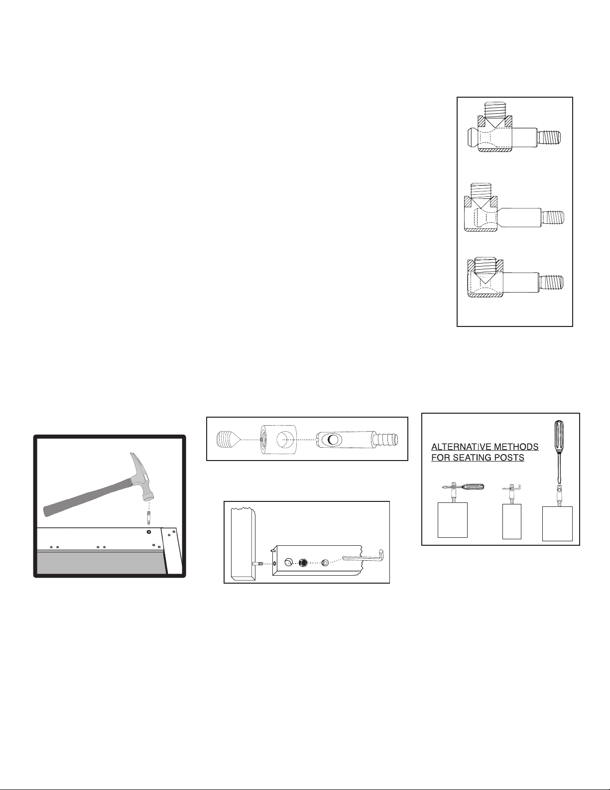
WRONG!
Post needs to be screwed deeper.
WRONG!
Post needs to be backed out.
CORRECT!
Set screw secures post properly.
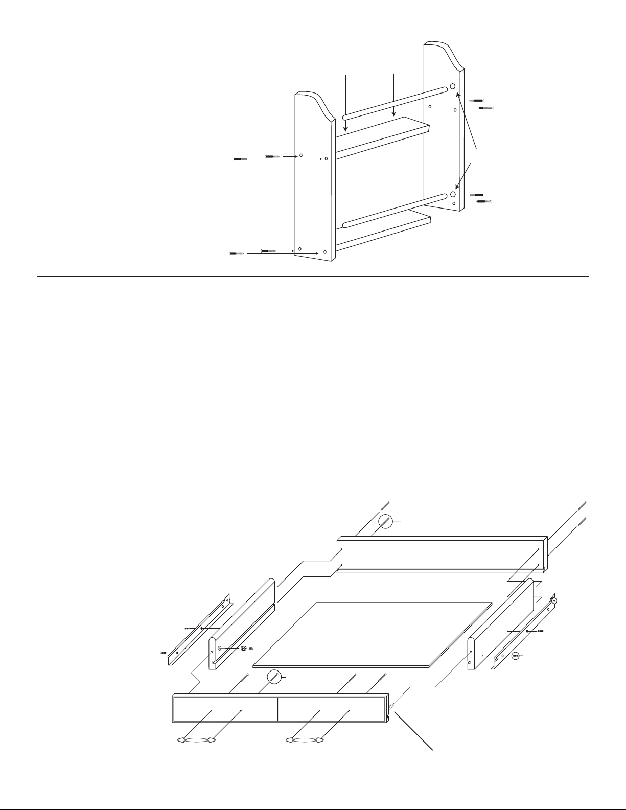
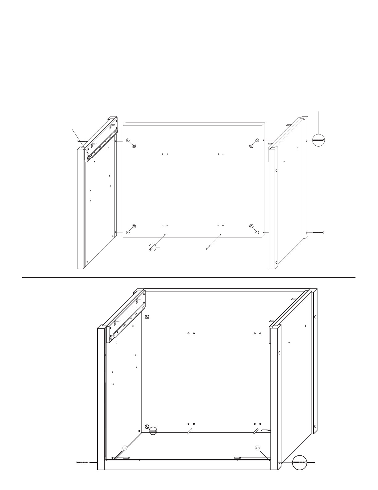
Step 1
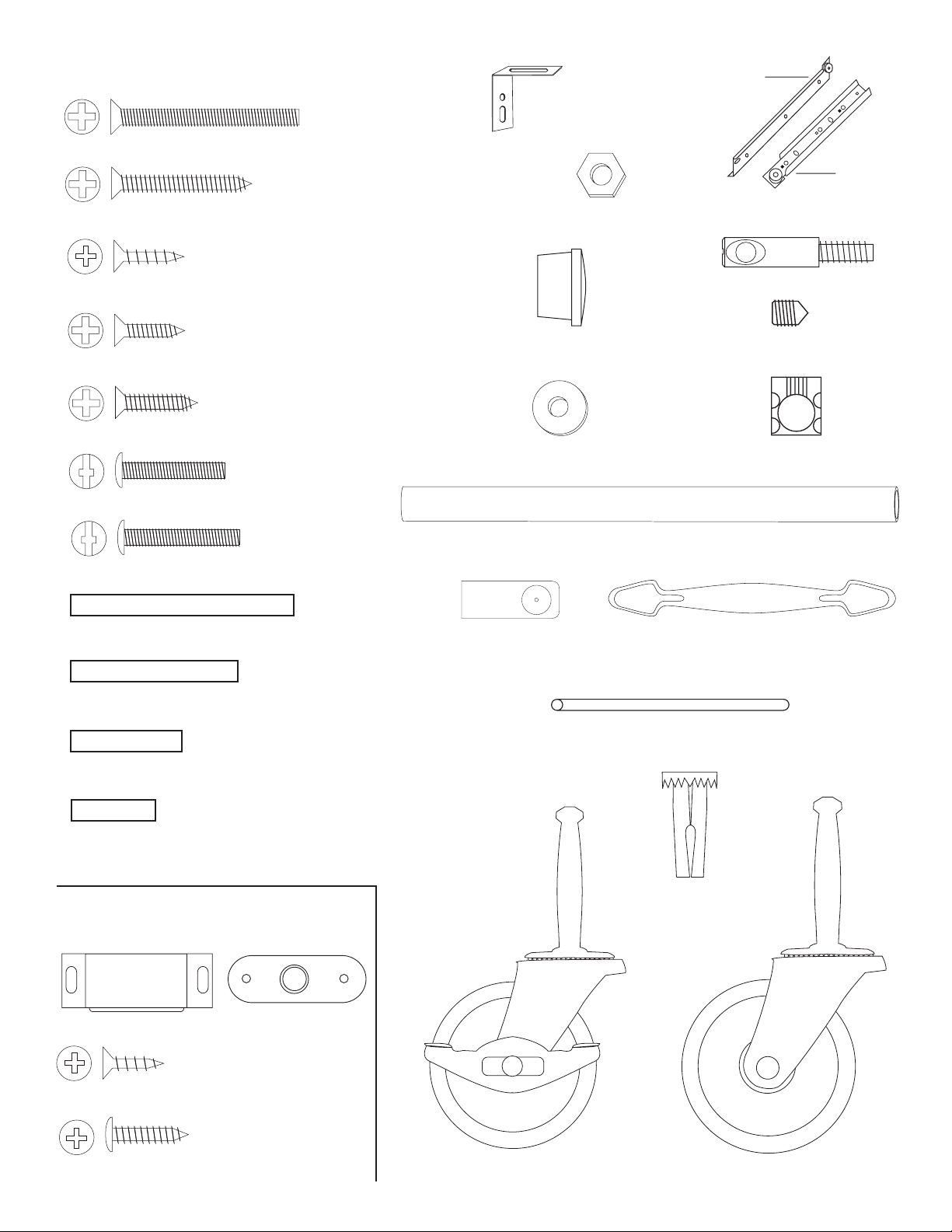
1. The Bastion fastening system consists of a steel post (threaded on one end with a hole
through the shaft on the other end); a Barrel Nut (cylindrical barrel-shaped with threaded
open end & holes through the sides); and a Set Screw (Phillips slot on one end, pointed on
the other)
2. To attach Posts: A) Dip threads of Post in vegetable oil. B) Align threaded end of Post
with hole in wood, tap on slotted end with hard hammer until threads enter, then tighten
down using a flat head screw driver or the provided allen wrench (See the Illus. Bas. 3 for
alternate seating methods). DO NOT TRY TO HAMMER THE POST ALL THE WAY IN AS IT
WILL STRIP THE POST HOLE. C) When solid shaft of Post hits wood, back out
approximately ½ turn until the hole in the posts is properly aligned as per step by step
directions. For example: the holes in the posts on the inside of the drawer front will be
parallel with the long length of the drawer front when properly seated.
3. A) Place a Barrel Nut into the nut access hole, so that the threads in the nut face out.
The small notches on either side of the nut opening, indicate the location of the holes
through the sides of the nut. B) Insert the posts through the end of the braces (or drawer
sides); through the holes in the sides of the nut. When properly aligned, you will see the hole
in the post inside the barrel nut. Post hole should be slightly off-center toward the wood.
4. Insert the Set Screw into the threaded end of the nut and tighten down. The tip of the Set
Screw will seek the center of the hole in the Post as it is tightened down, forcing the Nut
toward the main shaft of the Post. This is what tightens the wooden parts together. Set
screws should thread easily – DON’T CROSS THREAD! If Set Screw doesn’t thread easily,
check position of the hole in Post.
5. If the wooden parts are not tight against each other, the Post needs to be screwed a half
turn at a time until wood joints are tight.
Illustration Bas. 1
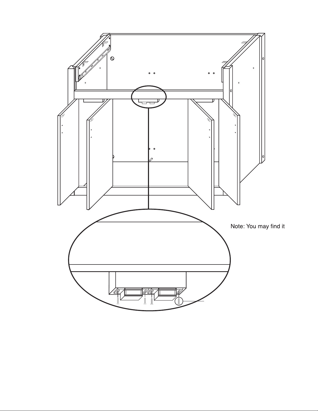
Step 2
Illustration Bas. 2 Illustration Bas. 3
TIPS ON HOW THE BASTION FASTENING SYSTEM WORKS
See video on our website!
If you have any questions regarding assembly or missing or damage
parts, call our customer support number:
607-652-7321 or 888-732-7321.
Customer Support Hours are 8am-5pm Mon. - Fri. Eastern Time zone.
Allen Wrench Provided