CBE A915 User manual

A915
CARICA BATTERIE ELETTRONICO
ELECTRONIC BATTERY CHARGER
ELEKTRONISCHES BATTERIE-LADEGERÄT
CHARGEUR DE BATTERIES ELECTRONIQUE
20/09/04000188.00
istruzioni d'uso
I
INSTRUCTIONS MANUAL
GB
gebrauchsanweisungen
D
INSTRUCTIONS D'EMPLOI
F

2
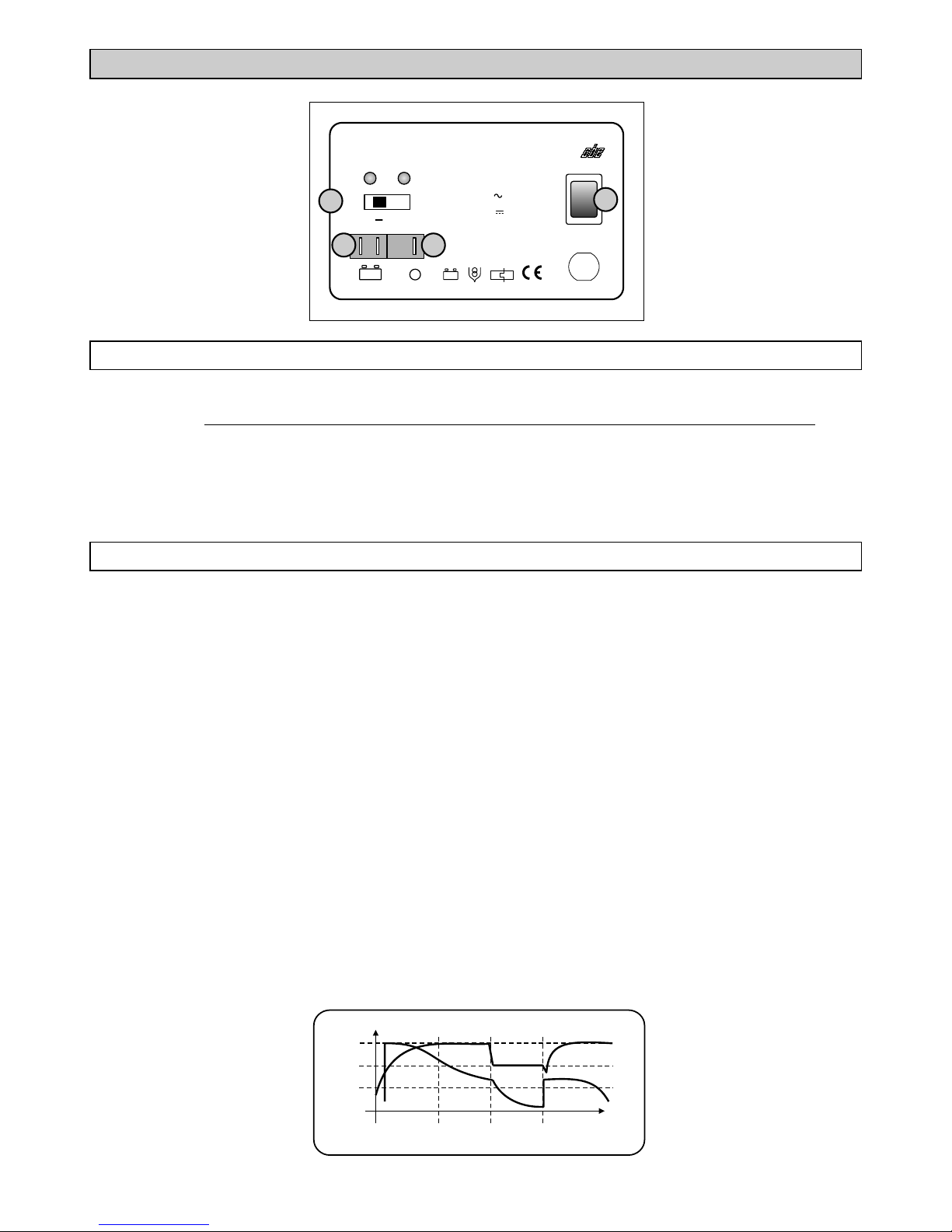
CARICA BATTERIE ELETTRONICO “A 915”
1)
2) Connettore per il collegamento della batteria.
Commutatore per la scelta del tipo di batteria collegata: “Pb” batteria tipo acido, “Gel” batteria di
alimentazione al GEL.
Segnale 12V 50mA di presenza rete 230V.
Interruttore on/off 230V di sicurezza, può rimanere acceso permanentemente.
NB: impostando in modo errato il commutatore si può danneggiare la batteria servizi.
3)
4)
LEGENDA
FUNZIONI
w
w
w
w
E' stato studiato per ricaricare batterie da avviamento (Pb/Acido) o da stazionamento (gel), per uso
continuo e collegate in sistema a tampone.
Collegato in sistema a tampone
Se non è collegata la batteria con una tensione di almeno 3V, il sistema non entra in funzione.
Il sistema di ricarica avviene in tre cicli:
ricarica della batteria con la massima corrente fino al raggiungimento del fine carica di 14,4V (Led
rosso). NB. il fine carica è raggiunto solo se la batteria è efficiente.
quando è raggiunta la soglia di 14,4V, la carica continua per 20 min. (batt. pb) o per 6 ore e 20
min. (batt. Gel).
mantenimento 13,8V costanti (Led verde) In tal modo si garantisce la corrente di mantenimento
per la carica completa. In questa fase il sistema provvede a parzializzare i Tyristor in modo da
rendere quasi nullo il picco di tensione.
Quando la batteria scende sotto il valore di circa 13,6V, dovuto anche all'inserimento di un carico
(utenze), il sistema riparte dalla fase 2.
può essere messo in parallelo con altre fonti di energia (generatore,
carica batterie, pannelli solari, ecc...)
1)
2)
3)
ELEKTRONISCHES BATTERIE-LADEGERÄT
Mod. A 915
230 V
I
0
Vor dem Laden Gebrauchsanweisung lesen! Made in Italy
++
12V S
Stromüberwachung
Ausga n g 12V 13/15 A
Nennleistung 180VA
Eingang 230V 50 Hz
Ortsfest in trockenem Raum einbauen
by
12V
>55 Ah °C
t 40/E
a
13,8V 14,4V
Gel Pb
1
2 3
4
Linea di carica IWUoU
13,3V
V = Volt A = Ampere C = Carico - Load
VA
14,5V
13,8V
V I
C
t
IW Uo U Uo

ITALIANO
Alimentazione
Potenza massima
Corrente di carica:
- nominale
- aritmetica
Controllo corrente
Consumo (rete 230V scollegata)
Controllo automatico fasi di carica
- Carica massima
- Mantenimento
Commutatore scelta batteria (Pb o Gel)
Tempo di carica raggiunta la soglia 14,4V
- Batteria piombo
- Batteria gel
Protezione da sovraccarico
Protezione da sovratemperatura
Protezione da inversione di polarità
Interruttore on/off di sicurezza
Fusibile 12V di protezione
Fusibile 230V di protezione
Segnalazione fasi di carica tramite Led
Collegamento alla rete 230V
Collegamento alla batteria
Collegamento segnale rete
Dimensioni (mm)
Peso (Kg)
di serie
230 Vac 50 Hz / 12Vdc
180 VA
A915
15 A
13 A
0,3 mA
25°C
14,4V
13,8V
Terminale 6,3
Terminale 6,3
tipo auto 20A
interno 3,15A
160 x 200 H105
3,8
20 min.
380 min.
Spina Schuko
Contenitore in alluminio verniciato
Sistema di carica Tampone
CARATTERISTICHE
3
IMPORTANTE: - L'installazione di questo apparecchio deve essere eseguita solamente da
personale tecnico specializzato.
- In caso di un utilizzo improprio dell'apparecchiatura, ne decade la garanzia ed il
produttore declina ogni responsabilità per danni a cose o persone.
- Non eseguire mai manutenzioni con la rete 230V collegata.
CARICA BATTERIE
- Installare il carica batterie in un apposito vano, asciutto ed aerato, fissarlo in modo adeguato.
- Non ostruire le prese d'aria poste sul coperchio ed assicurare un'adeguata ventilazione.
- Prima di scollegare l'apparecchio dalla rete 230V spegnere l'interruttore di sicurezza.
CAVI
- Utilizzare cavi di adeguata sezione, sezione minima 4mm².
- Proteggere i cavi da ogni possibile danneggiamento.
CONSIGLI E VERIFICHE PER L'INSTALLAZIONE

4
ELECTRONIC BATTERY CHARGER “A 915”
1)
2) Connector for the connection of the battery.
Commutator to choose the connected battery: “Pb” lead-acid battery, “Gel” gel-battery.
12V 50mA signal of the 230V net.
on/off safety switch; it can be always on.
3)
4) 230V
If the commutator is set wrongly, you can damage the leisure battery.
LEGENDA
FUNCTIONS
wIt was studied to charge starter (lead-acid) and leisure (gel) batteries connected as a buffer system,
for continuous operation.
If connected in buffer-system it can be paralleled with other energy powers (generator, battery
charger, solar panel, etc...)
The battery charger doesn't work if it is not connected to a battery with a voltage of at least 3V.
The system recharges the batteries in 3 cycles:
Battery recharge at the max. Current, until it reaches the 14,5V value od end-charge.
When the 14,4V value has been reached, the charging goes on for: 20 minutes for lead-acid
batteries, 6 hours and 20 minutes for gel batteries.
Maintenance recharge at 13,8V continuous.
In this way the maintenance current is assured for the full charge. In this cycle the recharging
system chokes the tyristor in order to invalidate the voltage peak.
When the battery voltage is under than 13,6V, the system restarst from the 2nd cycle.
w
w
w
1)
2)
3)
NB: this value is reached only if the battery is well-run.
ELEKTRONISCHES BATTERIE-LADEGERÄT
Mod. A 915
230 V
I
0
Vor dem Laden Gebrauchsanweisung lesen! Made in Italy
++
12V S
Stromüberwachung
Ausga n g 12V 13/15 A
Nennleistung 180VA
Eingang 230V 50 Hz
Ortsfest in trockenem Raum einbauen
by
12V
>55 Ah °C
t 40/E
a
13,8V 14,4V
Gel Pb
1
2 3
4
Charging line IWUoU
13,3V
V = Volt A = Ampere C = Carico - Load
VA
14,5V
13,8V
V I
C
t
IW Uo U Uo

ENGLISH
Mains input voltage
Max. power
Charge current
- nominal
- arithmetic
Current control
Consumption (no connected mains)
Automatic control of charge cycles
- Max charge
- Maintenance
Commutator for battery choice (Pb or Gel)
Length of 14,4V end-charge phase
- Lead type battery
- Standing type battery
Overload protected
Overtemperature protected
Inversion polarity protection
Security on/off switch
12V fuse
230V fuse
Charge signalled by LED
230V connection
Battery connection
Mains signal connection
Dimensions (mm)
Weight (Kg)
Always provided
230 Vac 50 Hz / 12Vdc
180 VA
A915
15 A
13 A
0,3 mA
25°C
14,4V
13,8V
Terminals 6,3
Terminals 6,3
car type 20A
internal 3,15A
160 x 200 H105
3,8
20 min.
380 min.
Schuko plug
Anodized aluminium case
Charge system Buffer battery
SPECIFICATIONS
5
IMPORTANT: - The installation of this device must be carried out by specialized technicians.
- In case of battery charger’s misuse, the guarantee falls off and the manufacturer
declines all responsibility for damages to people and things.
- Do not carry out any maintenance when the battery charger is connected to the
230V power supply net.
BATTERY CHARGER
- Install the battery charger in a dedicated room, dry and ventilated; fix it in a proper way.
- Do not cover air intakes and assure an appropriate ventilation.
- Before disconnecting the battery charger from 230V power supply, turn the security switch off.
CABLES
- Use cables with appropriate section, minimum cross section area 4 mm².
- Protect cables from any possible damage.
ADVICE AND CHECKS

6
ELEKTRONISCHES BATTERIELADEGERÄT “A915”
ZEICHENERKLARUNG
FUNKTIONEN
ELEKTRONISCHES BATTERIE-LADEGERÄT
Mod. A 915
230 V
I
0
Vor dem Laden Gebrauchsanweisung lesen! Made in Italy
++
12V S
Stromüberwachung
Ausga n g 12V 13/15 A
Nennleistung 180VA
Eingang 230V 50 Hz
Ortsfest in trockenem Raum einbauen
by
12V
>55 Ah °C
t 40/E
a
13,8V 14,4V
Gel Pb
1
2 3
4
1)
2)
Kommutator für den Wahl der verbundenen Batterie:
Stecker für den Batterie Anschluss.
“Pb” (Blei/Säure-batterie) oder “Gel” (Blei/Gel-
batterie).
Signal 12V 50mA von 230V-Netz Anwesenheit.
Sicherheitschalter ein/aus 230V. Er kann immer angeschaltet bleiben.
3)
4)
Bei falscher Einstellung des Umschalters kann man die Aufbaubatterie beschädigen.
w
w
w
w
Das Gerät wurde für die Wiederaufladung folgender Batterietypen entwickelt: Fahrzeug oder
Verbraucherbatterien (Gel), bei Dauerbetrieb und im Pufferbetrieb angeschlossen.
Wenn das Gerät in Pufferbetrieb angeschlossen ist, kann er in Parallelbetrieb mit weiteren
Stromquellen (Generator, Ladegeräte, Solarpanele...) angeschlossen werden.
Wenn die angeschlossene Batterie nicht zumindest 3V aufweist, startet das System nicht.
Die Beladung erfolgt in drei Phasen:
Aufladung der Batterie mit dem maximalen Strom bis zur Endladungspannung von 14,4V (rote
Led).
Wann der Wert von 14,4V erreicht wird, wird die Beladung für 20 Min. für Bleibatterien, und für 6
St. und 20 Min. (für Gelbatterien) fortgeführt.
13,8V konstante Erhaltung (grüne Led). Damit wird der Erhaltungsstrom für die vollstandige
Aufladung gesichert. Während dieser Phase werden die Thyristoren geregelt, um Spannungspitzen
zu vermeiden.
Wenn die Batterie unter 13,6V absinkt, auch durch den Einsatz von einem Verbraucher, startet das
System die Phase 2 noch einmal wieder.
1)
2)
3)
Anmerkung: die Endaufladung wird nur bei gut erhaltener Batterie erreicht.
Ladekennlinie IWUoU
13,3V
V = Volt A = Ampere C = Carico - Load
VA
14,5V
13,8V
V I
C
t
IW Uo U Uo

DEUTSCH
7
Standard
TECHNISCHE DATEN
Versorgung
Maximale Kraft
Ladestrom:
- genannter
- aritmetischer
Stromkontrolle
Verbrauch (Netz 230V ausgeschaltet)
Automatische Kontrolle Ladephasen
- Maximale Ladung
- Erhaltung
Kommutator Batteriewahl (Blei oder Gel)
Ladezeit Erreichung 14,4V
- Bleibatterie
- Gelbatterie
Schutz vor Überlastung
Schutz vor Übertemperatur
Schutz vor Verwechslung der Pole
Sicherheitsschalter on/off
Schutzsicherung 12V
Schutzsicherung 230V
Anzeige der Ladephasen mittels Led
Verbindung am Netz 230V
Verbindung an die Batterie
Verbindung Netzsignal
Dimensionen (mm)
Gewicht
230 Vac 50 Hz / 12Vdc
180 VA
A915
15 A
13 A
0,3 mA
25°C
14,4V
13,8V
Kabelschuh 6,3
Kabelschuh 6,3
Wie beim Pkw 20A
Innen 3,15A
160 x 200 H105
3,8 Kg
20 Min.
380 Min.
Schuko Stecker
Aluminiumbehälter pulverbeschichtet
Ladesystem Pufferbetrieb
RATSCHLÄGE UND KONTROLLE ZUM EINBAU
WICHTIG : - Einbau von diesem Gerät darf nur vom einem Fachmann durchgeführt werden.
- Im Falle vom Mißverbrauch man verwirkt die Garantie und haftet der Hersteller
für keine Sach- oder Personenschaden.
- Keine Wartungsarbeiten, wenn 230V Netz anliegt.
LADEGERÄT
- Ladegerät in einem Raum einbauen. Einbau muß angemessen durchgeführt.
- Die Belüftung beim Deckel nicht verstopfen und eine angemessene Belüftung versichern.
- Bevor das Ladegerät vom 230V Netz auszuschließen, den Schalter ausmachen..
KABEL
- Kabel mit angemessenen Querschnitt benutzen, Mindestquerschnitt 4mm².
- Die Kabel gegen alle mögliche Beschädigungen schutzen.
trockenen und belüfteten

8
CHARGEUR DE BATTERIES ELECTRONIQUE “A 915”
LEGENDE
FONCTIONS
1)
2)
Commutateur pour le choix du type batterie branchée: “Pb” batterie type acid, “Gel” batterie
d’alimentation au gel.
Connecteur pour le branchement de la batterie.
3)
4)
Signal 12V 50mA de présence reseau 230V.
Interrupteur on/off 230V de sûreté, il peut être toujours allumé.
Le commutateur posé d'une manière erronée peut endomager la batterie services.
w
w
w
w
Il a été étudié pour recharger les batteries démarrage (Pb/Acid) ou type stationnement (gel), pour
usage continu et raccordées en système à tampon.
Branché en système à tampon il peut être mis en parallel avec des autre source d’energie
(generateur, chargeur, panneau solaires, etc. )
Si la batterie raccordée n'a pas au moins un tension de 3V, le système n'entre pas en fonction.
Le système de recharge se fait en trois cycles:
recharge de la batterie avec le maximum de courant jusqu'à atteindre la fin de charge de 14,4V
(Led rouge).
lorsque le seuil de 14,4V est atteint, la charge continue pour un temps de 20 min. (batt. pb), ou
pour 6 heures et 20 min. (batt. gel) .
maintien 13,8V(Led vert) de façon à garantir le courant de maintien pour la charge complète.
Dans cette phase le système pourvoit aussi à partager les Tyristors de façon à rendre presque nul le
pic de tension.
Quand la batterie descend au-dessous de la valeur d'environ 13,6V , dû au branchement d'une
charge (utilisations), le système repart de la phase 2.
1)
2)
3)
NB: la fin de charge est atteinte uniquement si la batterie est en bon état.
ELEKTRONISCHES BATTERIE-LADEGERÄT
Mod. A 915
230 V
I
0
Vor dem Laden Gebrauchsanweisung lesen! Made in Italy
++
12V S
Stromüberwachung
Ausga n g 12V 13/15 A
Nennleistung 180VA
Eingang 230V 50 Hz
Ortsfest in trockenem Raum einbauen
by
12V
>55 Ah °C
t 40/E
a
13,8V 14,4V
Gel Pb
1
2 3
4
Ligne de charge IWUoU
13,3V
V = Volt A = Ampere C = Carico - Load
VA
14,5V
13,8V
V I
C
t
IW Uo U Uo

FRANÇAIS
di serie
Alimentation
Puissance maximum
Courant de charge :
- nominal
- arithmétique
Contrôl courant
Consommation (reseau 230V débranchée)
Contrôl automatique phase de charge
- Charge maximum
- Maintien
Commutateur choix batterie scelta batteria (Pb o Gel)
Temps de charge atteint la seuil de 14,4V
- Batterie plomb
- Batterie gel
Protection de surcharge
Protection de surtempérateur
Protection inversion polarité
Interrupteur on/off de sûreté
Fusible 12V de protection
Fusible 230V de protection
Signalisation de charge par Led
Branchement à la reseau 230V
Branchement à la batterie
Branchement signau reseau
Encombrement (mm)
Poids
230 Vac 50 Hz / 12Vdc
180 VA
A915
15 A
13 A
0,3 mA
25°C
14,4V
13,8V
faston 6,3
faston 6,3
type auto 20A
intérieur 3,15A
160 x 200 H105
3,8 Kg
20 min.
380 min.
fiche Schuko
Boîtier en alluminium verni
Système de charge Tampon
CARACTERISTIQUES
9
CONSEILS ET VERIFICATIONS POUR L'INSTALLATION
IMPORTANT: - L'installation de cet appareil doit être faite seulement par un technicien
spécialisé.
- En cas d'emploi abusif de l'appareil, la garantie déchue et le fabricant
décline toute responsabilité pour les dégâts caus s à choses ou personnes.
- Ne jamais faire l' entretien avec le réseau 230V branché.
é
CHARGEUR DE BATTERIE
- Installer le chargeur de batterie dans un endroit propre, sec et ventilé, le fixer d'une façon convenable.
- Ne pas obstruer les prises d'air sur le couvercle et assurer une ventilation adéquate.
- Avant de débrancher l'appareil du réseau 230V, presser le bouton de sécurité.
CABLES
- Utiliser des câbles de section adéquate, minimum 4mm .
- Protéger les câbles de tout endommagement.
2

10
NOTE / NOTES / MERKUNGEN / NOTES

11
NOTE / NOTES / MERKUNGEN / NOTES

w
w
w
w
I dati riportati nei fogli di istruzioni possono subire modifiche senza preavviso alcuno, questo è dovuto alle
continue migliorie tecniche. I disegni e i testi riprodotti sono proprietà della CBE. E' vietata la riproduzione
integrale o parziale e la comunicazione a terzi senza l'autorizzazione scritta.
Technical data on instructions sheets can be modified without notice, because technical improvements
are continually made. Design and texts are CBE property. Integral or partial reproductions are no
admitted as well as communications to third parties without written permission.
Die in den Gebrauchsanweisungen geführten Daten können ohne Vorankündigung geändert werden, in
Zusammenhang mit den technischen Verbesserungen. Die veröffentlichten Abbildungen und Texte sind
Eigentum der Fa. CBE. Jegliche Art von Vervielfältigung, komplett oder teilweise, ist ohne schriftliche
Genehmigung untersagt.
Les données reportées dans les pages des instructions peuvent subir des modifications sans aucun
préavis, ceci en vue des continuelles améliorations techniques. Les dessins et les textes reproduits sont
de propriété de la CBE. La reproduction totale ou partielle et la communication à tiers, sans autorisation
écrite sont interdites.
89/336 EMC
73/23 e 93/68 EEC
Spini di Gardolo, 116 - 38014 Gardolo (TN) - Italy
CBE Elettrotecnica
Table of contents
Languages:
Other CBE Batteries Charger manuals