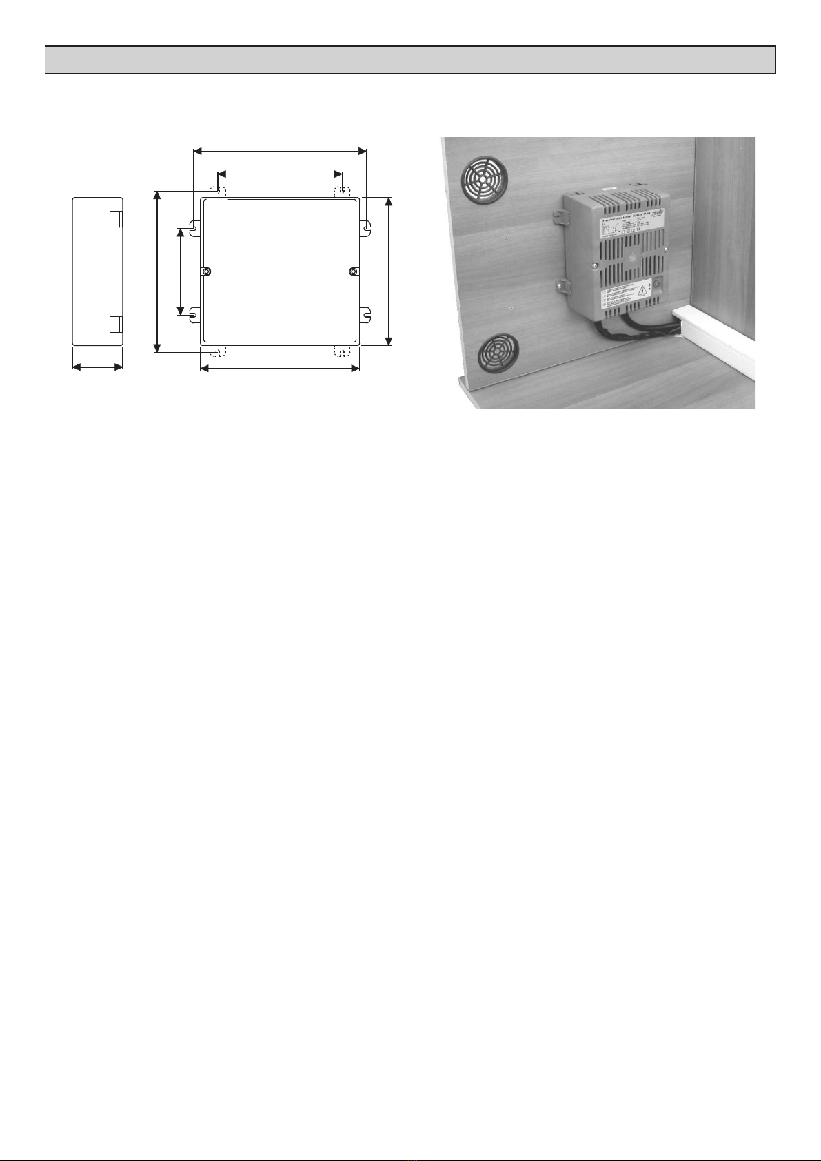
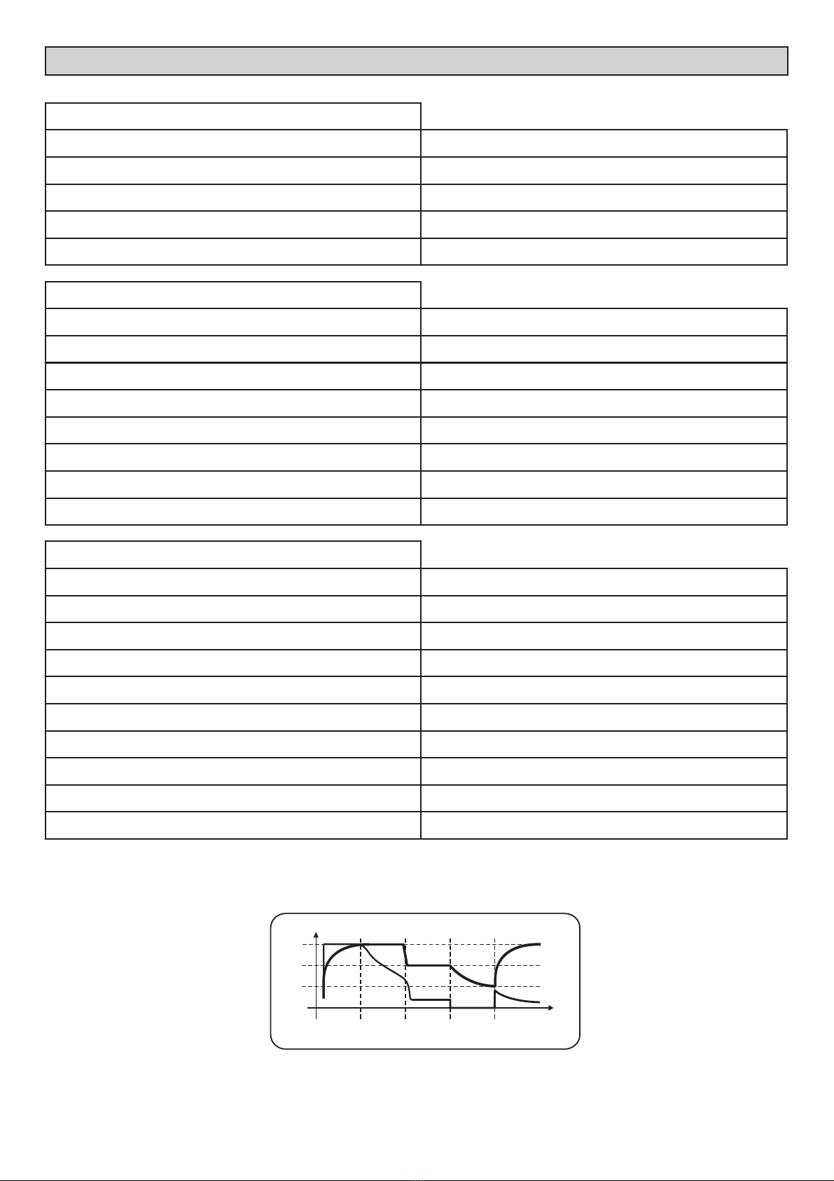
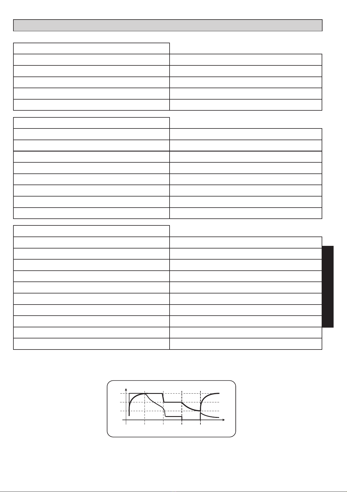
Abbildung 1 - DIMENSIONEN (mm):
EINBAU
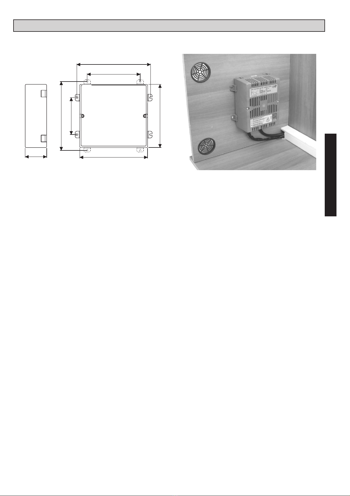
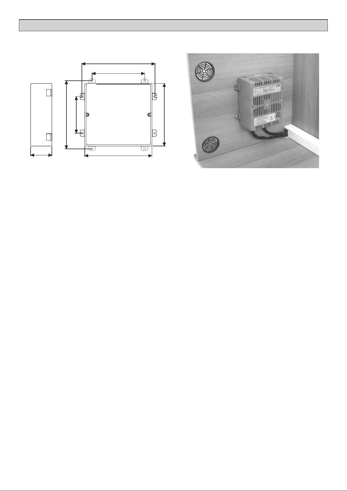
Abbildung 2 - VERTIKALER EINBAU
WICHTIG : - Einbau von diesem Gerät darf nur vom einem Fachmann durchgeführt werden.
- Im Falle vom Mißverbrauch man verwirkt die Garantie und haftet der Hersteller
für keine Sach- oder Personenschaden.
- Achtung, das Batterieladegerät nicht anschließen:
während der Verwendung eines Generatorsatzes mit nicht stabilisierter
Ausgangsspannung
mit Netzspannung über dem Nennwert (230Va.c. ±10%)
- Keine Wartungsarbeiten, wenn 230Va.c. Netz anliegt.
1
1
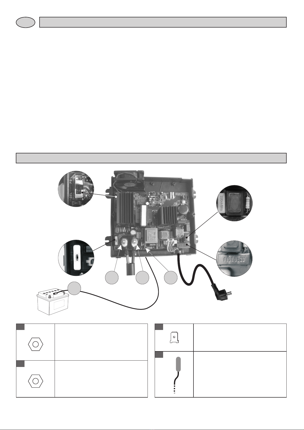
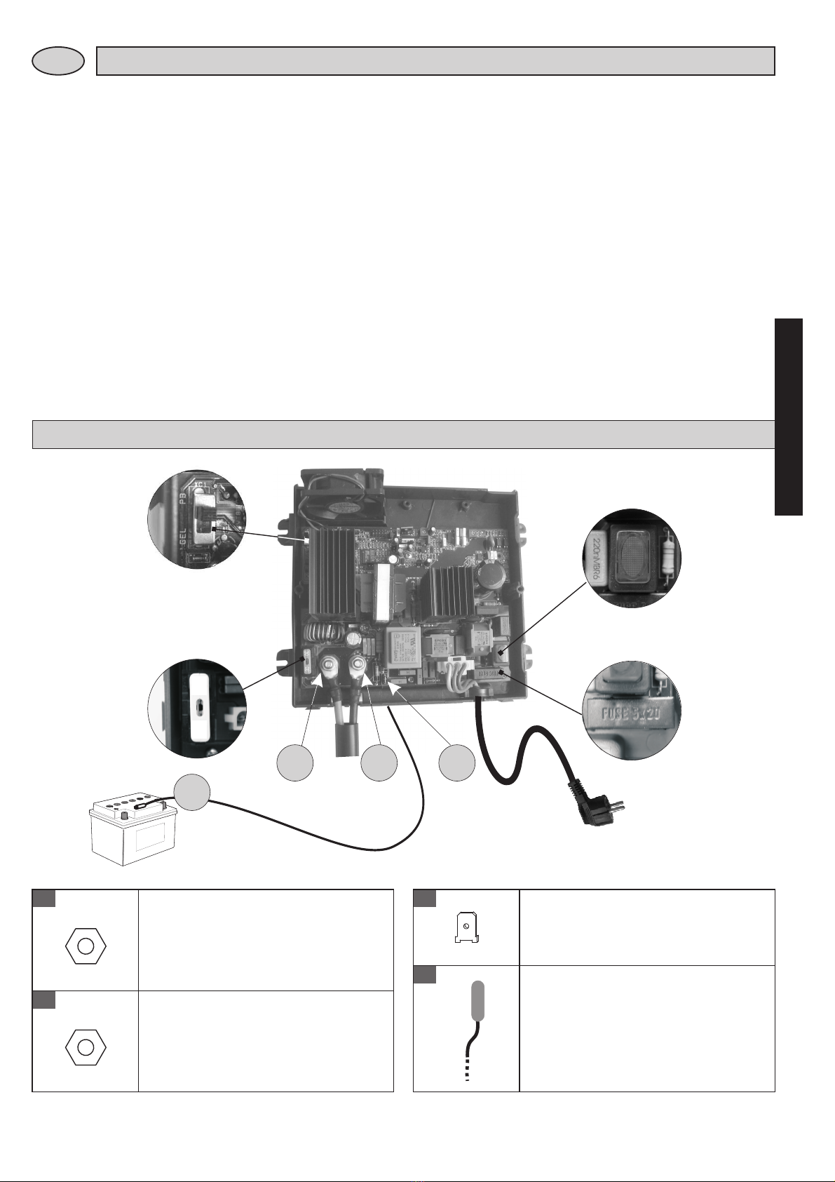
LADEGERÄT
KABEL
- Kabel mit angemessenen Querschnitt benutzen, Mindestquerschnitt 6mm².
- Die Kabel gegen alle mögliche Beschädigungen schutzen.
BATTERIE
- Ladegerät in einem eigens vorgesehenen, trockenen und belüfteten Fach einbauen. Die beste
Leistungsfähigkeit erhält man, wenn es vertikal eingebaut (siehe Abbildung 2) wird und ein
Mindestabstand von 300 mm vom Vorderteil und 100 mm vom oberen und unteren Teil des Ladegeräts
zu den das Fach umgebenden Teilen garantiert wird.
- Nicht die Belüftungen auf dem Deckel verstopfen.
- Um einen entsprechenden Luftaustausch im Fach zu garantieren, empfehlen wir die Installation von
zwei Belüftungsöffnungen (eine oben und eine unten, siehe Abbildung 2), die eine Betriebstemperatur
innerhalb des Fachs von nicht über 50 °C gewährleisten.
- Darauf achten, dass der 230Va.c.-Sicherheitsschalter zugänglich ist.
- Die Verbindung mit dem Versorgungsnetz muss unter Einhaltung der nationalen Installationsregeln
ausgeführt werden.
- Bevor das Ladegerät vom 230Va.c.-Netz abgeklemmt wird, den Sicherheitsschalter abschalten.
- Die Installation erfolgt mittels der 4 Befestigungsfüße, die leicht an den 4 Seiten positionierbar sind.
- Das Ladegerät kann installiert werden, indem es, unter Verwendung der entsprechenden
Einsteckmodule, mit den Verteilungstafeln CBE 12V und 230V kombiniert wird.
- Die Pb-Säure-Batterie muss an einem gut gelüfteten Ort positioniert werden.
- Nur aufladbare 12Vd.c.-Bleibatterien verwenden (mit Kapazität >40Ah).
- "Nicht aufladbare" Batterien nicht wieder aufladen.
- Die leeren Batterien müssen unter Einhaltung der geltenden Umweltschutznormen entsorgt werden.
Achtung:
10
180
190
85
160
110
197
207