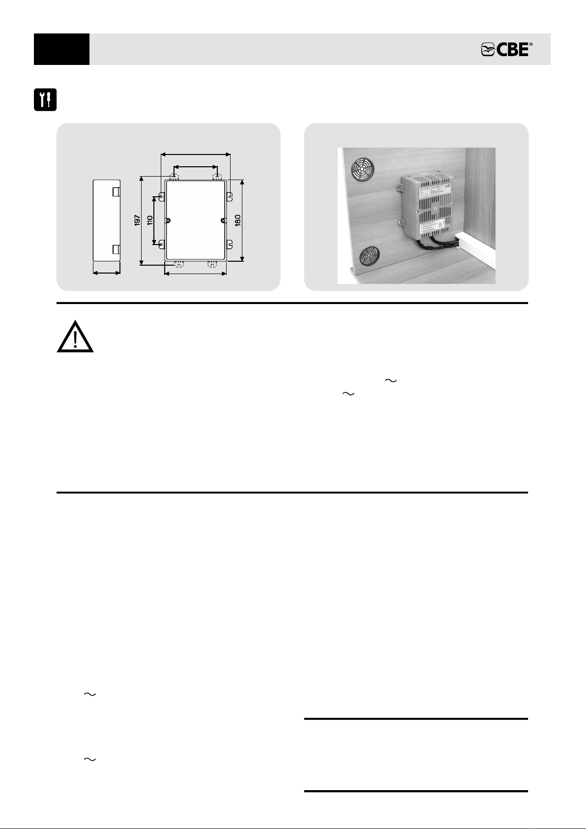
CBE CB510-3 User manual

CB510-3
ELECTRONICS FOR CARAVANNING
ed. 08/2021 cod. 000229 Rev.00
ENERGY LINE
EN
ISTRUZIONI D’USO
USER’S MANUAL
INSTRUCTIONS D’EMPLOI
BEDIENUNGSANLEITUNG
IT
DE
FR


CARICA BATTERIE SWITCHING
INFORMAZIONI GENERALI
Il carica batterie switching CB510-3, specifico per il
settore camper e nautico, è in grado di caricare
batterie al piombo a 12V in modo automatico, con
differenti valori di carica in funzione della posizione
impostata tramite il selettore posizionato all’interno.
La tecnologia switching ad alta frequenza permette di
ottenere elevati rendimenti con pesi e dimensioni
ridotte.
Il carica batterie è protetto da sovratemperatura e le
uscite a 12V sono protette da corto circuito e da
inversione di polarità.
Sistema di ricarica automatico a 6 fasi
NB: Il fine carica è raggiunto solo se la
batteria è efficiente.
Fase 3: Absorption - Completamento della carica
della batteria con tensione di fine carica
costante per il tempo definito dalla linea di
carica con progressiva riduzione della
corrente.
Fase 2: Bulk - carica della batteria con la massima
corrente fino al raggiungimento della
tensione di fine carica.
Fase 1: Desulphation - all’accensione del carica
batterie, solo se la batteria lo necessita,
questa viene caricata ad una tensione di
15,2V fino a quando la corrente supera i
2A o comunque per un massimo di 2 ore.
Fase 4: Float - Carica di mantenimento a tensione
costante per un tempo massimo di 15 ore.
Un elevato assorbimento dalla batteria
comporta la ripartenza dalla fase .Bulk
- Il carica batterie non fornisce più
energia e passa alla fase di solo
quando la tensione della batteria scende
sotto i 13V .
Fase 5: Stand-by
Refresh
- La batteria viene caricata alla
tensione di carica per un tempo
massimo di 1h; questa fase è pensata per
compensare l’autoscarica della batteria
durante eventuali prolungati periodi di
inattività. Successivamente la carica riparte
dalla fase di .
Fase 6: Refresh
Bulk
Float
Nella maggior parte dei casi il selettore può essere
impostato in posizione «A» per batterie al piombo-
liquido, in posizione «B» per batterie al piombo-gel e
in posizione «C» per batterie AGM.
Si consiglia comunque di consultare la scheda
tecnica della batteria collegata.
La posizione del selettore deve essere impostata
in funzione delle tensioni di carica più adatte al
tipo di batteria installata.
DESULPHATION BULK ABSORPTION FLOAT STAND-BY REFRESH
Selettore in posizione “A”
Soglia limite
15,2V
15,2V
15,2V
Max 2h
Max 14,1V
Max 14,4V
Max 14,7V
1,5h
8h
3h
13,5V
13,8V
13,8V
Max 15h
0A
0A
0A
V< 13,0V
14,1V
14,4V
14,7V
Max 1h
Selettore in posizione “B”
Selettore in posizione “C”
1 2 3 4 5 6
3
IT

4
IT
COLLEGAMENTI
I dati tecnici sono riportati anche sull’etichetta interna al coperchio
230V On/Off
Fuse 230V
F2 - T A
3.15
Sensore temperatura
mod."CTCB" (optional) da
posizionare in prossimità della batteria
L=3mt
Selettore di
linea di carica
Connettore
collegamento sensore
temperatura “CTCB”
3
B
C
A
COLLEGAMENTO 12V
2) Alimentazione - 12V
3) /
1) Alimentazione + 12V
4 «S») Segnale rete (+12V )
COLLEGAMENTO 230V
1) Terra
3) Fase
2) Neutro
1)
2)
3)
S-
+
N L
Sensore di temperatura da della batteria e dove
non possa essere influenzato da altre fonti di calore.
(mod."CTCB") posizionare in prossimità
Se collegato, modifica i valori di tensione di carica in funzione della temperatura rilevata.
COLLEGAMENTO (optional)SENSORE TEMPERATURA BATTERIA
Fuse 2V
A
1
F1 - 15
1 2

IT
CARATTERISTICHE TECNICHE
DATI TECNICI DI INGRESSO
Tensione nominale
Potenza massima
Fusibile di protezione rif. F2
Interruttore di sicurezza
50÷60 Hz
230V 10% ±
T 3.15A (vetro 5x20)
230V luminoso
Frequenza
150 W
DATI TECNICI DI USCITA
Tensione di Bulk
Corrente massima
Linea di carica
Protezione corto circuito e
inversione di polarità rif. F1
Protezione termica
Segnale presenza rete (S)
Tensione di Float
IUoU
Sì
12V ; 50 mA
14, V ( ) - 14, V ( )1 A 4 B - 14,7V (C)
13, V ( ) - 13, V ( )5 A 8 B - 13,8V (C)
3 posizioni (A - B - C)
Selettore di linea di carica
1 A0
15A (lama)
DATI TECNICI GENERALI
Collegamento alla rete
Collegamento alla batteria
Temperatura ambiente
Direttiva bassa tensione
Direttiva compatibilità elettromagnetica
86 %
Connettore tipo "mate-n-lock" 3 poli
Connettore tipo "mate-n-lock" 4 poli
180 x 140 x 85 (mm)
1kg
0 - +50 °C
Ventilazione
Rendimento
Dimensioni
Peso
No
2014/35/UE
2014/30/UE
5
Sensore temperatura optional

6
IT
INSTALLAZIONE
140
85
110
157
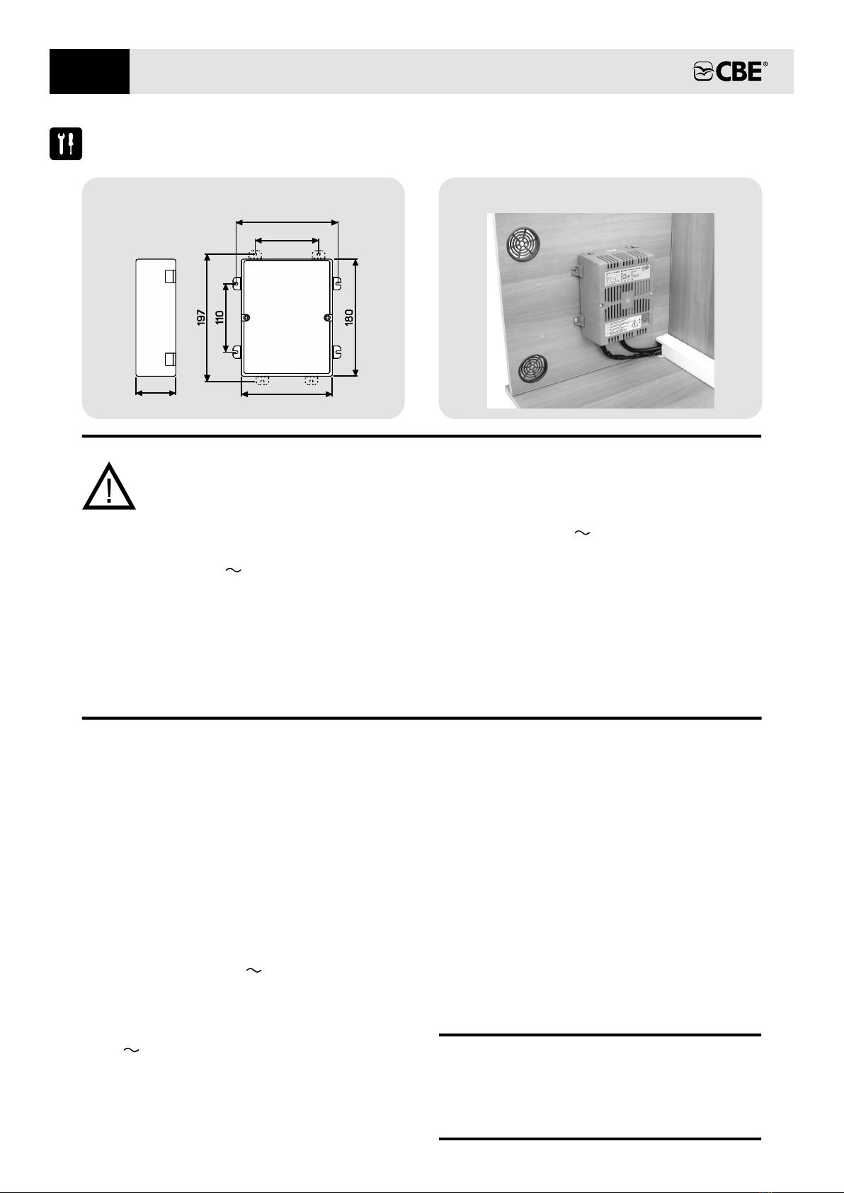
Fig.1 - DIMENSIONI (mm):
Fig.2 - INSTALLAZIONE VERTICALE
IMPORTANTE:
> L'installazione di questo apparecchio deve essere eseguita solamente da personale
tecnico specializzato.
> Attenzione, non collegare il carica batterie:
- durante l'utilizzo di un gruppo elettrogeno con tensione d'uscita non stabilizzata
- con tensione di rete superiore al valore nominale (230V ±10%)
> Non eseguire mai manutenzioni con la rete 230V collegata.
> In caso di un utilizzo improprio dell'apparecchiatura, ne decade la garanzia ed il
produttore declina ogni responsabilità per danni a cose o persone.
> L’apparecchio può essere utilizzato da bambini di età non inferiore a 8 anni e da persone
con ridotte capacità fisiche, sensoriali o mentali, o prive di esperienza o della necessaria
conoscenza, purché sotto sorveglianza oppure dopo che le stesse abbiano ricevuto
istruzioni relative all’uso sicuro dell’apparecchio e alla comprensione dei pericoli ad esso
inerenti. I bambini non devono giocare con l’apparecchio.
- Per garantire un'adeguato ricambio d'aria nel vano
consigliamo l'installazione di due bocche di
areazione (una posta in alto ed una in basso, vedi
figura 2) che assicurano una temperatura di lavoro
interna al vano non superiore ai 50 °C.
- Il collegamento alla rete di alimentazione deve essere
eseguito rispettando le regole di installazione
nazionali.
- Prima di scollegare l'apparecchio dalla rete
230V spegnere l'interruttore di sicurezza.
- Installare il carica batterie in un apposito vano,
asciutto ed aerato; il miglior rendimento si ottiene con
un'installazione verticale (vedi figura 2), garantendo
una distanza minima di 300mm dalla parte frontale e
di 100mm dalla parte inferiore e superiore del carica
batterie alle parti circostanti il vano.
- Non ostruire le prese d'aria poste sul coperchio.
- Fare attenzione affinché l'interruttore di sicurezza a
230V sia accessibile.
- L'installazione avviene tramite n° 4 piedini di
fissaggio, facilmente posizionabili sui 4 lati.
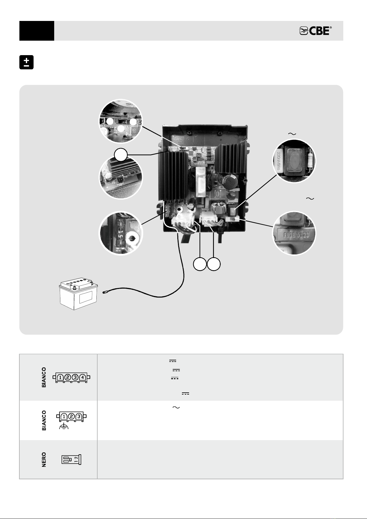
CARICA BATTERIE
- Collegamento alla batteria: utilizzare cavi tipo N07 V-K
di adeguata sezione (sezione minima 4mm²).
- Collegamento alla rete: utilizzare cavo 3x1.5mm²,
tipo H05 RN-F o cavi equivalenti .
- La batteria al Pb-Acido deve essere posizionata in
un luogo ben ventilato.
- Fissare i cavi con gli apposati "bloccacavi" in
dotazione.
- Il carica batterie può essere installato abbinandolo ai
quadri distribuzione CBE 12V e 230V utilizzando gli
appositi incastri modulari.
- Usare solo batterie 12V (6 celle) al piombo
ricaricabili (con capacità >40Ah).
CAVI
BATTERIE
- Proteggere i cavi da ogni possibile danneggiamento.
> Le batterie esaurite devono essere smaltite
attendendosi alle norme vigenti sulla tutela
dell'ambiente.
ATTENZIONE:
> Non ricaricare batterie "non ricaricabili".

SWITCH-MODE BATTERY CHARGER
GENERAL INFORMATION
The CB51 switch-mode battery charger has
been expressly designed for the caravanning and
boating sector and can automatically charge 12V
0-3
lead batteries, with different charging values
according to the position set using the selector
positioned inside.
T he battery charger is protected against
overtemperature and the 12V outputs are
protected against short circuit and polarity inversion.
The high frequency switching technology allows
high performances with small dimensions and
limited weight.
6 phase automatic charging system
Phase 1: Desulphation - switching on the
battery charger, only if need ,
is charged at 15.2V until the current
exceeds 2A or for a maximum of 2 hours.
when
ed the battery
Phase 2: Bulk - battery charging with maximum
current until the end- charge voltage is
reached.
of-
Phase 3: Absorption -
end- charge voltage for the time defined
by the charging line with a progressive
current reduction
battery charging at costant
of-
,
until the charging is
completed.
Note: the end- charge voltage is
reached only if the battery is efficient.
of- Phase 6: Refresh Bulk- The battery is charged
voltage for a maximum time of 1h; this
phase designed to compensate for
at the
is the
battery self-discharge. Once completed,
the starts again from the
phase.
charging Float
Phase 4: Float - Maintenance charg at constant
voltage for a maximum time of 15 hours.
ing
A
h load sigh lead to phase starting
again.
Bulk
Phase 5: Stand-by - The battery charger stops
supplying power. It will switch over to the
Refresh phase only when the battery
voltage goes under 13 .
V
The position of the selector must be set according
to the ingmost suitable charg voltages for the
type of battery installed.
for led- batteries, position B for le d-gel acid on « » a
sheet of the battery installed.
I on « »n most cases, the selector can be set position A
batteries and position C for AGM batteries.on « »
Nevertheless, it is recommended to consult the data
DESULPHATION BULK ABSORPTION FLOAT STAND-BY REFRESH
Selector on position “A”
Threshold
15,2V
15,2V
15,2V
Max 2h
Max 14,1V
Max 14,4V
Max 14,7V
1,5h
8h
3h
13,5V
13,8V
13,8V
Max 15h
0A
0A
0A
V< 13,0V
14,1V
14,4V
14,7V
Max 1h
Selector on position “B”
Selector on position “C”
7
EN
1 2 3 4 5 6

B
C
A
CONNECTIONS
Technical data are indicated also the label inside the coveron
230V On/Off
Fuse 230V
F2 - T A
3.15
Temperature sensor
mod."CTCB" (optional)
to be placed close to the battery
Charg line
selector
ing
Connection battery
temperature sensor
“CTCB”
12V CONNECTION
2) - 12V supply
4) Net signal (+12V ) «S»
1) + 12V supply
3 /)
230V
CONNECTION
3) Line
2) Neutral
1) Earth
1)
2)
3)
S-
+
N L
When is adapted according to the temperature
measured by the sensor.
connected, the charging voltage
Temperature sensor (mod. “C , where it cannot
be affected by other heat sources
TCB”) to be placed close to the battery
.
CONNECTION BATTERY TEMPERATURE SENSOR (optional)
8
EN
Fuse 2V
A
1
F1 - 15
3
1 2
L=3mt

SPECIFICATIONS
INPUT TECHNICAL DATA
Nominal voltage
Maximum power
Protection fuse ref. F2
Safety switch
50÷60 Hz
230V 10% ±
T 3.15 glassA ( 5x20)
230V Lumino us
Frequency
150 W
OUTPUT TECHNICAL DATA
Bulk voltage
Maximum output current
Charg lineing
Short circuit and polarity
ioninversion protect ref. F1
Thermal protection
Signal AC power supply (S)
Float voltage
IUoU
Yes
12V ; 50 mA
14, V ( ) - 14, V ( )1 A 4 B - 14,7V (C)
13, V ( ) - 13, V ( )5 A 8 B - 13,8V (C)
3 (A - B - C)positions
Charg line selectoring
10A
15A (car type)
GENERAL TECHNICAL DATA
Mains connection
Battery connection
Room temperature
Low oltage irectivev d
EMC directive
86 %
3-way connector“mate-n-lock"
4-way connector“mate-n-lock"
180 x 140 x 85 (mm)
1kg
0 - +50 °C
Ventilation
Efficiency
Dimensions
Weight
No
2014/35/UE
2014/30/UE
9
EN
Temperature sensor optional

INSTALLATION
140
85
110
157
Fig.1 - DIMENSIONS (mm): Fig.2 - VERTICAL INSTALLATION
> The installation of this device must be carried out by specialist technicians.
> Do not carry out any maintenance when the battery charger is connected to the
230V power supply net.
> In case of battery charger misuse, the guarantee becomes invalid and the manufacturer
declines all responsibility for damages to people and property.
> This appliance can be used by children aged 8 years and with reduced
physical, sensory or mental capabilities or lack of experience knowledge
or more people
or , only
provided they are being supervised or they have been i ed the nstruct concerning use of
the appliance in a safe way and understand the hazards involved. Children shall
not play with the appliance.
that they
> Caution, do not connect the battery charger:
- with power mains voltage exceeding the rated value (230V ±10%)
- when a generator set with non stabilised output voltage is employed
IMPORTANT:
- T he battery charger can be installed together with
CBE 12V and 230V distribution panels, using the
appropriate modular joints.
- M ake sure that the 230V safety switch can be
easily reached.
- T o guarantee proper air exchange, installation of
two air intakes (one placed on the top and one on
the ottom, see figure 2) ensure a working
temperature inside the housing not exceeding
50°C.
b
- T he connection to power supply mains shall be
made in accordance with national installation rules.
- Install the battery charger in an appropriate housing,
dry and ventilated; maximum efficiency can be
obtained hen the battery charger is installed in a
vertical position (see figure 2), keeping the front at a
minimum istance of 300 mm and the bottom and top
at a minimum distance of 100 mm from the housing
sides.
w
d
- I nstallation requires the fixing of 4 pins that can be
easily placed on the 4 sides.
BATTERY CHARGER
- B efore disconnecting the battery charger from
230V power supply, turn the safety switch off.
- Do not cover air intakes.
- B attery connection: use N07 V-K cables having
adequate section (minimum section
4mm²).
cross cross
- F cable fasteningsix the cables with the relevant
devices supplied.
- M ains connection: use a 3x1.5mm² cable, type
H05 RN-F or equivalent.
- Lead-acid batteries shall be positioned in a well
ventilated place.
- Protect cables from any possible damage.
- U (6 cells)se only 12V rechargeable lead batteries
(capacity >40Ah).
BATTERY
CABLES
accordance with existing environmental
protection regulations.
> Exhausted batteries shall be disposed in
WARNING:
> Do not use “not rechargeable" batteries.with
10
EN

CHARGEUR DE BATTERIE À DÉCOUPAGE
INFORMATIONS GENERALES
Le chargeur de batterie à découpage CB51 ,
spécifiquement conçu pour les camping-cars et le
secteur nautique, est en mesure de charger
automatiquement des batteries au plomb à 12V ,
avec différentes valeurs de charge en fonction de la
position définie par le biais du sélecteur positionné à
l’intérieur.
0-3
L contre lese chargeur de batterie est protégé
surchauffes et les sorties à 12V sont protégées
contre les courts-circuits et l’inversion de polarité.
La technologie à découpage à haute fréquence
permet d’obtenir des élevés avec des
poids et des dimensions réduites.
performances
Système de recharge automatique à 6
phases
Phase 1: Desulphation - Lors de l’allumage du
chargeur de batterie, uniquement si la
batterie le nécessite, cette dernière est
chargée à une tension de 15,2V usqu’à
ce que le courant dépasse les 2 A ou bien
pendant au maximum 2 heures.
j
Phase Bulk 2: - Recharge de la batterie avec le
courant maximal jusqu'à ce qu'elle atteigne
la tension de fin de charge.
Phase 3: Absorption - Fin du chargement de la
batterie avec une tension de fin de charge
constante pour la durée définie par les
lignes de charge avec une réduction
progressive du courant.
NB: La fin de charge est uniquement
obtenue si la batterie est performante.
consommationUne élevée de la batterie
entraîne le redémarrage à partir de la
phase de Bulk.
- Le chargeur de batterie ne
fournit plus d’énergie et passe
Phase 5: Stand-by
à la phase
de Refresh uniquement lorsque la
tension de la batterie descend sous les 13
V .
Phase 4: Float - Chargement de maintien à une
tension constante pour une durée
maximale de 15 heures.
- La batterie est chargée à la
tension de charge pour une durée
maximale d’1h; cette phase a été conçue
afin de compenser l’auto-décharge de la
batterie au cours d’éventuelles périodes
prolongées d’inactivité. Ensuite, le
chargement repart en phase de
Phase 6: Refresh
Bulk
Float.
Dans la plus grande partie des cas, le sélecteur
adaptées au type de batterie installée.
fonction des tensions de charge les plus
batteries au gel et en position «C» pour les
au plomb , en position «B» pour les -acide
Il est néanmoins conseillé de consulter la fiche
batteries AGM.
technique de la batterie installée.
La position du sélecteur doit être définie en
peut être mis en position «A» pour les batteries
DESULPHATION BULK ABSORPTION FLOAT STAND-BY REFRESH
Sélecteur en position “A”
Seuil
15,2V
15,2V
15,2V
Max 2h
Max 14,1V
Max 14,4V
Max 14,7V
1,5h
8h
3h
13,5V
13,8V
13,8V
Max 15h
0A
0A
0A
V< 13,0V
14,1V
14,4V
14,7V
Max 1h
Sélecteur en position “B”
Sélecteur en position “C”
11
FR
1 2 3 4 5 6

B
C
A
BRANCHEMENTS
BRANCHEMENT 12V
2) Alimentation - 12V
3) /
1) + 12VAlimentation
4 «S») Signal réseau (+12V )
BRANCHEMENT 230V
2) Neutre
1) Terre
3) Phase
1)
2)
3)
S-
+
N L
Capteur de température (mod."CTCB") et à un endroit
où il ne risque pas d'être influencé par d'autres sources de chaleur.
à fixer à proximité de la batterie
Si celui-ci est raccordé, il modifie les valeurs de tension de charge en fonction de la
température relevée.
BRANCHEMENT CAPTEUR DE TEMPÉRATURE DE LA BATTERIE (en option)
Les données techniques sont également reportées sur l'étiquette interne du couvercle
230V On/Off
Fuse 230V
F2 - T A
3.15
Capteur de température
de la batterie mod. en option"CTCB" ( )
à fixer à proximité de la batterie
L=3mt
Sélecteur de la
ligne de charge
Branchement capteur
“CTCB”
de température de
la batterie
FR
12
Fuse 2V
A
1
F1 - 15
3
1 2

CARACTÉRISTIQUES
DONNÉES TECHNIQUES D'ENTRÉE
Tension nominale
Puissance maximale
Fusible de protection réf. F2
Interrupteur de sécurité
50÷60 Hz
230V 10% ±
T 3.15A ( 5x20)verre
230V ( )lumineux
Fréquence
150 W
DONNÉES TECHNIQUES DE SORTIE
Tension de Bulk
Courant maximal
Ligne de charge
Protection contre les courts-circuits
et l'inversion de polarité réf. F1
Protection thermique
Signal présence de réseau (S)
Tension de Float
IUoU
Oui
12V ; 50 mA
14, V ( ) - 14, V ( )1 A 4 B - 14,7V (C)
13, V ( ) - 13, V ( )5 A 8 B - 13,8V (C)
3 positions (A - B - C)
Sélecteur de la ligne de charge
1 A0
15A lam )( e
DONNÉES TECHNIQUES GÉNÉRALES
Branchement réseauau
Branchement à la batterie
Température ambiante
Directive basse tension
Directive CEM
86 %
Connecteur de type “mate-n-lock” 3 pôles
Connecteur de type “mate-n-lock” 4 pôles
180 x 140 x 85 (mm)
1kg
0 - +50 °C
Ventilation
Rendement
Dimensions
Poids
Non
2014/35/UE
2014/30/UE
FR
13
Capteur de température optional

INSTALLATION
140
85
110
157
Fig.1 - ENCOMBREMENT (mm): Fig.2 - INSTALLATION VERTICAL
- pendant l'utilisation d'un groupe électrogène dont la tension de sortie n'a pas été
- si la tension de réseau est supérieure à la valeur nominale (230V ±10%)
> Ne jamais exécuter d'entretiens avec le réseau 230V ca raccordé.
> L'appareil peut être utilisé par des enfants si ces derniers sont âgés de 8 ans et plus et par
des personnes ayant des capacités physiques, sensorielles, mentales réduites ou encore
par des personnes dépourvues de la moindre expérience ou des connaissances
nécessaires sous réserve que ces derniers soient assistés ou qu'ils aient reçu toutes les
instructions pour une utilisation en toute sécurité de l'appareil et qu'ils aient pris
connaissance des risques inhérents audit appareil. Les enfants ne doivent pas jouer avec
l'appareil.
stabilisée
IMPORTANT:
> L'installation de cet appareil doit être uniquement réalisée par un technicien spécialisé.
> Attention, ne pas brancher le chargeur de batterie:
> Toute utilisation abusive de l'appareil entraînera la déchéance de la garantie et le
fabricant décline toute responsabilité quant aux dégâts causés à des choses ou à des
personnes
.
- Avant de débrancher l'appareil du réseau 230V
ca, éteindre l'interrupteur de sécurité.
- L'installation est exécutée par le biais de 4 pieds
de fixation, facilement positionnables sur 4 côtés.
- Le raccordement au réseau d'alimentation doit
être effectué en respectant les règles nationales en
matière 'installation.d
- Installer le chargeur de batterie dans un lieu
approprié, sec et ventilé ; le meilleur
rendements'obtient avec ne installation verticale
(voir l'image 2), en garantissant une distance
minimum de 300 mm à partir de la artie frontale et
de 100 mm à partir de la partie inférieure et
supérieure du chargeur de batterie aux environs
u
p
du lieu en question.
- Le chargeur de batterie peut être installé en le
couplant aux modules de distributions CBE 12 V et
- Pour garantir un renouvellement d'air adéquat
dans le lieu, nous vous conseillons d'installer deux
bouches 'aération (une en haut et une en bas,
voir l'image 2) permettant de garantir une
température de travail nterne non supérieure à
50°C.
d
i
- Veiller à ce que l'interrupteur de sécurité à
230V ca soit accessible.
- Ne pas obstruer les prises d'air situées sur le
couvercle.
CHARGEUR DE BATTERIE 230 V en tilisant les emboîtements modulaires
prévus à cet effet.
u
CÂBLES
- Branchement au réseau: utiliser câble 3 x 1,5mm²,
type H05 RN-F ou câbles équivalents.
- B :ranchement à la batterie utiliser des câbles de
type N07 V-K de section adaptée (section minimum
4mm²).
- Fixer les câbles au moyen des arrêts de câble
fournis en standard.
- Protéger les câbles de tout endommagement.
BATTERIE
rechargeables (avec une capacité de > 40 Ah).
- La batterie Pb-Acide doit être positionnée dans un
lieu bien ventilé.
- N (6 )'utiliser que des batteries 12V cellules au
plomb
rechargeables ».
ATTENTION:
> Ne pas recharger des batteries « non
> Les batteries usagées doivent être écoulées
conformément aux normes en vigueur en
matière de rotection de l'environnement.p
FR
14

SWITCH-MODE-LADEGERÄT
ALLGEMEINE INFORMATIONEN
Das Switch-Mode-Ladegerät CB51 wurde0-3
ausdrücklich für die Caravan- und Boots-Branche
entwickelt und kann 12V Blei-Batterien
automatisch aufladen, mit Ladewerten gemäß der
Stellung des integrierten Wahlschalters.
Das Ladegerät ist gegen Übertemperatur gesch tzt ü
und die 12V Ausgänge sind gegen Kurzschluss
und polung gesch tzt.
Ver ü
D ik ermöglichtie Hochfrequenz-Switching-Techn hohe
Leistungen mit reduzierten Gewichten und
Abmessungen.
Automatisches adesystem mit 6 PhasenAufl
Phase 1: Desulphation - Beim Einschalten des
Ladegeräts, nur wenn es nötig ist, wird
die Batterie mit einer Spannung von
15,2V aufgeladen, bis der Strom 2A
überschreitet oder für maximal 2
Stunden.
Phase - 3: Absorption Fertigstellung der
Batterieaufladung mit konstanter
Ladeschlussspannung über einen von
der Ladekennlinie bestimmten Zeitraum,
Phase 2: Bulk - Aufladen der Batterie mit
maximalem Strom bis zum Erreichen der
Ladeschlussspannung.
Bemerkung: Die Ladeschlussspannung
wird nur erreicht, wenn die Batterie
richtig funktioniert.
Die Batterie wird mit der Bulk-
Ladespannung für maximal 1 Stunde
aufgeladen. Diese Phase soll die
Selbstentladung der Batterie während
einer längeren Nichtnutzung
kompensieren. Danach startet der
Ladevorgang wieder ab der Phase .
Phase 6: Refresh -
Float
mit einer progressiven
Stromreduzierung.
Das Ladegerät liefert keinen
Strom mehr. Es tritt in Ph
Phase 5: Stand-by -
die ase
nur , wenn die Spannung
Refresh
ein
Phase 4: Float Erhaltungsladung bei konstanter
Spannung für maximal 15 Stunden. Ein
hoher Stromverbrauch führt zum Neustart
der Phase .
-
Bulk
unter 13V sinkt.
für die installierte Batterie passenden
Ladespannung eingestellt werden.
Es wird empfohlen, das Datenblatt der installierten
In den meisten Fällen kann der Wahlschalter auf A « »
bei Blei-Säure-Batterien, auf B bei Blei-Gel
Batterien und auf C bei AGM Batterien eingestellt
werden.
« » -
« »
Die Stellung des Wahlschalters muss gemäß der
Batterie zu konsultieren.
DESULPHATION BULK ABSORPTION FLOAT STAND-BY REFRESH
Wahlschalter auf Stellung “A”
Schwelle
15,2V
15,2V
15,2V
Max 2h
Max 14,1V
Max 14,4V
Max 14,7V
1,5h
8h
3h
13,5V
13,8V
13,8V
Max 15h
0A
0A
0A
V< 13,0V
14,1V
14,4V
14,7V
Max 1h
Wahlschalter auf Stellung “B”
Wahlschalter auf Stellung “C”
DE
15
1 2 3 4 5 6

B
C
A
ANSCHLÜSSE
Die technischen Daten werden auch auf dem Etikett im Deckel wiedergegeben
230V On/Off
Fuse 230V
F2 - T A
3.15
Temperaturfühler
Mod."CTCB"(optional),
der in der Nähe von der
Batterie su positionieren ist
Wahlschalter der
Lade liniekenn
Anschluss
Temperaturfühler
Batterie “CTCB”
12V ANSCHLUSS
1) + 12V Versorgung
3 /)
4) Netz-Signal (+12V )«S»
2) - 12V Versorgung
230V ANSCHLUSS
3) Außenleiter
1) Erde
2 leiter) Neutral
1)
2)
3)
S-
+
N L
Temperaturfühler (Modell "CTCB"),
und wo er nicht durch andere Wärmequellen beeinflusst
werden kann.
der in der Nähe von der
Batterie su positionieren ist
Wenn entsprechend
gemessenen
angeschlossen, verändert er die Ladespannungswerte der
Temperatur.
ANSCHLUSS FÜHLER (optional)TEMPERATUR BATTERIE
DE
16
Fuse 2V
A
1
F1 - 15
3
1 2

TECHNISCHE DATEN
EINGANG TECHNISCHE DATEN-
Spannung
Maximale Leistung
Schutz Sicherung (bez. F2)
Sicherheitsschalter
50÷60 Hz
230V 10% ±
T 3.15A (Glas 5x20)
230V (leuchtend)
Frequenz
150 W
AUSGANG TECHNISCHE DATEN-
Bulk-Spannung
Maximale Ausgangsstromr
Ladekennlinie
Kurzschlussicherung (bez. F1)
T ermischer Schutzh
Außennetzsignal (S)
Float-Spannung
IUoU
Ja
12V ; 50 mA
14, V ( ) - 14, V ( )1 A 4 B - 14,7V (C)
13, V ( ) - 13, V ( )5 A 8 B - 13,8V (C)
3 (A - B - C)Stellungen
Wahlschalter der Ladelinie
1 A0
15A ( )Typ Auto
GENERELLE TECHNISCHE DATEN
Anschluss an das Netz
Anschluss an die Batterie
Raumtemperatur
Niederspannungsrichtlinie
EMV-Richtlinie
86 %
"mate-n-lock" Stecker 3-polig
"mate-n-lock" Stecker 4-polig
180 x 140 x 85 (mm)
1kg
0 - +50 °C
Belüftung
Leistungsfähigkeit
Abmaße
Gewicht
Nein
2014/35/UE
2014/30/UE
DE
17
Temperaturfühler optional

EINBAU
140
85
110
157
Abbildung 1 - ABMAßE (mm): Abbildung 2 - VERTIKALER EINBAU
> :Achtung, das Batterieladegerät nicht anschließen
- während der Verwendung eines Generatorsatzes mit nicht stabilisierter
> .Einbau von diesem Gerät darf nur vom einem Fachmann durchgeführt werden
Ausgangsspannung
- (230V ±10%) mit Netzspannung über dem Nennwert
WICHTIG:
>
.
Das Gerät kann von Kindern über 8 Jahren und von Personen mit eingeschränkten
physischen, sensorischen oder geistigen Fähigkeiten oder mangelnde
benutzt werden, beaufsichtigt werden oder über die sichere
Verwendung des Geräts aufgeklärt und sie die damit verbundenen Gefahren
verstanden haben. Kinder dürfen mit dem Gerät nicht spielen
r Erfahrung
vorausgesetzt, dass sie sie
wurden
>
.
Im Falle vom Mißverbrauch verwirkt man die Garantie und haftet der Hersteller für keine
Sach- oder Personenschaden
> 230V Netz anliegt. Keine Wartungsarbeiten, wenn
LADEGERÄT
- Ladegerät in einem eigens vorgesehenen,
trockenen und belüfteten Fach einbauen. Die
beste eistungsfähigkeit erhält man, wenn es
vertikal eingebaut (siehe Abbildung 2) wird und ein
Mindestabstand on 300 mm vom Vorderteil und
100 mm vom oberen und unteren Teil des
Ladegeräts zu den das Fach umgebenden Teilen
garantiert wird
L
v
.
- D nicht .ie Belüftungen auf dem Deckel verstopfen
- Um einen entsprechenden Luftaustausch im Fach
zu garantieren, empfehlen wir die Installation von
zwei elüftungsöffnungen (eine oben und eine
unten, siehe Abbildung 2), die eine
Betriebstemperatur innerhalb des Fachs von nicht
über 50 °C gewährleisten
B
.
- Darauf achten, dass der
Sicherheitsschalter zugänglich ist
230V - .
- Bevor das Ladegerät vom Netz
den Sicherheitsschalter abschalten
230V - zu
trennen, .
- Die Verbindung mit dem Versorgungsnetz muss
unter Einhaltung der nationalen Installationsregeln
ausgeführt werden.
positionierbar sind.
-
einfach
Die Installation erfolgt mittels der 4
Befestigungsfüße, die an den 4 Seiten
- Die Kabel gegen alle mögliche Beschädigungen
sch tzenü .
- Blei n ü en in-Säure-Batterie m ss einem gut
gelüfteten Ort positioniert werden.
BATTER EI
KABEL
- Anschluss an die Batterie: Kabel vom Typ N07 V-K
mit passendem Querschnitt (Mindestquerschnitt
4mm²).
- A schluss an das Netz: Kabel 3x1.5mm², Typ
H05RN-F oder äquivalente Kabel verwenden.
n
- wieder (6 Zellen) Nur aufladbare Bleibatterien
verwenden
12V -
(mit Kapazität >40Ah).
- Eine Modularinstallation vom Ladegerät ist mit den
CBE 12V und 230V Verteilungsmodule möglich.
-
« befestigungen»
Die Kabel mit den entsprechenden, mitgelieferten
Kabel befestigen.
> .
Keine n wieder" icht aufladbare" Batterien
aufladen
> Die leeren Batterien müssen unter Einhaltung
der geltenden Umweltschutznormen entsorgt
werden.
ACHTUNG:
DE
18

19
NOTE

CBE S.r.l.
Via Vienna 4 z.i. Spini (settore D)
121 Trento
, -
38 - Italy
Tel. +39 0461 991598
Fax +39 0461 960009
cbe@cbe.it
www.cbe.it
ELECTRONICS FOR CARAVANNING
Table of contents
Languages:
Other CBE Batteries Charger manuals