manuals.online logo
Brands
  1. Home
  2. •
  3. Brands
  4. •
  5. CDVI
  6. •
  7. Receiver
  8. •
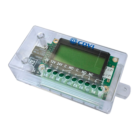
  9. CDVI RADIUM WRW User manual

CDVI RADIUM WRW User manual

Other CDVI Receiver manuals

CDVI RX26-XPL5-GFA User manual

CDVI

CDVI RX26-XPL5-GFA User manual

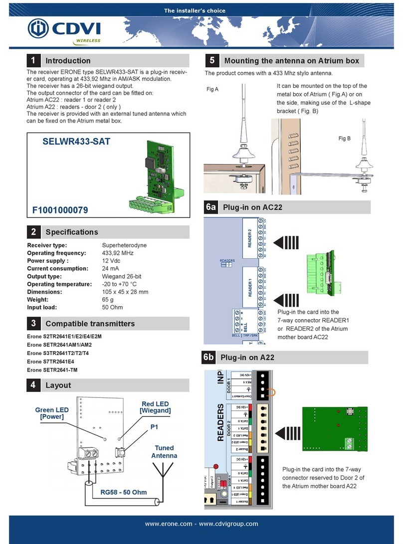
CDVI SELWR433-SAT User manual

CDVI

CDVI SELWR433-SAT User manual

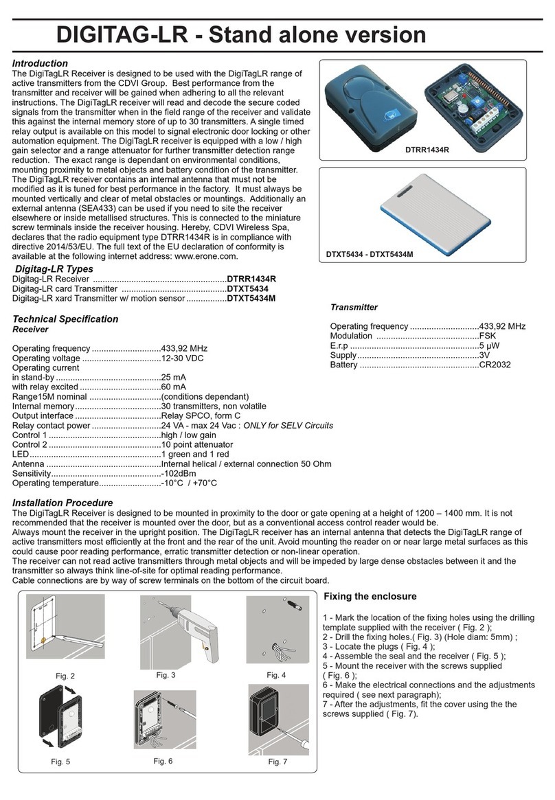
CDVI Digitag LR DTRR1434R User manual

CDVI

CDVI Digitag LR DTRR1434R User manual

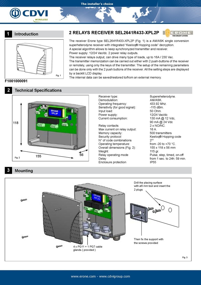
CDVI SEL2641R433-XPL4P User manual

CDVI

CDVI SEL2641R433-XPL4P User manual

CDVI SEL2641R433-XPL User manual

CDVI

CDVI SEL2641R433-XPL User manual

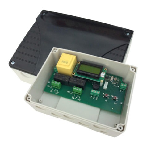
CDVI SEL2641R433-XPL2P User manual

CDVI

CDVI SEL2641R433-XPL2P User manual

CDVI ERONE SEL2641R433-XPL4V User manual

CDVI

CDVI ERONE SEL2641R433-XPL4V User manual

CDVI DIGITAG-LR User manual

CDVI

CDVI DIGITAG-LR User manual

CDVI SEL2641R433-XPL User manual

CDVI

CDVI SEL2641R433-XPL User manual

CDVI DIGITAG-LR DTRR1434R User manual

CDVI

CDVI DIGITAG-LR DTRR1434R User manual

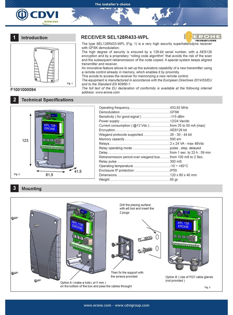
CDVI SEL128R433-WPL User guide

CDVI

CDVI SEL128R433-WPL User guide

CDVI SEL2641R433-XPL5 User manual

CDVI

CDVI SEL2641R433-XPL5 User manual

CDVI SEL2641R433-XPL2V User manual

CDVI

CDVI SEL2641R433-XPL2V User manual

CDVI ERONE SEL2641R433-XPL1V User manual

CDVI

CDVI ERONE SEL2641R433-XPL1V User manual

CDVI SEL2641R433-IP User manual

CDVI

CDVI SEL2641R433-IP User manual

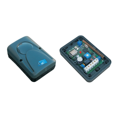
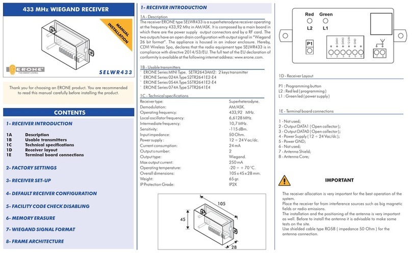
CDVI ERONE SELWR433 User manual

CDVI

CDVI ERONE SELWR433 User manual

Popular Receiver manuals by other brands

Televes ZAS HD SAT user manual

Televes

Televes ZAS HD SAT user manual

Realistic DX-75 Operating and service instructions

Realistic

Realistic DX-75 Operating and service instructions

Saris 4620 Assembly instructions

Saris

Saris 4620 Assembly instructions

Mini DTR 206C PVR user manual

Mini

Mini DTR 206C PVR user manual

RF Elements TwistPort manual

RF Elements

RF Elements TwistPort manual

Denon DN-200WS user guide

Denon

Denon DN-200WS user guide

Yamaha RX-V467 owner's manual

Yamaha

Yamaha RX-V467 owner's manual

Russound SaphIR 858 instruction manual

Russound

Russound SaphIR 858 instruction manual

Quasonix RDMS Firmware update procedure

Quasonix

Quasonix RDMS Firmware update procedure

Pioneer XV-HTD1 Service manual

Pioneer

Pioneer XV-HTD1 Service manual

ATZ HDMI-V2-44HE150 manual

ATZ

ATZ HDMI-V2-44HE150 manual

Sony XNV-770BT MyTomTom Specifications

Sony

Sony XNV-770BT MyTomTom Specifications

Grundig STR 7122 TWIN Service manual

Grundig

Grundig STR 7122 TWIN Service manual

Creative Blaster Modem user guide

Creative

Creative Blaster Modem user guide

Panduit ATLONA AT-OME-RX11 installation guide

Panduit

Panduit ATLONA AT-OME-RX11 installation guide

VOLTCRAFT UTPS-40 operating instructions

VOLTCRAFT

VOLTCRAFT UTPS-40 operating instructions

JVC KW-ADV794 instructions

JVC

JVC KW-ADV794 instructions

Litelink VT-1001 operating instructions

Litelink

Litelink VT-1001 operating instructions

manuals.online logo
manuals.online logoBrands
  • About & Mission
  • Contact us
  • Privacy Policy
  • Terms and Conditions

Copyright 2025 Manuals.Online. All Rights Reserved.

The Installer’s Choice
www.cdvi.ca
www.cdvi.ca
RECEIVER INTRODUCTION
The receiver WRW is a superheterodyne receiver
operating at 433,92 Mhz in AM/ASK. It is composed by
a main board in which there are the power supply output
connectors and by a RF card. The two outputs have an
open drain conguration with output signal in “Wiegand
26 bit format”. The appliance is housed in an indoor
enclosure.
SPECIFICATIONS
Receiver type: Superheterodyne
Operating frequency: 433,92 MHz
Power supply : 12 or 24 Vac/dc
Current consumption: 24 mA
Output type Wiegand 26-bit
Operating temperature: -20 to +70 °C
Dimensions: 105 x 45 x 28 mm
Weight: 65 g
WRW
Wireless Receiver with wiegand output
Also available with CDVI or HID built-in proximity badge
Supplied
Antenna
COMPATIBLE REMOTES
R1
1-Button Remote
R2
2-Button Remote
R4
4-Button Remote
DATA0
DATA1
GND
12 24V÷
_
---
P1
L2 L1
123456
78
TERMINAL CONNECTIONS
P1: Programming button
L2: Red led ( Programming )
L1: Green led ( power supply )
1: Not used
2: DATA1
3: DATA0
4: 12 or 24 Vac/dc
5: GND
6: Not used
7: Antenna Shield
(used for SEA433 tuned antenna)
8: Antenna Core
The Installer’s Choice
CDVI 1637 Highway 440 West, Laval, Québec, Canada, H7L3W3
Tel: (450) 682-7945, Toll Free Tel: 1-866-610-0102, Fax: (450) 682-9590, Toll Free Fax: 1-866-682-9590
Specications may change without prior notice. Printed in Canada - November 2013
DISABLING FACILITY CODE VERIFICATION
When disabling facility code verication, the receiver will accept any
facility code and mantains the check on the key button.
Do the following to disable facility code verication:
1) Press P1 button until the L2 LED turns on and then release it
( Fig. 1a).
2) Within 1 sec. press P1 again. At this point the L2 LED starts to
blink for 5 sec. then switches off . Facility code verication is
now disabled.( Fig. 1b)
Facility code (FC):
001
Serial Number(SN):
28886
FC001 SN28886
OPERATION
The information contained in the frame sent by a remote is
mainly composed by 4 main parameters: Manufacturer Key,
Serial Number, Facility code and Button type. The receiver
accepts only remotes having the right Manufacturer Key. Once
initialized, it sends out in wiegand format the Serial Number and
the Facility code of the remotes. No information of the button
pressed is present in the wiegand signal.
NOTE : No wiegand signal is carried out from the receiver
unless a initialization procedure is performed.
The receiver is capable to store up to 50 different combinations:
“Facility code - Button type”. The button type of each remote can
be A, B, C, D. Combinations of this type can be, for example:
001-A, 001-B, 002-B, 003- B, 010-D, where 002 is the Facility
code and B is the remote button and so on. Combinations as
A+B or C+D are not allowed.
FACILITY CODE AND SERIAL NUMBER LOCATION
FACILITY CODE (FC)=001
A B C D
Serial Number = 28886
The maximum remote ( serial number ) depends on the
access control system capacity
A
AA
BB
C D
REMOTE BUTTON PROGRAMMING
1) Press P1 until L2 LED turns ON
2) Press a remote key button
3) The L2 LED turns off and then makes a short ash.
Any operation not allowed ( memorization with full
memory, memorization of already stored codes ) will
cause 2 quick ashes of L2 LED.
WARRANTY
The warranty period for this product is 60 months, beginning from the manufacturer
date. During this period, if the product does not work correctly, due to a defective
component, the product will be repaired or substituted at our discretion. The
guarantee does not cover the plastic container integrity. After-sale service is
supplied at the factory.
!
IMPORTANT
Receiver location is crucial for optimal system performance. Place
the receiver far from interference sources such as magnetic elds or
radio emissions (neon ballasts, electric motors, etc.). Ensure quality
signal reception by doing range tests before permanently mounting
the receiver.
MANUFACTURED BY CDVI WIRELESS - ITALY
IS-WRWCDUK REV.2 ON 20/2/2017
LED INDICATORS
A 1 second ash of L2 indicates a valid signal reception. A quick
ash of L2 indicates an invalid signal reception
MEMORY RESET (FACTORY DEFAULT)
The procedure allows to erase the receiver memory
1) Press P1 until L2 LED turns on.
2) Release P1 and then press it again until L2 LED starts to ash
3 times
At this point all settings are erased and the receiver is reset to
factory default.
L2 ON L2 BLINKS x 5 sec.
1 A 1 B
RESTORING FACILITY CODE VERIFICATION
Do the following to restore the facility code verication:
1) Press P1 button until the L2 LED turns on and starts to blink
then release it ( Fig. 2a)
2) Within 1 sec. press P1 again. At this point the L2 LED comes
back steady for 5 sec. then switches off ( Fig. 2b). Facility
code verication enabled.
L2 BLINKS2 A 2 B L2 ON x 5 sec.
NOTE : The above Facility code verication can be disabled or
restored only if the receiver has been initialized, that means unless
one remote button has been authorized.