manuals.online logo
Brands
  1. Home
  2. •
  3. Brands
  4. •
  5. CEECO
  6. •
  7. Telephone
  8. •
  9. CEECO SSP-570-D User manual

CEECO SSP-570-D User manual

Other CEECO Telephone manuals

CEECO SSW-323-F User manual

CEECO

CEECO SSW-323-F User manual

CEECO WPP-531-D User manual

CEECO

CEECO WPP-531-D User manual

CEECO MHW-341-D User manual

CEECO

CEECO MHW-341-D User manual

CEECO SSP-351 series User manual

CEECO

CEECO SSP-351 series User manual

CEECO SSP-350-X-130 User manual

CEECO

CEECO SSP-350-X-130 User manual

CEECO SSP-350-X-128 User manual

CEECO

CEECO SSP-350-X-128 User manual

CEECO SSP-571-D User manual

CEECO

CEECO SSP-571-D User manual

CEECO SSP-561-D User manual

CEECO

CEECO SSP-561-D User manual

CEECO WPP-333-F User manual

CEECO

CEECO WPP-333-F User manual

CEECO SSW-521-D User manual

CEECO

CEECO SSW-521-D User manual

CEECO SSP-571-D User manual

CEECO

CEECO SSP-571-D User manual

CEECO SSP-550-D User manual

CEECO

CEECO SSP-550-D User manual

CEECO SSP-511-F User manual

CEECO

CEECO SSP-511-F User manual

CEECO SSP-560-F User manual

CEECO

CEECO SSP-560-F User manual

CEECO HOB-531-X User manual

CEECO

CEECO HOB-531-X User manual

CEECO BLC-303-F User manual

CEECO

CEECO BLC-303-F User manual

CEECO SSP 361-D User manual

CEECO

CEECO SSP 361-D User manual

CEECO SSW-521-X-ADA User manual

CEECO

CEECO SSW-521-X-ADA User manual

CEECO SSW-321-Dr1 User manual

CEECO

CEECO SSW-321-Dr1 User manual

CEECO WPP-331-F User manual

CEECO

CEECO WPP-331-F User manual

CEECO SSP-363-D User manual

CEECO

CEECO SSP-363-D User manual

CEECO SSP-361-X User manual

CEECO

CEECO SSP-361-X User manual

CEECO SSP-363-F User manual

CEECO

CEECO SSP-363-F User manual

CEECO SSW-321-Xr1 User manual

CEECO

CEECO SSW-321-Xr1 User manual

Popular Telephone manuals by other brands

Philips BaseLine Pro manual

Philips

Philips BaseLine Pro manual

V-tech i6772 user guide

V-tech

V-tech i6772 user guide

BT FREELANCE XD 5100 quick start guide

BT

BT FREELANCE XD 5100 quick start guide

Uniden 1360 user guide

Uniden

Uniden 1360 user guide

Fanvil D800 user manual

Fanvil

Fanvil D800 user manual

Avaya IP500 user guide

Avaya

Avaya IP500 user guide

NEC Univerge SV9100 installation manual

NEC

NEC Univerge SV9100 installation manual

Amanda MiniSOHO Installation and programming manual

Amanda

Amanda MiniSOHO Installation and programming manual

Hitachi SelecSet 900 Series user guide

Hitachi

Hitachi SelecSet 900 Series user guide

mPTech HAMMER BS21 quick start guide

mPTech

mPTech HAMMER BS21 quick start guide

NEC 2000IVX user guide

NEC

NEC 2000IVX user guide

ooma Phone Genie quick start guide

ooma

ooma Phone Genie quick start guide

Siemens Gigaset S450 user guide

Siemens

Siemens Gigaset S450 user guide

Clarity RC100 operating instructions

Clarity

Clarity RC100 operating instructions

GE 2-9480 user guide

GE

GE 2-9480 user guide

Geemarc PHOTOPHONE 155 user guide

Geemarc

Geemarc PHOTOPHONE 155 user guide

Interquartz Gemini IQ333 operating instructions

Interquartz

Interquartz Gemini IQ333 operating instructions

SSS Siedle HT 840-0 operating instructions

SSS Siedle

SSS Siedle HT 840-0 operating instructions

manuals.online logo
manuals.online logoBrands
  • About & Mission
  • Contact us
  • Privacy Policy
  • Terms and Conditions

Copyright 2025 Manuals.Online. All Rights Reserved.

SSP-570-D-LPSPKRPCBATD11-ISSUE4.0
SERVICE MANUAL
FOR
MODEL SSP-570-D
HANDS FREE ELEVATOR PHONE
EQUIPPED WITH LOW-POWER SPEAKER BOARD
Serving the Telephone Industry Since 1930
Communication Equipment 519 W South Park Street
& Engineering Company Okeechobee, FL 34972
Voice: 863-357-0798
Fax: 863-357-0006
ISSUE 4.0
CEECO
Communication Equipment & Engineering Company
PROPRIETARY
2
IMPORTANT INFORMATION
FOR
CUSTOMER
Please fill in before you continue.
The following information is necessary when calling CEECO for assistance.
MODEL NUMBER MODEL SSP-570-D, EQUIPPED WITH LOW-POWER
SPEAKER BOARD AND ATD-11 TONE DIALER
SERIAL NUMBER
DATE MANUFACTURED
LOCATION INSTALLED
For us to better serve you, please have this information available when calling for
technical support.
CEECO
Communication Equipment & Engineering Company
519 W South Park Street
Okeechobee, FL 34972
863-357-0798- telephone
863-357-0006- facsimile
[email protected]
www.ceeco.net
ISSUE 4.0
CEECO
Communication Equipment & Engineering Company
PROPRIETARY
3
TABLE OF CONTENTS
SECTION PAGE
1.0 INTRODUCTION………………………………………………………………4
2.0 GENERAL……………………………………………………………………….4
3.0 PROGRAMMING……………………………………………………………….5
4.0 TESTING/OPERATION………………………………………………………10
5.0 RECOMMENDED TOOLS AND TEST EQUIPMENT…………………….11
6.0 INSTALLATION NOTES AND ASSEMBLY INSTRUCTIONS…………..11
7.0 SPECIFICATIONS…………………………………………………………….13
8.0 PARTS LIST……………………………………………………………………14
9.0 FCC NOTICE…………………………………………………………………..15
10.0 REPAIR AND RETURN INFORMATION…………………………………..16
11.0 WARRANTY POLICY………………………………………………………...17
ISSUE 4.0
CEECO
Communication Equipment & Engineering Company
PROPRIETARY
4
1.0 INTRODUCTION
The practices in this manual provide installation and maintenance information for
the CEECO Model SSP-570-D Hands Free Elevator Telephone.
The information in this manual is subject to change without notification.
For information not included in this manual, please call or write:
CEECO
Customer Service
519 W South Park Street
Okeechobee, FL 34972
863-357-0798- telephone
863-357-0006- facsimile
[email protected]
www.ceeco.net
2.0 GENERAL
2.1 The CEECO Model SSP-570-D Hands free telephone is a sturdy, vandal
resistant, Stainless Steel Panel Speakerphone. Instead of a hookswitch and
handset, the SSP-570-D has a Press to start/Press to stop button for the
initiation and termination of phone calls. This Emergency Auto Dial
button is provided for one button dialing of preprogrammed number of up
to 11 digits. The telephone is fully line powered, with no battery backup
required for memory retention.Manual volume control is also provided
inside the phone, by way of an adjustable “POT”. The phone may be
programmed to automatically disconnect a call, and/or reset the telephone,
after the expiration of a one (1), three (3), or five (5) minute time period.
Programming is accomplished by way of two (2) hardware mini-jumpers.
The telephone may also be equipped with a red LED to indicate “off
hook” periods.
ISSUE 4.0
CEECO
Communication Equipment & Engineering Company
PROPRIETARY
5
3.0 PROGRAMMING
NOTE: It is recommended that you ground yourself to prevent ESD
damage to the PCB(s).
3.1 The phone can be programmed to automatically disconnect a phone call
after the elapse of a selected period of time (1, 3 or 5 minutes). This is
accomplished through the manipulation of mini-jumpers on the Printed
Circuit Board.
3.2 If the telephone is already secured in its mounting/housing, remove it to
accomplish the programming. This will require the use of the security tool
(P/N 301-037 sold separately).
3.3 The Printed Circuit Board 660-100, which is the larger board has two
plastic mini-jumpers on it. These mini-jumpers are used to program the
Time-Out Disconnect feature. Locate the plastic mini-jumper that has
“JP3” written above it in small white print on the PC board (Please refer
to diagram 3.13 on page 9). Below it, in small white print, appear the
words “ON” and “OFF”. Place the mini-jumper across the middle and far-
left copper pins. This is the "ON" position, which activates the Time Out
Disconnect feature. When the automatic call disconnect feature is not
desired, the jumper should be in the “OFF” position (jumper bridges the
middle and far right copper pins).
3.4 When utilizing the Automatic Call Disconnect feature (Call Time-out), a
choice of 1, 3, or 5 minutes is available. Locate the plastic mini-jumper
on the Printed Circuit Board, which has above it “JP2” in small white
print. Below it are “5”, “3” and “1” also in small white print. Place the
jumper so that it bridges the two copper pins corresponding with your
selection of 1, 3, or 5 minutes. (Please refer to diagram 3.13 on page 9).
3.5 The ATD-11 Automatic Tone Dialer enables the phone to automatically
dial a number of up to eleven digits in length. The auto-dial phone
number is programmed into the phone through the manipulation of mini-
jumpers on the ATD-11 printed circuit board, which is the smaller board
in the phone. A paired of small needle nose pliers may be helpful with
moving the mini-jumpers; however, you must be very careful not to touch
the circuit boards with the pliers, as this may cause damage. Programming
is accomplished as described in the sections that follow.
ISSUE 4.0
CEECO
Communication Equipment & Engineering Company
PROPRIETARY
6
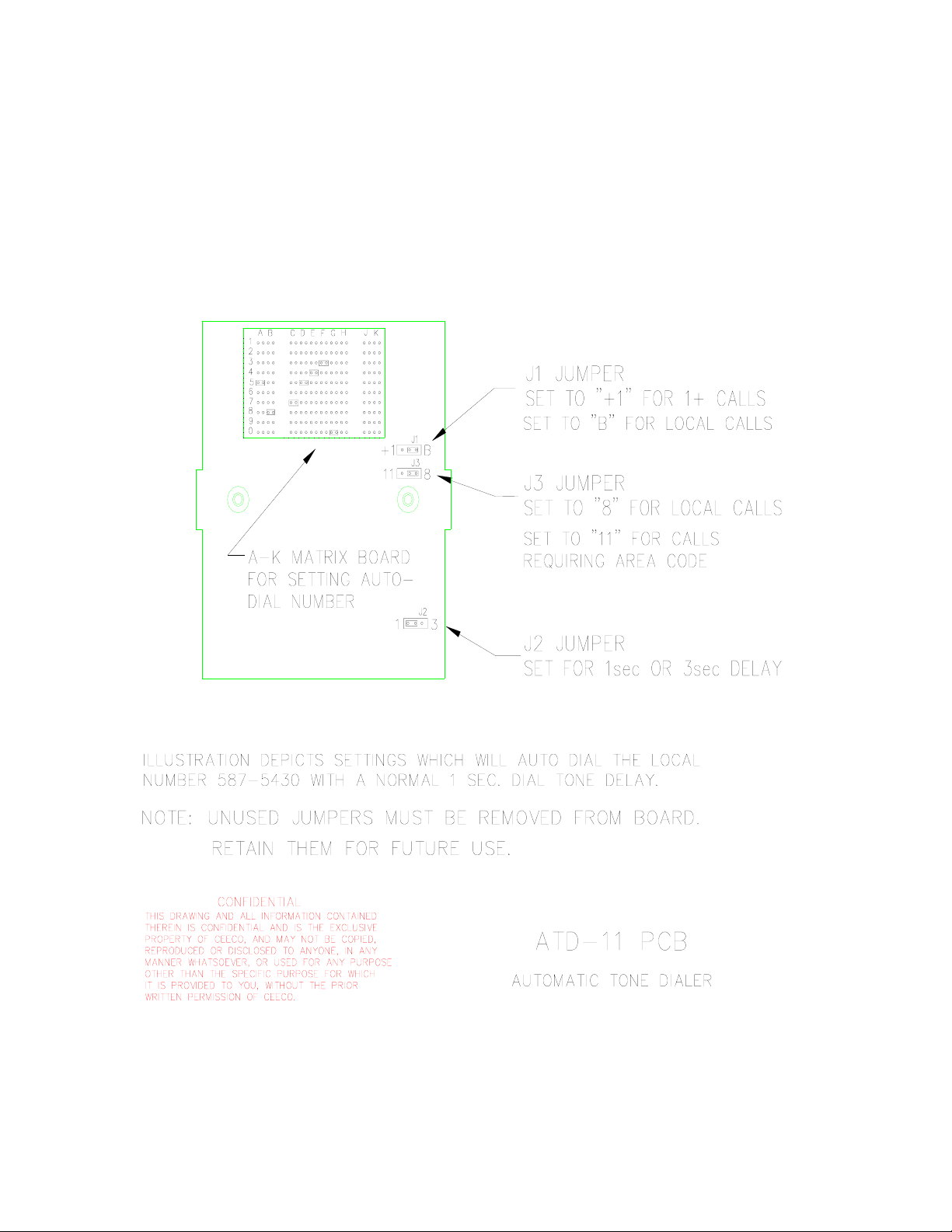
3.6 If the number to be programmed is a (1+) or long-distance call, locate the
plastic mini-jumper at the “J1” position location of the ATD-11 printed
circuit board. The ATD-11 circuit board has a smaller board mounted to
it, which has several rows and columns of copper contacts/pins on it. The
“J1” position you are looking for is located just below the bottom right
hand corner of that smaller piggyback board. The “J1” position has three
copper contacts/pins, with a plastic mini-jumper, and is readily identified
by the “+1” that appears on the board in small white print just to its left.
By moving the plastic mini-jumper so that it bridges the middle copper pin
and the far left or “+1” pin, you will cause the digit “1” to automatically
dial out prior to any other programmed number. If your desired number is
local or does not need a preceding one, then move the mini-jumper to
bridge the middle copper pin and the far right pin. You will observe a “P”
in small white print on the circuit board just right of this right hand pin.
(Please refer to diagram 3.12, on page 8).
3.7 Next, locate the plastic mini-jumper at the “J3” position of the circuit
board, which is just below the “J1” position. It could also be considered
the second plastic mini-jumper below the bottom right hand corner of the
small piggyback board. Just left of this “J3” position, in small white print,
appears “11”, bridging the middle and far left corner pins. The “J3” mini-
jumper should always be in this position, regardless of the number you are
programming. (Refer to diagram 3.12 on page 8).
3.10 Now let’s program the number to be automatically dialed. Looking at
the piggyback circuit board containing several rows and columns of
copper pins, you will see ten plastic mini-jumpers. The rows are labeled
1 thru 0 on the left side of the circuit board. The columns are labeled A
thru K across the top of the circuit board and the columns of copper pins
are in pairs. Each pair of copper pins represents a number to be dialed.
For example, let’s assume that you want to program the phone to dial 1-
954-587-5430. Place the plastic mini-jumper under column “A” across
the two copper pins that align with row “9”. Place the mini-jumper under
column “B” so that it bridges the pair of copper pins in row “5”. Place the
mini-jumper under column “C” across the pair of copper pins in row “4”
and so on, until the entire number is programmed. Each column
represents a digit, so do not skip any. This example happens to include a
long distance number, so you would move the “J1” jumper to the “+1”
position. If your desired number were short, like 911 for example, the
programming would be slightly different. In a case such as that, you
would place the jumper under column “A” in the “9” position and the
jumpers under columns “B” and “C” in the “1” position. You would then
remove the seven remaining black plastic mini-jumpers, with the
exception of positions J1, J2 & J3, so that no erroneous digits dial out.
ISSUE 4.0
CEECO
Communication Equipment & Engineering Company
PROPRIETARY
7
PROGRAMMING CONTINUED…
3.11 Be sure each mini-jumper is properly positioned to make good contact and
dial the intended number. Do not discard unused mini-jumpers, as you
may need them in the future. It may be wise to tape them to the inside of
the phone somewhere out of harms way.
3.12 There is one last mini-jumper location that has not been addressed yet.
This jumper is positioned at the time of manufacturing to accommodate
most telephone environments. If your telephone line delivers dial tone to
your phone in one second or less, then you should ignore this section. If
you happen to be in a long loop environment, which takes more than one
second to deliver dial tone on the line, then you will need to locate the
plastic mini-jumper located at the “J2” position of the ATD11 board. The
“J2” position can be found approximately 1.5” – 1.75” directly below the
“J1” and “J3” positions and is somewhat by itself. Position the “J2”,
plastic mini-jumper, so that it bridges the middle and far right copper pins.
A “3” appears in small white print just right of this position. Placing the
jumper there will cause the phone to delay 3 to 4 seconds before dialing.
This should allow the phone to accommodate those extra long loop
situations in terms of time to receive dial tone
3.11 Programming is now complete and the telephone is ready for
Testing/Operation.
ISSUE 4.0
CEECO
Communication Equipment & Engineering Company
PROPRIETARY
8
3.12 PROGRAMMING DIAGRAM FOR THE ADT11- BOARD
ISSUE 4.0
CEECO
Communication Equipment & Engineering Company
PROPRIETARY
9
3.13 PROGRAMMING DIAGRAM FOR THE LOW-POWER BOARD
CONFIDENTIAL
This drawing and all information contained
therein is confidential and is the exclusive
property of CEECO and may not be copied,
reproduced or disclosed to anyone, in any
manner whatsoever, or used for any purpose
other than for which it is provided to you,
without the prior written permission of
CEECO.
ISSUE 4.0
CEECO
Communication Equipment & Engineering Company
PROPRIETARY
10
4.0 TESTING/OPERATION
Action: Connect the phone to a working telephone line or DTMF test set.
Press the "CALL" button.
Reaction: Dial tone. Red LED illuminates (If equipped)
The preprogrammed number is automatically dialed.
Action: The called party answers.
Reaction: A normal speakerphone conversation is allowed.
Action: Finish the conversation and press the "CALL" button to hang up.
Reaction: Red LED goes out. (If equipped) and the call is terminated. If you
do not hang up the phone it will automatically disconnect if you
programmed it as such.
Action: Place a call to the telephone from another telephone.
Reaction: The telephone rings. Press the “CALL” button to answer the call.
The red LED illuminates (if equipped). The pre-programmed
number will dial out, but should be ignored. A normal
speakerphone conversation is allowed.
Action: Finish the conversation and press the “CALL” button to hang up.
Reaction: The red LED goes out, (if equipped) and the call is terminated. If
the phone is not hung up, it will automatically disconnect if it has
been programmed as such (refer to section 3.0).
5.0 RECOMMENDED TOOLS AND TEST EQUIPMENT
Security Tool, CEECO part number 301-037
Insulated Needle Nose Pliers
Flat Blade /Phillips Head Screwdriver
Volt/Ohm Meter