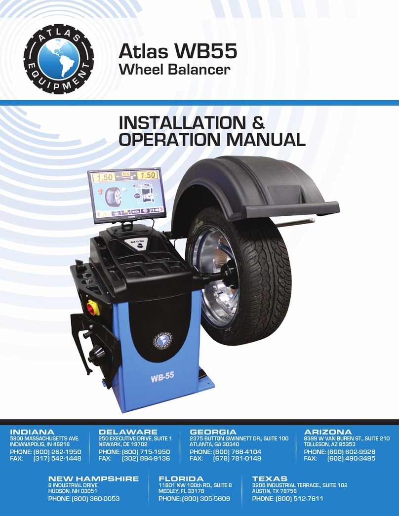
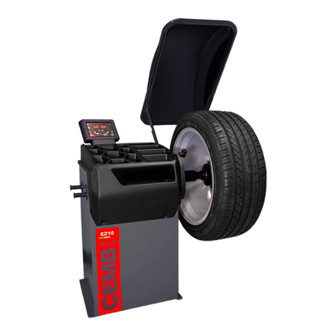
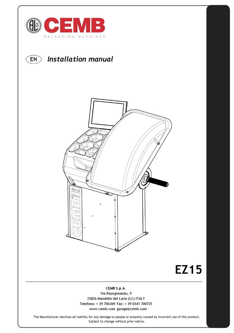
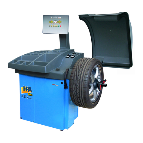
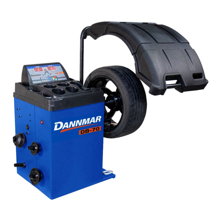
CEMB EZ10 User manual

Installation manual
EZ10
CEMB S.p.A.
Via Risorgimento, 9
23826 Mandello del Lario (LC) ITALY
Telefono: + 39 706369 Fax: + 39 0341 700725
www.cemb.com [email protected]
The Manufacturer declines all liability for any damage to people or property caused by incorrect use of this product.
Subject to change without prior notice.

Istruzioni originali
Translation of the original instructions
Traduction de la notice originale
Übersetzung der Originalanweisungen
Traducción de las instrucciones originales
Tradução das instruções originais

Contents
EN
Installation manual
ENGLISH
1. INTRODUCTION 2
1.1 GENERAL 2
2. SAFETY RULES 2
2.1 GENERAL NOTES 2
2.2 SYMBOLS 2
2.3 DEFINITIONS OF “OPERATOR” AND “SPECIALISED TECHNICIAN” 3
2.4 PERSONAL PROTECTION DEVICES (PPD) 3
2.4.1 Protection devices to wear 3
2.5 GENERAL WARNINGS 4
2.6 EMERGENCIES 4
2.6.1 First aid 4
2.6.2 Fire-ghtingmeasures 4
2.7 AIRBORNE NOISE EMISSION 5
2.8 OPERATOR WORKING POSITION 5
3. UNPACKING AND POSITIONING 6
3.1 VISUAL INSPECTION 6
3.1.1 Checkingthemachineandequipmentsupplied 6
3.2 UNPACKING 6
3.3 PACKING LIST 7
3.4 STORAGE 7
3.5 HANDLING 7
3.5.1 Removingthepallet 8
3.6 POSITIONING 8
3.6.1 Warningsforpositioning 8
4. INSTALLATION 9
4.1 CLEANING 11
4.2 AMBIENT CHARACTERISTICS 11
4.3 FITTING THE ADAPTERS 11
4.4 ELECTRICAL CONNECTION 14
4.4.1 Safetyrules 14
4.4.2 Connection 14
4.5 PNEUMATIC CONNECTION 14
5. RESIDUAL RISKS 15

ENGLISH
Installation manual Ver. 05-2017
2
1. Introduction
1.1 GENERAL
The machine has been constructed in conformity with the current EC Directives and the technical standards im-
plementing the requirements, as stated in the declaration of conformity issued by the manufacturer and attached
to the manual. This publication, hereinafter simply referred to as ‘manual’, contains all the information for safe
installation of the machine stated in the declaration of conformity.
This manual addresses operators previously instructed on the precautions to adopt when working in the presence of
electrical power and moving devices as well as on manual load handling which imposes that loads handled manually
may not exceed 30 kg for men and 20 kg for women. Should the weight of the wheels to be balanced exceed the
permitted limits, all our balancing machines can be supplied with a lift to facilitate tyre mounting/dismounting,
as an option or standard based on the model. The manual addresses operators instructed on the precautions to
take in relation to the presence of electric current and moving devices. This publication is intended for all ‘users’
who as far as within their competence need to and/or are obliged to give instructions to others or operate on the
machine themselves.
The original Italian text of this publication constitutes the only reference to resolve any interpretation controver-
sies related to the translation into the European Community languages.
This publication forms an integral part of the machine and must therefore be kept for future reference until final
2. Safety rules
2.1 GENERAL NOTES
WARNING
The machine has been designed and constructed in observance of the CE requirements taking into account normal
and reasonably foreseeable use.
The machine has been constructed for the application stated in the user manual attached hereto.
It is not permitted for any reason whatsoever to use the machine for purposes different from those for which it
was designed nor to use it in ways different from those described in this manual.
The various operations must be performed according to the criterion and the chronology described in this manual.
2.2 SYMBOLS
Throughout this manual dangerous operations are highlighted with graphic symbols to draw the reader’s attention.
Thefollowinggraphicsymbolsareused:
WARNING
dismantling and scrapping of the machine. For installation, startup and use of the machine, the user must comply
with the specific workplace legislation in force in the country where the machine is installed.
Safety rules

ENGLISH
Installation manual Ver. 05-2017
3
INFORMATION
Thiswarningindicatesimportantinformationwhichmustbecarefullyread.
2.3 DEFINITIONS OF “OPERATOR” AND “SPECIALISED TECHNICIAN”
Any professional person who is to access the machine for operation and routine maintenance is defined as an “op-
erator”. This means persons who have knowledge of the operating and maintenance procedures of the machine
and have the following qualifications:
1. training that authorises operation according to the safety standards in relation to the risks deriving from the
presence of electrical power and moving devices and the risks related to manual load handling;
2. trained to use the personal protection devices and basic rst aid training.
The employer must assign a suitable person to operate the machine in accordance with the laws in force, assess-
ing his or her psycho-physical health, personal education, training and experience, as well as knowledge of the
standards, requirements and provisions for accident prevention.
In addition, the operator assigned based on the above must be specifically trained for use of the machine and any
accessories.
Finally, the operator must read through this manual.
2.4 PERSONAL PROTECTION DEVICES (PPD)
WARNING
The persons that are to operate on and/or work in proximity of the machine may not wear clothes with wide sleeves,
laces, belts, bracelets or anything else that may pose a potential risk. Long hair must be tied up to prevent any risk.
2.4.1 Protection devices to wear
The following protection devices must be worn.
Insulated safety shoes with rubber sole
and reinforced tip
Use: always
(EN345)
(ANSI Z41.1-1991)
(OSHA,1910.136)
Protective gloves
Use: always
(EN388)
(ANSI/ISEA105-2005)
(OSHA,1910.138)
Goggles
Use: always
(EN166 1F)
(ANSI Z87.1)
(OSHA,1910.133)
Working clothes
Use: always
(EN510) (OSHA,1910.132)
Safety rules

ENGLISH
Installation manual Ver. 05-2017
4
2.5 GENERAL WARNINGS
WARNING
▪The machine must be installed, maintained and used according to the instructions given in this manual and ac-
cording to the procedures given from case to case.
▪The employer must train the operators for safe installation, use and maintenance of the machine.
▪Only specialised and specifically trained persons are to be allowed access to the machine for any extraordinary
maintenance operation.
▪Before operating on the electrical parts of the machine cut the power.
▪For the duration of maintenance, “Work in progress” signs must be posted in the department in such a way
that they are visible from all the access areas.
▪Always operate with due caution and wear the personal protection devices (PPD).
▪The machine (and any accessory devices) must always be connected to earth to discharge short-circuit currents
and electrostatic voltages. The mains voltage must correspond to the value shown on the machine identication
plate. It is inadvisable to use cable extensions/socket adaptors. When the machine is not used, disconnect it from
the mains by pulling the plug from the socket.
▪Before carrying out any operation stop the machine.
▪In the event of fire, do not use water but only powder or carbon dioxide fire extinguishers.
▪It is strictly prohibited to deposit combustible material in the vicinity of the machine.
▪Do not deactivate the safety devices or ignore warnings and alarms, be they communicated by the software or
by warning labels fixed on the installation. Should the plates, adhesive labels, decals or any other warning sign
on the machine deteriorate they must be replaced.
▪It is not permitted for any reason whatsoever to modify, tamper with or alter the machine structure, the devices
fitted, the operating sequence, etc. without prior consultation with the manufacturer.
▪All the routine and extraordinary maintenance operations must be recorded in the logbook noting down the
date, time, type of operation, name of the operator and any other useful information.
▪In the event of faults or malfunctioning, contact your local distributor or the manufacturer. All the repair opera-
tions must be performed by qualified technicians.
▪It is strictly prohibited to clean the internal and external electrical parts of the wheel balancer with water.
▪Exclusively use alcohol to clean the machine. Do not use any other chemical product. Do not under any circum-
stances blast with compressed air.
▪Do not leave the machine exposed to the rain or the elements. The ambient storage and operating conditions
must meet the requirements set out in the chapter INSTALLATION.
▪In the event of failure, deformation or malfunctioning of the safety devices, immediately replace them; “Make-
shift” repairs are strictly prohibited. Use only original spare parts for which the machine has been designed
and constructed.
▪The machine and the workplace must be kept perfectly clean.
▪When the maintenance operations have been completed, before restoring the power supply, carefully check that
you have not forgotten tools and/or other materials in the machine operating area. In any event, also during
operation, no object may be placed on the protection shield.
Safety rules

ENGLISH
Installation manual Ver. 05-2017
5
2.6 EMERGENCIES
2.6.1 First aid
For any first aid follow the corporate regulations and conventional procedures.
2.6.2 Fire-fighting measures
Do not use water to extinguish fires, but only powder or carbon dioxide extinguishers. Preferably use extinguishers
filled with a special powder for metal fires.
2.7 AIRBORNE NOISE EMISSION
The machine noise, measured with the machine empty, is constantly contained at levels below 70 dB(A).
During operation the machine noise is subordinate to the background noise in the workplace, the presence of other
machines and other factors that cannot be assessed by the manufacturer in advance.
The user therefore needs to make a phonometric measurement of the noise emitted by the machine during normal
operation, and provide for personal protection devices (headsets) if the noise emission exceeds the threshold laid
down in the regulations in force in the country where the machine is used.
2.8 OPERATOR WORKING POSITION
During balancing the operator must stand in front of the control console and avoid standing in front of the wheel
during the balancing cycle.
Safety rules

ENGLISH
Installation manual Ver. 05-2017
6
3.1 VISUAL INSPECTION
The packaging must be intact upon receipt, i.e.:
▪there must not be any sign of collision or breakage;
▪there must not be any sign that it was exposed to sources of heat, ice,
water, etc...;
▪there must not be any sign of tampering.
Any deformations indicate that the machine was knocked about during
transport and may compromise proper machine functioning.
3.1.1 Checking the machine and equipment supplied
The main body of the machine, the relative accessories and the equipment
supplied (as agreed with the manufacturer) must be in perfect condition.
The supply is carefully checked before shipment, nevertheless it is advis-
able to check upon receipt that it is complete and in order.
Check that:
▪the shipping data (addressee, number of packages, order number, etc.) correspond to the accompanying docu-
mentation;
▪the technical-legal documentation provided with the machine includes the instruction manual for the type of
machine to be installed as well as the EC declaration of conformity or, alternatively, the declaration of the
Manufacturer.
Intheeventofdefectsand/ormissingmaterialimmediatelynotifythemanufacturerandfollowhisinstructions
beforeproceedingwithinstallationandstartup.
3.2 UNPACKING
To remove the packaging refer to the “arrow” shown on the outside box.
Operateasfollowstounpackthemachine:
1. cut the plastic safety straps;
2. open the top of the cardboard box;
3. remove the top protection;
4. remove any protective corner pieces;
5. remove the cardboard box pulling it upward;
6. remove any protective “pluriball”;
7. inspect the machine to check for any damage. Immediately inform the carrier and the supplier in the event of
apparent damage.
Keep the packaging materials for possible future shipment of the machine.
ThepackagingusedisincompliancewiththeenvironmentalrequirementssetoutintheEuropeanpackagingregulations
(OfficialECGazette,N.L.365/19).Thecardboardboxescaneasilyberecycled.Theplasticwrappingsaremadeof
materialsfreeofhazardousmetals.Itisadvisabletocontactthecompetentlocalauthorityfortheirdisposal.
3. Unpacking and positioning
Unpacking and positioning

ENGLISH
Installation manual Ver. 05-2017
7
3.3 PACKING LIST
All the materials included in the supply are listed on the packing list. The contents may vary from machine to
machine depending on the sales agreements, the optional parts supplied, etc.
Generally,thesupplyincludes:
▪the machine
▪the toolbox
▪the instruction manual
3.4 STORAGE
Whenthemachine:
▪is not immediately installed;
▪is uninstalled and stored pending moving to another place
position it in a covered place protected against direct contact with atmospheric agents and dust.
The permitted ambient values in the storage area are as follows:
▪Temperature:+5to+40°C(41-104°F)
▪Relativehumidity:30÷80%.
If taking the machine out of service after a period of use and after performing the necessary maintenance opera-
tions, it can be stored for a period of provided that it is stored in a closed dust-free
environment without aggressive agents and with the following characteristics:
▪Ambient conditions as described above
▪Positioned in such a way that it is protected against deformation, crushing, breakage, etc.
▪Not subjected to knocks, vibrations, overhanging loads, etc.
3.5 HANDLING
The term “handling” means unloading the machine from the means of
transport and positioning it in the place where it will be used. Upon
receipt the customer needs to unload the machine using his own means
and store it in a dry and protected place pending installation.
The machine is to be handled while still fastened on the wooden pallet
(see next paragraph) by suitably trained persons wearing the personal
protection devices described in Chapter 2.
WARNING
Before lifting the machine with a lift truck or transpallet, make sure that the forks are properly positioned and
protrude from the opposite side by at least 30 cm.
Unpacking and positioning

ENGLISH
Installation manual Ver. 05-2017
8
3.5.1 Removing the pallet
The machine is secured to a base pallet. Prepare an adequate area with level flooring and mark it off before lifting
the machine and positioning it on the ground.
To remove the machine from the pallet operate as follows:
▪Remove the screws that lock the machine to the pallet
(figure on the side)
WARNING
manual handling and lifting of the machine must be carried out with the aid of a lift truck. prise on the base near the 3 support
points as shown in the figure below. Other points, such as the head or the accessory tray, must not be forced under any circumstances.
3.6 POSITIONING
3.6.1 Warnings for positioning
The machine must be positioned respecting the following conditions:
Unpacking and positioning
▪the humidity and the temperature must be within the prescribed
limits (see paragraph 4.2);
▪the fire-fighting measures must be respected;
▪allow for sufficient space at the front, side and rear of the machine
for service or periodic maintenance and at the same time to assure
adequate air circulation. It is advisable to leave a space of about 1
metre around the machine;
▪the place where the machine is installed must be free of corrosive/
explosive powders or gas;
▪the place of installation must be vibration-free;
▪the lighting must be such that the various machine functions can
clearly be seen;
▪lift the machine and position it correctly in its final position (figure
on the side);
▪the machine must stand on a flat rigid surface and possibly away from
any joint in the floor;
▪the machine functions properly without having to fasten it to the floor
with wheels weighing up to 35 kg; for heavier wheels, fasten it at the
points indicated (figure on the side).
According to UNI EN 10380 regulations, the lighting for a generic working area (such as control rooms, fixed work-
stations in production plants, etc.) must on average be 300 lux (acceptable values between 200 and 500 lux). If the
machine is installed in a country different from Italy, the specific regulations in that country must be followed.
The lighting system must be such as to guarantee average lighting of 300 lux for the working environment. This
value depends on various factors, such as the characteristics of the working environment (more or less reflecting
walls and ceiling, height of the light points, etc.) and the type of bulbs used.

ENGLISH
Installation manual Ver. 05-2017
XX XX
XX XX XX
XX XX
XX XX XX
9
4. Installation
WARNING
USA)
Installation

ENGLISH
Installation manual Ver. 05-2017
Hz
KW
VERSION
MODEL
SER.N°
V
PHASE
Year
T
°C
[
[
V
A
XXXXX
04PRB0568
XXXXX
10 Installation

ENGLISH
Installation manual Ver. 05-2017
11
WARNING
Before starting the machine, clean off any dust, foreign matter and soiling that may have accumulated during
transport. Use alcohol to clean the plastic parts.
WARNING
The operating environment must have the following characteristics:
▪Temperature:
▪Maximum relative humidity:
The machine may not be used in open places and/or exposed to atmospheric agents or in environments with cor-
rosive and/or abrasive vapours, fumes or dust with the risk of fire or explosion, and in any case where the use of
explosion-proof components is prescribed. In addition, for machines equipped with SONAR (LA-EMS-LR), air currents
or forced ventilation in the direction of the device may cause malfunctions or incorrect readings.
WARNING
Before fitting the end piece to the wheel balancer, thoroughly
clean the machine shaft and the adapter hole. Any traces
of dirt or incorrect locking may affect balancing accuracy.
The wheel balancer is supplied complete with adapter and
cones for fastening wheels with a central hole. The threaded
end must be fitted during machine installation using the Al-
len wrench provided applying the correct tightening torque
(20-25Nm). If it is a machine with pneumatic locking, follow
the procedure indicated in the next pages. In both cases, it
can be removed for fitting any optional adapters.
WARNING
Installation

ENGLISH
Installation manual Ver. 05-2017
SE2-MOUNTING
A B
CD
E
Si raccomandatassativamentelavericaperiodica(mensile)delcorrettoserraggiodelterminaleSE2(780Nm575FtIbs).
UnserraggioerratopuòprovocareimprecisionidiequilibraturaedanniallamacchinaNONCOPERTIDAGARANZIA.
Westronglyrecommendaperiodic(monthly)testingofthepropertighteningoftheSE2terminal(780Nm575FtIbs).
AbadtighteningcancausebalancinginaccuraciesandmachinedamagesNOTCOVEREDBYWARRANTY.
Nousrecommandonsfortementlavéricationpériodique(mensuel)ducorrectserrageduterminalSE2(780Nm575FtIbs).
Unmauvaisserragepeutentraînerdesimprécisionsd’équilibrageetdommagesàlamachinePASCOUVERTSPARLA
GARANTIE.
Eineregelmäßige(monatliche)KontrollederrichtigenBefestigungdesEndstücksSE2wirdunbedingtempfohlen.
EinefalscheBefestigungkannzueinerungenauenAuswuchtungundzuMaschinenschädenführen,dieNICHTVONDERGARANTIEGEDECKTSIND.
Esmuyrecomendableunapruebaperiódica(mensual)delcorrectoaprietedelterminalSE2(780Nm575FtIbs).
UnmalajustepuedeperjudicarlacalidaddelequilibradoycausardañosalamáquinaNOCUBIERTOPORLAGARANTÍA.
Éaltamenterecomendávelumtesteperiódico(mensal)oapertoadequadodoterminalSE2(780Nm575FtIbs).
UmmauapertopodecausarimprecisõesequilíbrioedanosàmáquinaNÃOCOBERTOSPELAGARANTIA.
0mm
CH13
CH17 (50Nm)
12 Installation

ENGLISH
Installation manual Ver. 05-2017
SE2-DISMOUNTING
AB
CD
E
CH13
CH17
13
Installation

ENGLISH
Installation manual Ver. 05-2017
14
4.4 ELECTRICAL CONNECTION
4.4.1 Safety rules
Beforeperforminganyoperation,readandapplythefollowing:
▪Make sure that the main electric cabinet to which the machine is connected is connected to the earth circuit
and is adequately protected as required by the regulations in force in the country where the machine is in-
stalled.The socket to which the machine is connected must have a slow acting safety switch calibrated to 4 A
(230V) or 8A (115V).
▪Check that the mains voltage and frequency correspond to the values indicated on the machine identification
plate.
▪The socket to which the machine is connected must be dimensioned to support the power absorbed up to a
maxi mum of 1.1 kW.
4.4.2 Connection
The machine is supplied with a single-phase cable to which a plug conform to the regulations must be connected.
If an extension needs to be used, bear in mind that the wire cross-section may not be less than 2.5 mm2. Make
sure that the extension is arranged so that it does not constitute a risk or obstruction.
WARNING
!
IT IS
CEI EN 50110-1 (NFPA.
4.5 PNEUMATIC CONNECTION
If the machine is equipped with a pneumatic locking/release spindle and/or zero weight lift, it needs to be fed
with compressed air at 7-10 bar. The compressed air coupling is positioned on the rear of the machine. The com-
pressed air must be clean and dry. The pipes and pipe fittings must be properly connected by appropriately trained
personnel. The warranty does not cover damage caused by the absence of an adequate air filtration system.
Installation

ENGLISH
Installation manual Ver. 05-2017
15
Residual risks
5. Residual risks
Residual risk means a potential risk impossible to eliminate or partially eliminatable, which may cause injury to
the operator if operating using improper working methods and practices.
▪Pay attention to the position of your hands in the areas indicated
in the figure, as there is a risk of crushing your fingers during
wheel locking on the spindle.
▪While mounting or dismounting the tyre, pay attention to avoid
accidentally crushing your feet.
▪For machines equipped with lift, do not stand in the working
area, as there is a risk of crushing during ascent and descent
of the lift.

ENGLISH
Installation manual Ver. 05-2017
16
Other manuals for EZ10
1
Table of contents
Other CEMB Wheel Balancer manuals