Cirris CH+ User manual
Setting Up the CH+ Tester 1
Use this guide to setup the CH+ tester, install the easy-wire software, checkout the system, get
the overview of the test system, and find more information to use the tester.
Note: Prior to June 1, 2001 the Signature CH+ shipped with the Signature Plus Series
software, which included a complete printed user's manual. The CH+ can now also be
controlled with the easy-wire software, which utilizes this getting started guide and an on-line
help system/manual (included on the easy-wire software CD). There is no printed user's
manual for the easy-wire software.
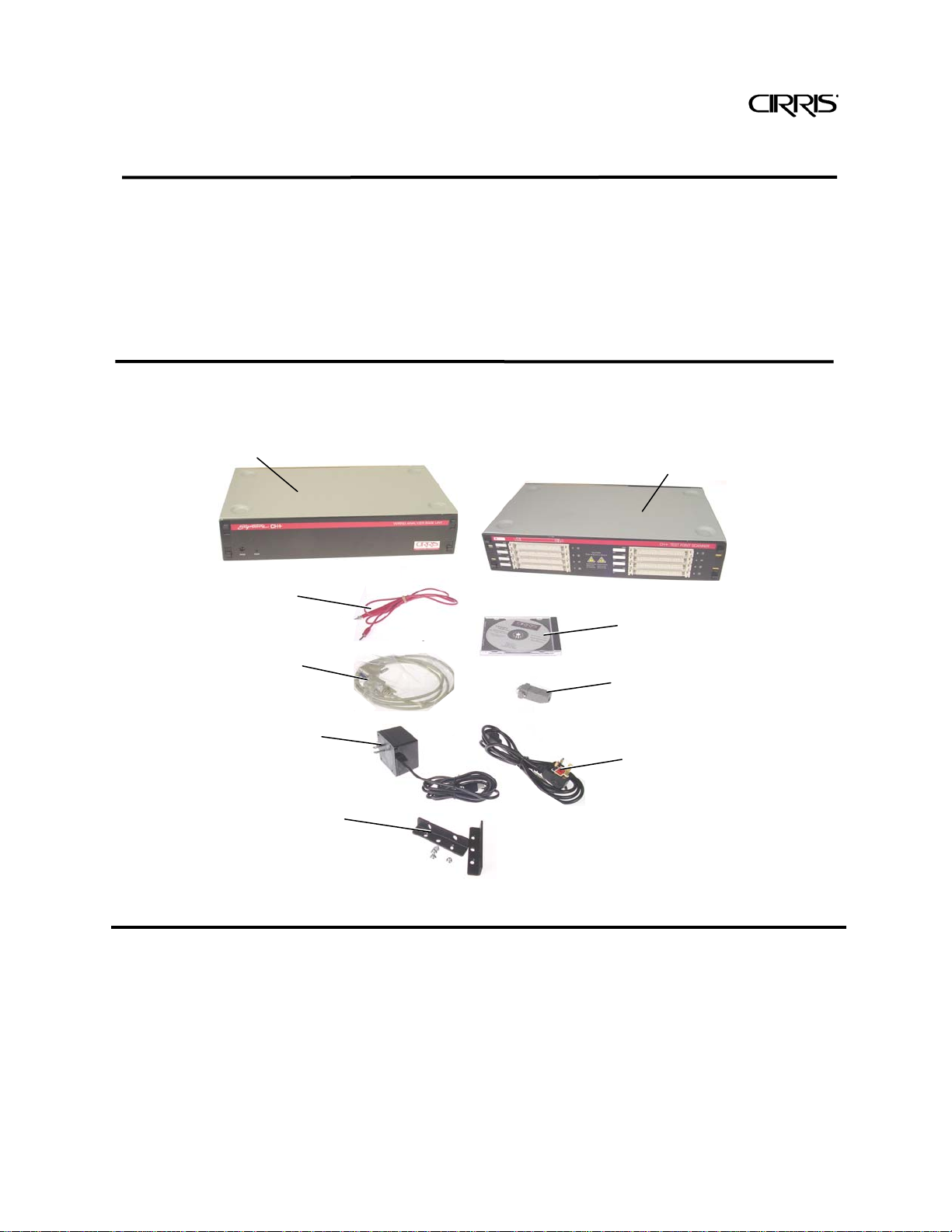
You should have received
For using the Signature CH+ with easy-wire software
CH+ Getting Started Guide
CH+ Base Unit
One required per system.
9-pin Serial Cable
Hand Held Probe
Loop Back Plug
Scanner Test Point Box
One box required per
system. Maximum 21.
Right Angle Mounting
Brackets
Available upon request.
Used for rack mounting
the system.
Power Cord Adapter
Required only for
220V Power systems.
Power Transformer
One required for each
Base unit and Scanner
easy-wire software CD

Setting Up the CH+ Tester 2
Computer Requirements for a Station or Network Server
If you plan on using a Networked Server:
Accessing test data from a network is a nice way to make sure that all the stations on the
production floor use the same test information. The requirements for a network server are the
same as a workstation with the exception that the server must use either 2000 or 2003
Windows Server software. The computer that runs the network database should be dedicated
to running the database software. The network database server should not be used as a
workstation.
You may want to add optional accessories
These accessories can be purchased through computer and office supply stores. Each
accessory is easy to integrate with your computer and CH+ test system.
Sheet Printer
Used to print test
reports and fixturing
information.
Label Printer
Allows printed labels
to be applied to the
tested product.
PC Network Card
Allows the test
stations to share
test information
with each other.
Barcode Scanner
Used on the
production floor
instead of the mouse.
Computer CPU
1.6 GHz or better.
Mouse
Required for installation and
test setup. Can be replaced
with a barcode scanner on the
production floor.
Free Disk Space
Minimum: 5 GB
Recommended: 10 GB
Windows Environment
Windows XP Professional,
Windows 2003 Server, or
Windows 2000 Server
Monito
r
Recommended: 1024X 768
Speaker & Sound Card
Required
Serial Port or USB*
1 Required
*If no serial port, must use
Keyspan USB-to-Serial Adapter USA-
19HS
CD ROM Drive
Required
V
ideo Card
64 Meg On Board Memory
Internet Connection
Not required, but can facilitate
support issues.
RAM
Minimum: 1 GB
Setting Up the CH+ Tester 3
Warning!
Possible electric shock! Please Note
Cirris hipot testers are designed to be safe for operators. Injuries from hipot test equipment
are rare. Still, not every hipot test situation is safe. Hipot testing does not present a danger to
healthy individuals; however, occasional mild electric shock may be experienced. Small
shocks only occur during a hipot test when the operator touches an energized connection
point. Any shock from the tester may result in a hipot test failure.
Medical Warning!
A child or individual wearing a cardiac pacemaker, an insulin pump, or any
electronically controlled medical device should NOT perform hipot testing.
For ideas on improving hipot safety visit:
www.cirris.com/testing/guidelines/hipot_safety.html

Setting Up the CH+ Tester 4
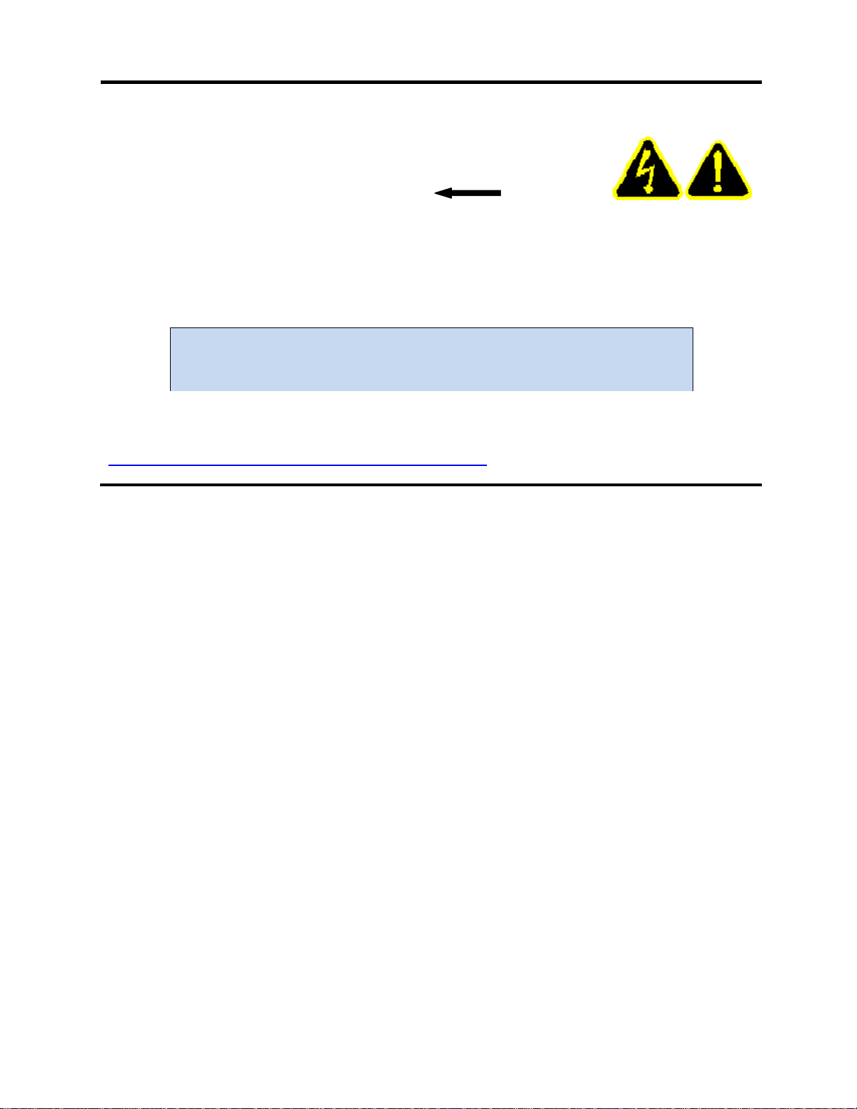
Assemble the CH+ System
1. Remove the Phillips-head screws that lock
the back cover plates on the base unit and
scanner boxes.
2. Pinch the latch tabs toward each other as
shown, and remove the back cover plates.
3. Stack the scanner box(es) on top of the base
unit.
Important: The base unit is not designed to support
the weight of more than 4 scanner boxes. For more
than 4 scanner boxes, we suggest you rack mount the
CH+ system. See Rack Mounting at the end of this
procedure.
Note: Each scanner box has two box-to-box cables
sitting inside the case.
Back
Cover Plate
Phillips
Screw
Latch Tabs
Max
4 Boxes
Box-To-Box Cables
Setting Up the CH+ Tester 5
4. Use box-to-box connectors to plug from the
base unit to the lower connectors of the first
scanner box.
5. If using more than one scanner box, connect
from the upper connectors of a lower box to
the lower connectors of an upper box.
6. Plug a power cord (notch side up) into each
box’s power connector.
7. Attach the back cover plates and screw in the
cover plate screws.
8. Set up the computer that will operate the
CH+.
CRT video monitors, florescent lights, and
equipment motors are electrically noisy devices
and should be kept at least 2 feet from the test
system (including the test fixturing and tested
device); otherwise measurement accuracy can
be compromised.
Note that LCD monitors (flat screens) do not emit
excessive noise and may be placed anywhere
convenient for the operator.
Lower Connectors
Power
Connector
notch up
Minimum
2 ft.(60cm)
From upper
connectors
of lower box
To lower
connectors
of upper
box
Setting Up the CH+ Tester 6
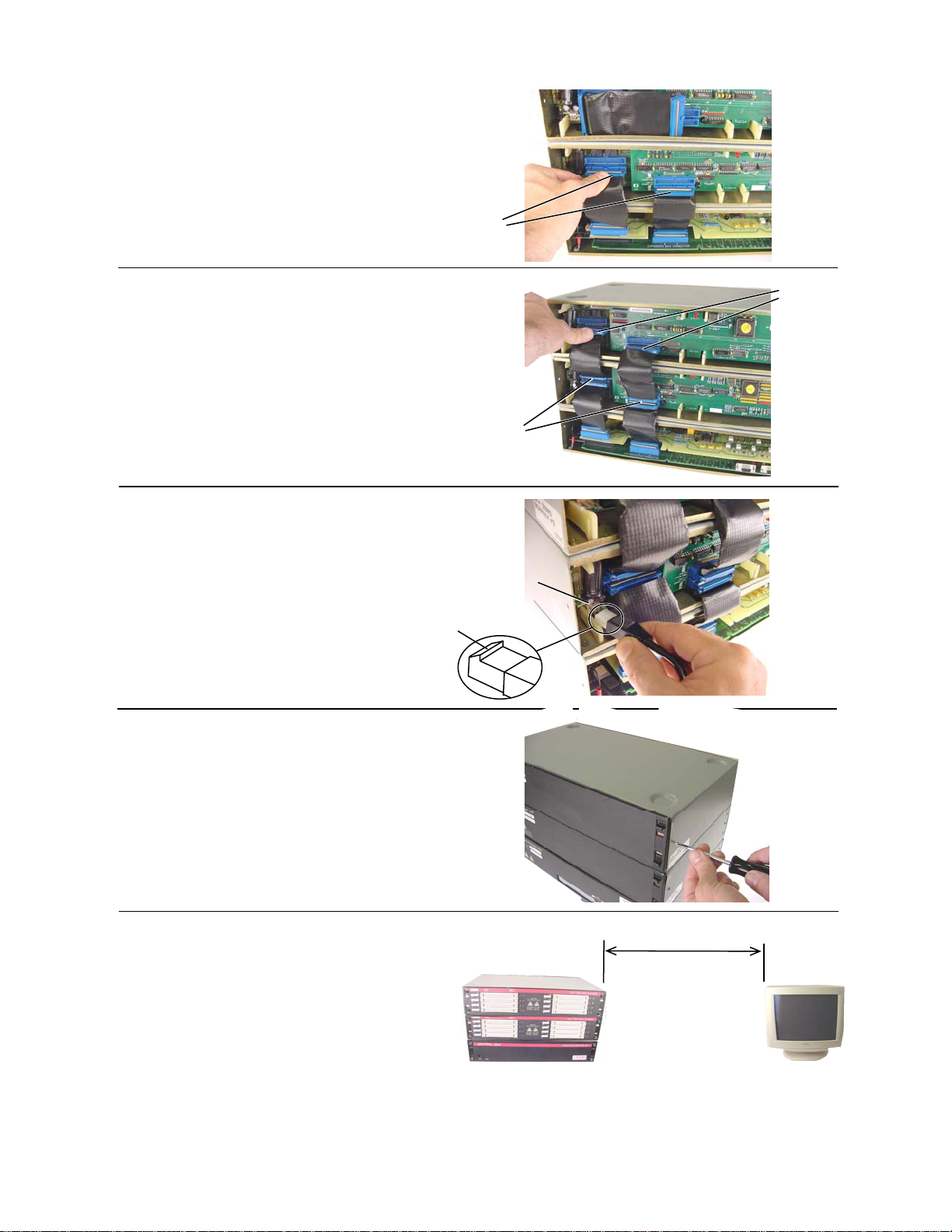
9. Connect one end of the 9-pin serial cable to
the port on the back of the base unit labeled
Serial Port to PC.
IF YOUR PC DOES NOT HAVE A SERIAL PORT…
Many new computers sold today do not include a
serial port as a default part of the standard
computer package.
Cirris Systems has recently qualified a USB port
to Serial port converter from Keyspan. You can
purchase this adapter direct from Cirris or from
many other sources commercially. If you choose
to purchase another make or model, we have
discovered that many other USB converters do
not work with our equipment. This adapter (out of
many that we have tried) has consistently
performed without any difficulties.
10. Connect the other end of the 9-pin serial
cable to a serial port on the back of your
computer.
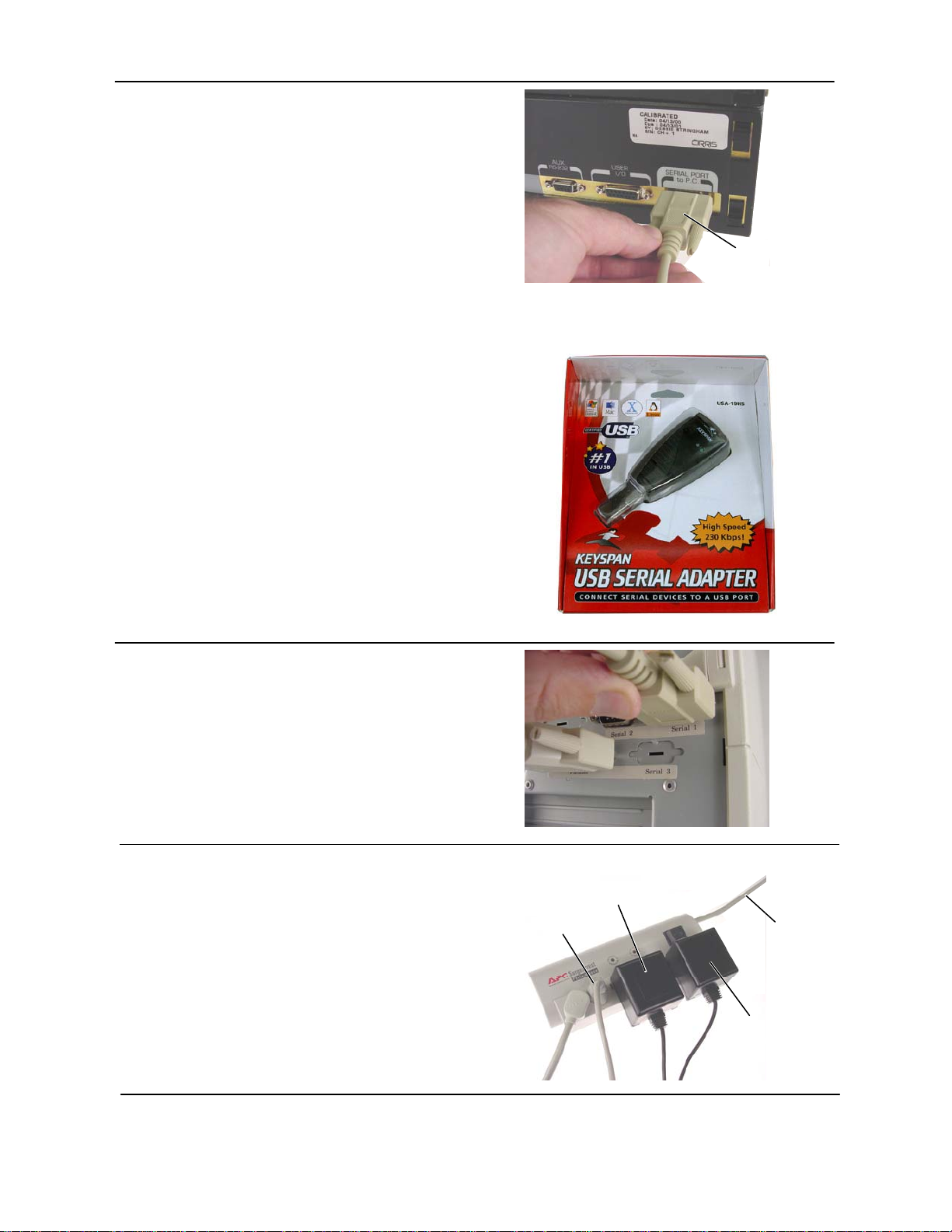
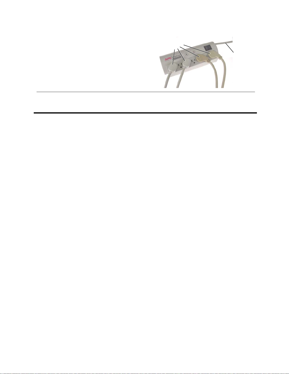
11. If possible, plug each wall transformer into
the same grounded plug strip as the
computer that will operate the system.
For optimum measurement accuracy, the CH+ must
have a consistent earth ground to the entire system.
Make sure to use grounded (3-prong) outlet strips and
plug them into a single outlet.
9-Pin Serial
Cable
To computer To grounded
wall outlet
To base unit
To scanner
box
Example:
Setting Up the CH+ Tester 7
If more than one outlet strip is needed for the system,
plug secondary outlet strips into a primary strip, and
then plug this strip into a grounded wall outlet.
You shouldn’t have to worry about overloading a single
outlet. Even a 5000 point CH system uses less than
500 watts of power.
If you are rack mounting the CH+ System, proceed to the following section. Otherwise skip to
Installing the easy-wire Software on page 9.
Example:
To secondary
plug strips
To grounded
wall outlet
Setting Up the CH+ Tester 8
Rack Mount the CH+ System
For a CH+ system with more than 4 scanner boxes, you must rack mount the CH+ system.
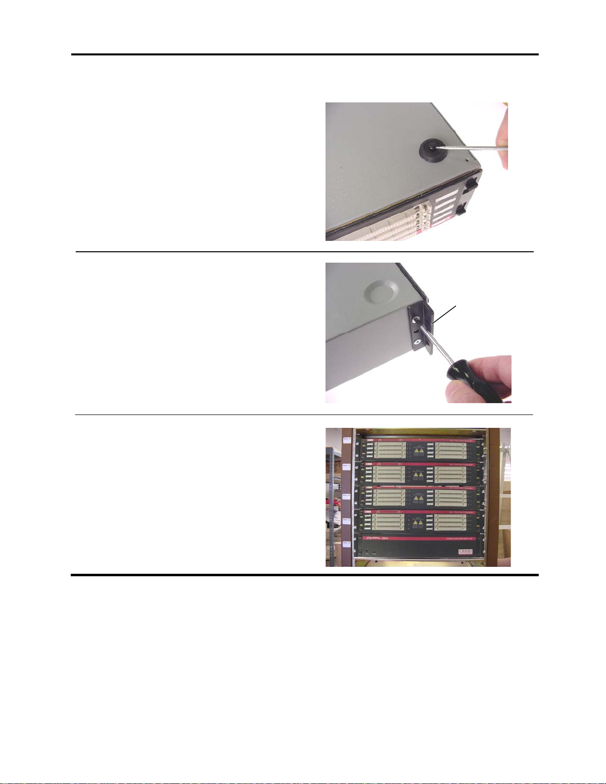
If you remove the feet of your CH+ system, you will be
able to remove each box separately from the rack.
1. Pry up the plastic plunger in the center of
each foot; then you can remove the foot.
2. Install the rack mounting brackets on the front
of each box.
3. Mount the boxes on top of each other in the
rack with the base unit on the bottom.
Cirris does not provide the screws to attach brackets to
the rack.
Continue with step 3 in the main assembly procedure.
rack mounting
bracket

Installing the easy-wire Software 9
Install the easy-wire Software
Before starting the Installation
Review the following for the appropriate installation.
Are you going to set up a stand-alone station, or a shared network installation?
On a Stand Alone Station
If you install the test database on a local station drive, only that workstation will access its
test database. If you want to use the same test information on other stations, you’ll have to
set up the tests on each station, or use floppy disks to export and import test information
between stations. To install the software only on a stand-alone station or stations, you will
only do the section below entitled Installing the easy-wire Software.
On a shared network
This is a nice way to make sure that all the stations on the production floor use the same
test information. To setup a network you must have a computer that meets the network
server requirements as specified on page 2.
If choosing to install on a network, note that there are now two ways to do this. Typically
you will want to choose the network only install. This newer network installation method
allows you to install both the easy-wire software and the easy-wire database together on
the network. All easy-wire stations load the same copy of easy-wire software and the
database from the network. This method greatly simplifies installing and updating the
easy-wire software. For this install do the section entitled Installing the Software only on
the Windows Server. Continue with the section entitled Completing a Network Only Install.
An older method to install easy-wire on a network has been to setup a network database
server. With this method you install only the easy-wire database on the server. The easy-
wire software is installed locally on each easy-wire station. If you use this method, when
installing a new easy-wire version you will have to update the network database and each
local easy-wire station. This method does allow you use the unreliable network option
when it is needed. In the event that you want to setup a network database server, first do
the section below entitled Installing the Software on each work station. Continue with the
section Installing a Network Database Server, and then Attaching a Station to a Network. .
Have you previously installed the software to do the demo?
If you’ve previously installed the easy-wire software for demo purposes, the test database
is installed on a local hard drive. Reinstalling the software from the Install CD will ensure
that you have the latest version of the software. If you’ve installed the easy-wire software
on a station and now want to do a network only install, call Cirris Technical Support for
assistance.
Installing the
easy-wire
Software

Installing the easy-wire Software 10
Installing the Software
1. Close all Windows applications on the computer.
2. Place the CD into the CD-ROM drive and wait. After a moment the CD should auto-load.
If the software does not auto-load, from the Windows taskbar, click Start, and then Run. Type: d:\install.exe (where
d: is the CD-ROM drive). Then click OK.
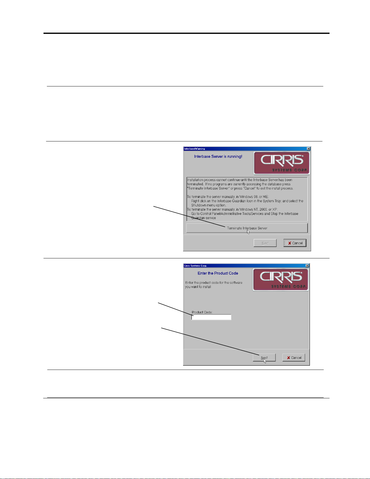
3. If this window appears, click on
Terminate Interbase Server.
If this window appears, the following
window should say that the Interbase
Server was successfully terminated.
Click Next to continue.
4. Enter easy-wire for the product code.
Then, click Next.
5. Click Next to confirm a Single User Station installation. Click Next after reading the license
agreement and the release notes.
easy-wire

Installing the easy-wire Software 11
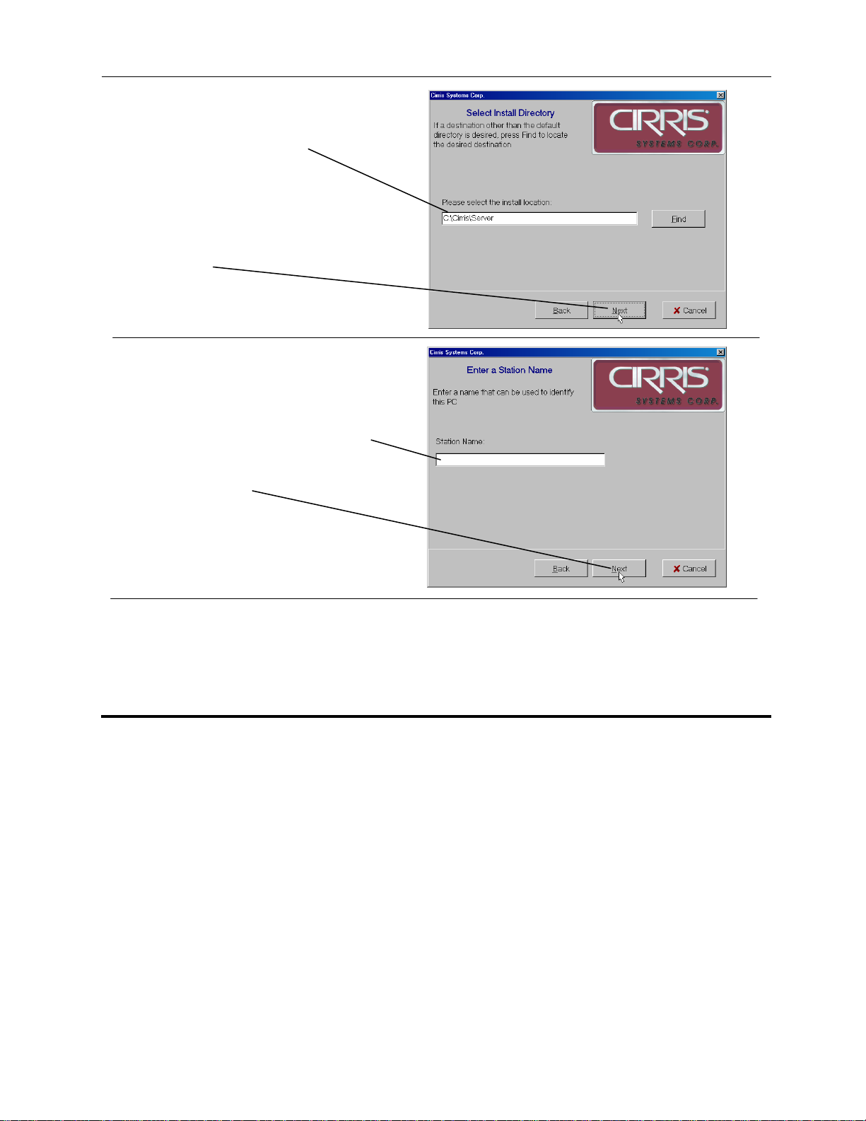
The default install location will be displayed
here.
Do not change the default install location
unless there is a specific reason to do so as it
may cause problems in the future.
6. Click Next.
7. Select Signature CH+ for the type of
tester that will be attached to this
station.
Then click Next.
8. Enter a name that can be used to
identify this station or server.
Note: If this is a station or network database
installation, the station name entered here will
be used on reports generated by this station.
If needed you can change the station name at
a later time (see Station ID or Station Name in
the help system).
Then click Next.
9. After the installation is complete, click Finish.
If you are installing a stand-alone station, you have completed the installation and can skip to
Checking the System on page 16. Otherwise complete the appropriate following sections to
complete a network installation.
C:\Cirris\EasyWire\
9

Installing the easy-wire Software 12
Completing a Network Only Install
On the server where the easy-wire software has been installed, share and set user rights for the
Cirris folder. The following steps describe this process.
1. Open Windows File Explorer. You can do this by right clicking on Start and selecting
Explore.
2. Using Windows File Explorer expand the Program Files folder on the root drive.
3. In the Program Files folder find the folder named Cirris. Right Click on Cirris, and select
Sharing and Security in the pop up menu.
4. In the Cirris Properties dialog box, select the Sharing tab. Select the option Share this
folder.
5. Click the Permissions button. In the Allow column make sure that at least the check boxes
for Change and Read Control are checked for each user group that will access the easy-
wire software.
At each station, create icons for the easy-wire application and help system. The following steps
describe the process to create the icons:
1. Using Windows File Explorer browse to the EasyWire folder under the Cirris folder you
shared in the previous steps.
2. Right click on easy-wire.exe. From the pop up menu select Create Shortcut. A shortcut
called Shortcut to easywire will be created in the folder.
3. Drag Shortcut to easywire to the desktop.
4. Using Windows File Explorer browse to the Help folder under the Cirris folder.
5. Right click on CirrisHelp.htm. From the pop up menu select Create Shortcut. A shortcut
called Shortcut to CirrisHelp will be created in the folder. Drag this shortcut to the desktop
as well.
6. On the desktop rename Shortcut to easywire and Shortcut to CirrisHelp to simply
easy-wire and easy-wire help respectively. Renaming is done by slow clicking on the
shortcut name field. (i.e. Click once to select the name field, after at least one second, click
again on the name field). When the name changes to editable text, change it to the new
name.
At each station, test the newly created icons and complete the station configuration by doing the
following steps.
1. Double click on the newly created easy-wire icon. When the easy-wire software is run for
the first time, you will be prompted to select the type of testers used at the station and the
line voltage frequency.
2. Make sure that the easy-wire software correctly accesses the server database.
A random number is initially assigned for the station name. The station name will be
recorded with test data used for reporting. You can change this number to a representative
name such as Station 1.
3. To change the station name, from the easy-wire main menu, click Utilities, Setup System
Options, Station Name Tab, and edit the Station Name field.
Installing the easy-wire Software 13
Setting up a Network Database Server
Check that the Computer is capable:
The computer that runs the network database should be dedicated to running the database
software, and must meet the other system requirements listed at the beginning of this guide.
The network database server should not be used as a workstation.
Install the Software on the database server:
1. Close all Windows applications on the computer.
2. Place the CD into the CD-ROM drive and wait. After a moment the CD should auto-load.
If the software does not auto-load, from the Windows taskbar, click on Start, then on Run. Type: d:\install.exe
(where d: is the CD-ROM drive). Then click OK.
3. If this window appears, click Terminate
Interbase Server.
Note that the Cancel button can be pressed at
any time to terminate the install process.
4. Enter the Product Code for the Network
Database Server included on the
software CD case.
After entering the product code, click
Next.
5. Click Next to confirm a Network Database Server installation. Also click Next after reading
the license agreement and release notes
Installing the easy-wire Software 14
6. The default install location will be
displayed here.
Do not change the default install
location unless there is a specific
reason to do so as it may cause
problems in the future.
7. Click Next.
8. Enter a name that can be used to
identify this server.
Then click Next.
9. After the installation is complete, click Finish.
Before proceeding to the next section, check that the folder c:\Cirris\Server\Database on the
network server is shared. You can check the folder is shared by opening Windows Explorer on
the server. Right click on c:\Cirris\Server\Database. In the displayed pop down menu, click
Sharing. In the properties box make sure the option Share this folder is checked.
Installing the easy-wire Software 15
Attaching a Station to the Network Database Server
You must do the following procedure at each station computer (not at the network database
server). Before performing this process you should have previously installed the software on
the Network Database Server.
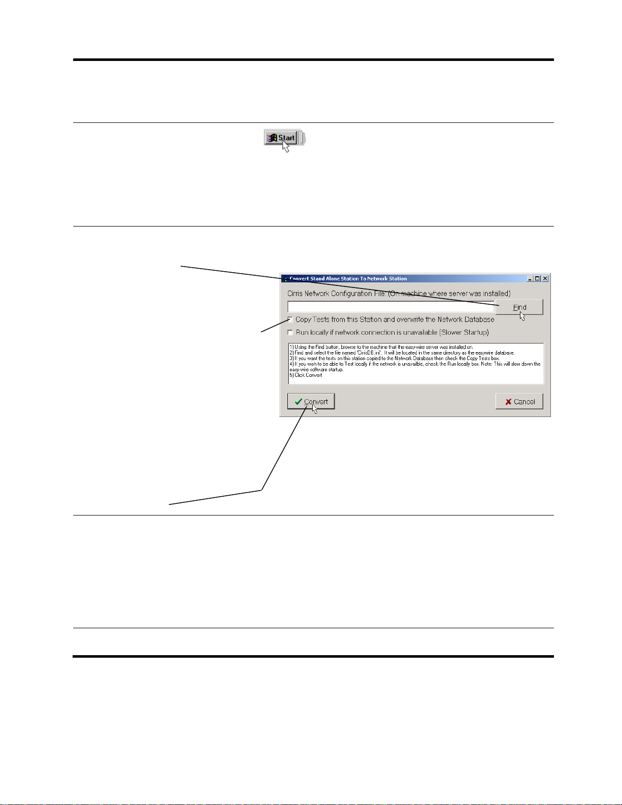
1. Click the Windows Start button.
2. Click Programs.
3. If attaching an easy-wire station, move the
mouse to Easywire and click Attach Station to
Network.
4. When this window appears, use
Find to locate the network
configuration file.
This file will be located on the Network
Database Server in the
C:\Cirris\Server\Database directory.
5. If you previously created tests on
stand alone stations, you can copy
the test programs from one stand
alone station to the network
database. Check this box only if
this situation applies to you and if
the test programs you want to copy
to the network database are on
this station.
Note: Test programs from other stand
alone stations must be exported, and
afterwards imported at a station connected
to the network database.
6. Click Convert.
If installing easy-wire software, the conversion
process may take anywhere from a few minutes
to several hours depending on how much data is
being converted to the network database.
After the conversion process completes, you
should see a Conversion Complete Window.
The station is ready for use.
Proceed to the next section, Checking the System.

Checking the System 16
Starting the Software and Checking the System
The easy-wire software icon
should be on the desktop. You
will also find an easy-wire folder in
the programs menu.
1. Double-click on the
easy-wire icon.
If you don’t see the icon on the desktop you can run
the program from the task bar. Click Start button,
select programs, easy-wire Software, then click easy-
wire.
The User Login screen appears.
Unless this is a network station
where password security has
previously been setup, the default
is no password.
2. Click on OK.
Passwords can be set up to
identify users and prevent
unauthorized changes.
3. Click OK to all Hardware
Status Updates.
After the first time you
load the software, the
Hardware Status
Update screens
should not reappear
unless the system
has changed.
4. Check that the status
indicator is green.
If the indicator is green,
Go to step 5.
If red, see the next heading:
Troubleshooting a Red
Status Indicator.
A green status LED
indicates the tester is
working.
Checking
the System

Checking the System 17
5. Click on the green status
indicator. You should hear
a tone.
If you hear the tone,
proceed to the last section:
Find Information to Use the
CH+.
If not, on the next page see
If System Sound is Not
Working.
For any other unresolved
problems, see Startup and
Verify in the help system, or
call Cirris Technical Support
at 1-800-441-9910.
It is imperative that
sound is working on
the test computer.
The easy-wire
software relies
heavily on sound
prompts to provide
feedback to the
operator.
Troubleshooting a Red Status Indicator
If you have a red status indicator in the easy-wire main menu, check that:
1. A powered wall transformer is plugged into
each box.
2. The serial cable is connected from the
serial port of the computer to the serial port
on the base unit of the tester.
If power and serial cable are correctly connected, you can check your computer’s serial port
using the loop back plug provided. For assistance, call Cirris Systems Technical Support at
1-800-441-9910.
serial cable

Checking the System 18
If System Sound is Not Working
If system sound is not working or is not sufficiently loud, check that:
1. Speakers are connected to the PC, and if
required, plugged into a power outlet.
2. Speakers are turned on and the volume turned up.
3. The Windows sound mute box is not checked, and
the volume is adjusted.
Note: To access the Windows sound control, click on the
speaker symbol in the bottom right corner of the Windows
screen.
If none of these things remedies your computer’s sound problems, you should use a different
computer, or seek further help from where you purchased your computer. System sound is
critical for proper operation of the easy-wire software.
Mute box Speaker
Symbol
Volume

General Information 19
Maintenance
Tester Maintenance
The CH+ tester requires no maintenance. If desired you may clean the outside surfaces of
the CH+ tester. Since some cleaning agents leave a conductive residue, take special care to
not allow the cleaning agents to come into contact with the test point connectors or the
circuitry inside the casework.
Fixture Maintenance
The contacts on the fixturing that mate to the device under test may wear due to repeated
insertion cycles. Contact wear can result in higher connection resistances which in turn will
increase the measured resistances for the tested device. For this reason Cirris recommends
that customers evaluate the number of mating cycles and the cycle life of fixture contacts to
determine maintenance intervals for testing and/or replacing fixturing contacts. A good way
to check fixture contact resistance is to construct and use a shorting block. For more
information on creating shorting blocks, see http://www.cirris.com/adapters/test-adapt.html.
Service
All Cirris Testers are designed as modules for easy servicing. Should your Cirris tester
require service, as directed by Cirris support personnel, you may need to send the affected
module or the entire tester back to Cirris for repair. If needed during the repair period, a
loaner tester can be sent to you. You should not attempt to service any circuit board at the
component level. All component-level service should be performed by Cirris technicians.
Calibration
With your CH+ tester you should have received a Certificate of Calibration. Before leaving
the factory every CH2 tester is calibrated in compliance with ANSI/NCSL Z540-1-1994 and
MIL-STD-45662A to standards traceable to the NIST in the United States. The tester should
thereafter be calibrated annually.
To verify calibration and functionality, you can purchase the CH+ Performance Check Kit.
The CH+ Performance Check kit has a valid calibration period of 5 years after which it must
be replaced. In addition to the performance check kit, you need a calibrated volt meter and
high voltage probe capable of measuring up to 1500 VDC. Note that in the event a Cirris
tester is found to be out of calibration there are no adjustable controls; the tester, or the
affected portions of the tester, must be sent back to a Cirris facility for repair.
General
Information

General Information 20
Tester Symbols
The symbols on the outside of the tester are explained as follows:
!
Caution: See
manual for more
Information
Risk of
shock
When performing a high voltage test the CH+ tester limits
the applied current to 1.5 milliamps and the applied charge
to 45 micro coulombs. These electrical levels are
considered safe for adults; however, some people could be
affected adversely even at these levels. For this reason
avoid touching the high voltage. Whenever possible using a
DC voltage for high voltage testing provides an added level
of operator safety.
Conditions for Operation
Your CH+ Tester is intended to be used indoors at a temperature of 10 to 40 degrees
Celsius. Best performance can be obtained at a relative humidity less than 70%. Insulation
Resistance Measurements will degrade over 70% relative humidity. The unit can be
mounted in a ventilated compartment. Be sure not to block the vents on the sides and back
of the tester.
Never apply live voltages to the test points or probe input of your Cirris tester. Power
supplies and other accessories not approved by Cirris may cause damage or present a
hazard. If you use a Cirris product in a manner not specified in this manual and the
accompanying help system, the protection provided by the product may be impaired.
Table of contents
Other Cirris Test Equipment manuals

Cirris
Cirris CH2 User manual

Cirris
Cirris easy-wire CR User manual

Cirris
Cirris CH2 User manual

Cirris
Cirris Touch1 LV Installation and operation manual

Cirris
Cirris CH2 User manual

Cirris
Cirris CH2 User manual

Cirris
Cirris Easy-Touch Pro User manual

Cirris
Cirris Touch 1 User manual

Cirris
Cirris Easy-Touch Pro User manual

Cirris
Cirris CH2 User manual

Cirris
Cirris 4200 Series User manual

Cirris
Cirris 4200 Series User manual

Cirris
Cirris 4200 Series User manual

Cirris
Cirris CR User manual

Cirris
Cirris CR User manual

Cirris
Cirris 4200 Series User manual

Cirris
Cirris CH2 User manual

Cirris
Cirris signature 1100R+ User manual

Cirris
Cirris Touch1 LV Installation and operation manual

Cirris
Cirris CR User manual


