Cirris CH2 User manual

Cirris CH2
User Manual

Table of Contents
THE CH2 TESTER .................................................................................................................... 1
INTRODUCTION ..............................................................................................................................................................1
PARTS LIST ....................................................................................................................................................................1
ADD-ON SCANNER PARTS LIST ..........................................................................................................................................2
GENERAL INFORMATION ....................................................................................................... 3
MAINTENANCE...............................................................................................................................................................3
TESTER SYMBOLS............................................................................................................................................................4
CONDITIONS FOR OPERATION ...........................................................................................................................................4
HELP...................................................................................................................................... 5
ACCESSING THE ONLINE MANUAL/HELP SYSTEM ..................................................................................................................5
SOFTWARE INSTALLATION GUIDE .......................................................................................... 7
REQUIREMENTS FOR A STATION OR NETWORK SERVER...........................................................................................................7
INSTALLING EASY-WIRE SOFTWARE AND CIRRIS SERVER SOFTWARE .........................................................................................7
STARTING THE SOFTWARE ................................................................................................................................................8
UPDATING THE SERVER CONFIGURATION.............................................................................................................................8
(1100) EASY-WIRE PC CONTROL FOR BENCHTOP TESTERS ....................................................................................................8
(CR, CH2) ATTACHING TO A NETWORK DATABASE SERVER ....................................................................................................8
SETTING UP THE TESTER ........................................................................................................ 9
INSTALLING ADD-ON SCANNERS ........................................................................................................................................9
ELECTRICAL ASSEMBLY...................................................................................................................................................10
CHECKING THE SYSTEM ....................................................................................................... 12
TROUBLESHOOTING A RED STATUS INDICATOR ...................................................................................................................14
CHECKING THE SOUND...................................................................................................................................................15
CONNECTING TO A NETWORK ............................................................................................. 17
ATTACHING A STATION TO THE NETWORK DATABASE SERVER................................................................................................18
ADDING OR REMOVING SCANNER MODULES....................................................................... 21
TRADITIONAL FIXTURING..................................................................................................... 26
BUILDING TRADITIONAL FIXTURING ..................................................................................................................................26
TWO-WIRE FIXTURING...................................................................................................................................................26
BUILDING FIXTURING FOR FAST ATTACH............................................................................................................................27
FOUR-WIRE FIXTURING ..................................................................................................................................................29
XHV POWER SUPPLY............................................................................................................ 32
INTRODUCTION ............................................................................................................................................................32
BEFORE YOU BEGIN.......................................................................................................................................................32
PARTS LIST ..................................................................................................................................................................32
YOU MAY HAVE RECEIVED .............................................................................................................................................32
BUILDING AN HV INTERLOCK ..........................................................................................................................................33
SET UP.......................................................................................................................................................................35
HIGH VOLTAGE TEST PARAMETERS ..................................................................................................................................38

CUSTOM INSTRUCTIONS...................................................................................................... 39
INTRODUCTION ............................................................................................................................................................39
CATEGORY OVERVIEW ...................................................................................................................................................40
CATEGORY DESCRIPTIONS...............................................................................................................................................41
EXTERNAL INSTRUMENTS .................................................................................................... 43
REQUIRED PARTS FOR MEASURING DEVICES ......................................................................................................................44
ATTACHING EXTERNAL INSTRUMENTS ...............................................................................................................................44
SET UP.......................................................................................................................................................................45
ENERGIZATION BOX............................................................................................................. 50
INTRODUCTION ............................................................................................................................................................50
SELECTING A POWER SUPPLY ..........................................................................................................................................50
REQUIRED PARTS..........................................................................................................................................................51
SET UP.......................................................................................................................................................................51
EBOX INSTRUCTIONS .....................................................................................................................................................53
ENERGIZATION BOX PERFORMANCE VERIFICATION ..............................................................................................................57
ITEMS NEEDED FOR THE PERFORMANCE VERIFICATION TEST..................................................................................................57
SELECTING POWER RESISTORS.........................................................................................................................................57
WARRANTY ......................................................................................................................... 52

Error! Reference source not found. 1
THE CH2 TESTER
Introduction
Use this guide to install Cirris Easy-Wire™software, setup the CH2 tester, connect the CH2
tester to a network, get an overview of the test system, and set up CH2 expandability features.
If you need assistance at any time, call your Cirris Customer Support representative. In the
U.S.A. Cirris Sales and Customer Support may be reached at 1-800-441-9910.
Hipot Warning!
Possible electric shock!
Cirris hipot testers are designed to be safe for operators. Injuries from hipot test
equipment are rare. Still, not every hipot test situation is safe. Hipot testing
does not present a danger to healthy individuals; however, occasional mild
electric shock may be experienced. Small shocks only occur during a hipot test
when the operator touches an energized connection point. Any shock from the
tester may result in a hipot test failure.
Medical Warning!
A child or individual wearing a cardiac pacemaker, an insulin pump, or any
electronically controlled medical device should NOT perform hipot testing.
For ideas on improving hipot safety visit:
www.cirris.com/testing/guidelines/hipot_safety.html
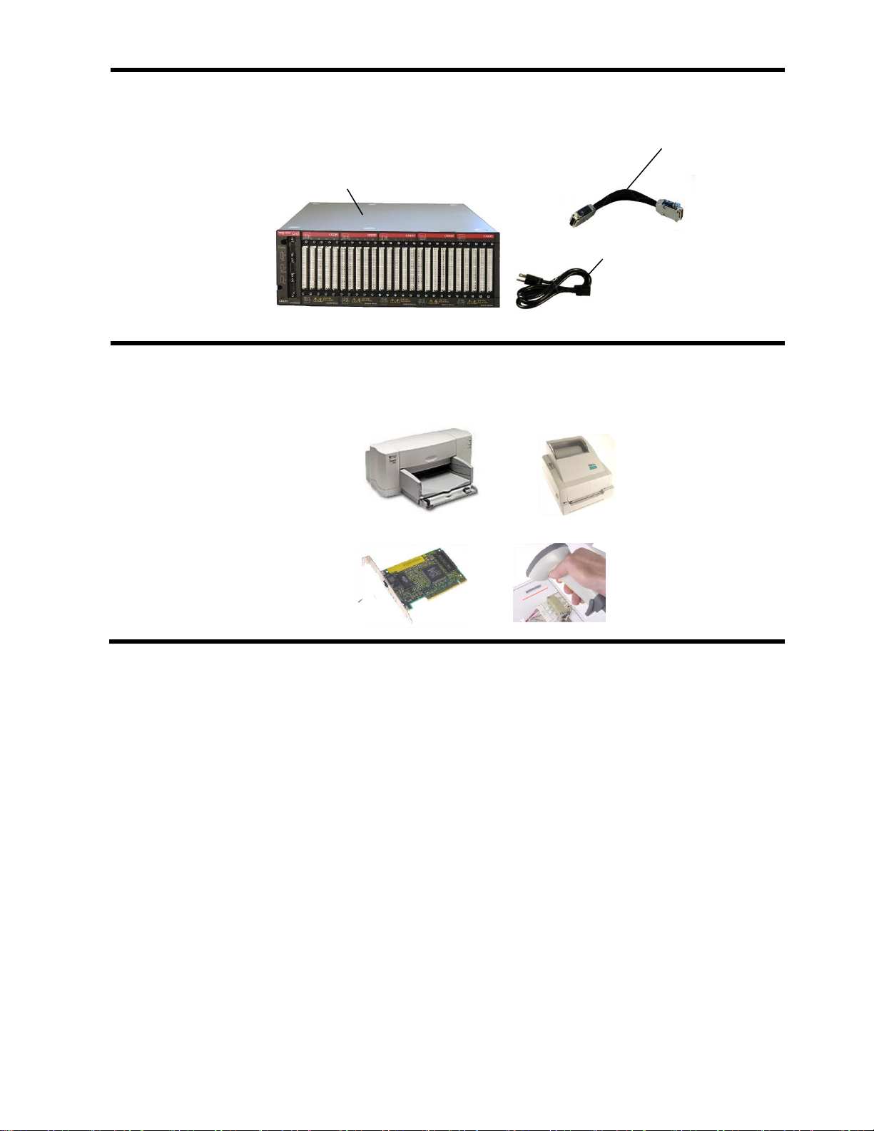
Parts List
Each CH2 order comes with the following parts:
CR Tester
Base Unit
One required per system.
Provides up to 800 points
in 160 point increments.
Hand Held Probe
CR Tester
easy-wire Software USB
flash drive
USB Cable
Power Cable
HV Interlock
Override
Error! Reference source not found. 2
Add-on Scanner Parts List
A CH2 add-on scanner system is optional and includes the following parts:
You may want to add these optional accessories
You can purchase the listed accessories at computer and office supply stores. Each accessory
is easy to integrate with your computer and CH2 test system to fit your requirements.
Add-on Scanner Chassis
Provides up to 800 points in
160 point increments.
Box-to-Box Cable
One for every Scanner
Chassis.
Power Cable
Varies according to
the country of receipt.
Sheet Printer
For printing test reports
and fixturing information
Label Printer
For printing labels to
apply to the device-
under-test
PC Network Card
For sharing test
information between
CH2 testers (requires
purchase of easy-wire
networking software)
Barcode Scanner
For replacing the mouse
on the production floor

Error! Reference source not found. 3
GENERAL INFORMATION
Maintenance
Tester Maintenance
The CH2 tester requires no maintenance. If desired you may clean the outside surfaces of the
CH2 tester. Since some cleaning agents leave a conductive residue, take special care to not
allow the cleaning agents to come into contact with the test point connectors or the circuitry
inside the casework.
Fixture Maintenance
The fixturing contacts that mate to the device-under-test may wear due to repeated insertion
cycles. Contact wear can result in higher connection resistances which increases the
measured resistances for the device-under-test. For this reason Cirris recommends that
customers evaluate the number of mating cycles and the cycle life of fixture contacts to
determine maintenance intervals for testing and/or replacing fixturing contacts. A good way to
check fixture contact resistance is to construct and use a shorting block. For more information
on creating shorting blocks, see http://www.cirris.com/adapters/test-adapt.html.
Service
Cirris Testers are modular in design for easy servicing. If your Cirris tester requires service, as
directed by Cirris support personnel, you may need to send the affected module or the entire
tester back to Cirris for repair. If needed during the repair period, a loaner tester can be sent
to you. You should not attempt to service any circuit board at the component level. All
component-level service should be performed by Cirris technicians.
Calibration
With your CH2 tester you should have received a Certificate of Verification. Before leaving the
factory every CH2 tester is calibrated in compliance with ANSI/NCSL Z540-1-1994 and MIL-
STD-45662A to standards traceable to the NIST in the United States. The calibration of the
tester should thereafter be verified annually.
To verify calibration and functionality, you can purchase the CH2 Performance Check Kit. In
addition to the performance check kit, you need a calibrated volt meter and high voltage probe
capable of measuring up to 1500 VDC.
Note: In the event a Cirris tester is found to be out of calibration, there are no adjustable
controls; the tester, or the affected portions of the tester, must be sent back to a Cirris facility
for repair.

Error! Reference source not found. 4
Tester Symbols
The yellow lightning bolt symbols on the CH2 tester inform operators that high voltage is
involved with the scanner modules and that there is risk of electric shock. The yellow
exclamation mark means to use caution and see the manual for more information. See more
details below.
Caution: See
manual for more
Information
Risk of shock
When performing a high voltage test, the CH2 tester
limits the Total Current to 2.5 milliamps and the applied
charge to 45 micro coulombs. These electrical levels
are considered safe for adults; however, some people
could be adversely affected even at these levels. If
you are using an xHV supply, the applied current limit
is 22 milliamps. For these reasons, Cirris recommends
that you keep the Real Current setting as low as
possible (1 milliamp or smaller), and avoid touching the
cable during the hipot test. Using a DC voltage for
high voltage testing also provides an added level of
operator safety. See the Cirris website for more hipot
safety information.
See manual for more
Information
The symbols with a white exclamation mark on the back
of the tester, inform operators that more information
about the Digital I/O, Auxiliary HV input, and Auxiliary
Input Supply Connections can be found in the CH2
User Manual and in the Easy-Wire on-line manual/help
system.
The Digital I/O Connector allows the tester to respond
to inputs and create outputs without the use of a PLC.
Easy-Wire software version 8.80 or higher has Digital
I/O capability. See the Easy-Wire help system for more
information.
The Auxiliary HV Input and Auxiliary Supply
Connections are for non-standard features. You can
call Cirris for more information on the intended function
of these features.
Conditions for Operation
Your CH2 Tester is intended to be used indoors at a temperature of 50 to 104 degrees
Fahrenheit (10 to 40 degrees Celsius). Best performance can be obtained at a relative
humidity less than 70%. Insulation Resistance Measurements will degrade at over 70%
relative humidity. The unit can be mounted in a ventilated compartment. Be sure not to block
the vents on the sides and back of the tester.
Never apply live voltages to the test points or probe input of your Cirris tester. Power supplies
and other accessories not approved by Cirris may cause damage or present a hazard. If you
use a Cirris product in a manner not specified in this manual and the accompanying help
system, the protection provided by the product may be impaired.
Help 5
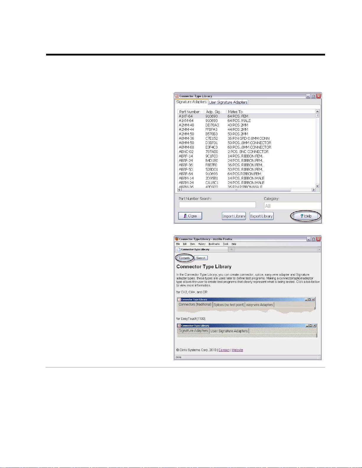
HELP
Accessing the Online Manual/Help System
In addition to this user manual, the complete Easy-Wire manual is available in the Easy-Wire
help system. Sections of the online manual may be printed if desired.
1. In the Easy-Wire software, click
the Help button at the bottom of
any window.
The help information for that
window will appear on the screen.
2. To view the entire online manual
by chapter, click Contents.
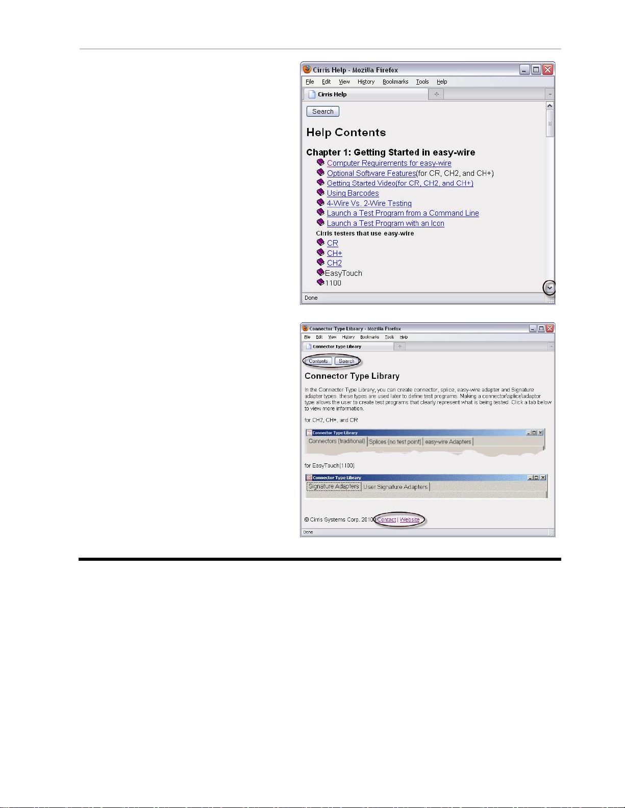
Help 6
3. Click any link to view the help for
that specific topic. Scroll down if
necessary.
In every Help page, you can do the
following:
•Click Contents to view the
Easy-Wire manual by chapter.
•Click Search to find information
using key words.
•Click Contact to view the contact
information for Cirris.
•Click Website to view the Cirris
website if you have an internet
connection.

Software Installation Guide 7
SOFTWARE INSTALLATION GUIDE
Requirements for a Station or Network Server
•2.0 GHz min. processor speed
•Windows 7® or later
•15 GB hard drive space
•4 GB RAM
•256 MB min. video memory
•1024 x 768 min display resolution
•Sound (for audible feedback)
•USB 2.0 or 3.0 port
•Internet connection: Not required, but if available, can facilitate support issues.
For assistance:
•Call Cirris toll-free at 1-800-441-9910 or email [email protected]om.
•Outside the US, contact the Cirris office nearest you.
Updating a Previous Installation
IMPORTANT! Back up your database before you update your Cirris software installation.
Depending on the software version that is currently installed, you may need to perform special
steps before installing the current version.
•If your previously installed software version is older than 2008.2.0, you must remove the previous
version and store its data files before you install the new version.
•If your previously installed software version is 2008.2.0 or newer, proceed with the instructions
below.
Note: If you are unsure of the previously installed version number, start your Easy-Wire software
and check the version information (located on the right side of the Easy-Wire main menu) before
proceeding.
Installing Easy-Wire Software and Cirris Server Software
There may be driver conflicts between your tester and Windows. We therefore advise you to
install the software before attaching the tester.
1. Install Cirris Server Software on the server by downloading Cirris Server Software
from cirrris.com and following the installation steps as they appear on screen. This will
allow networking on all Easy-Wire stations.
2. Install Easy-Wire on each of the client PCs in the same manner by downloading Easy-
Wire from cirris.com and following the installation steps as they appear on screen.
During the software install, the drivers will automatically load to your machine. If the installation is aborted
or fails, you can install the drivers manually. The driver needed to run the USB testers is called
Silicon_Labs_Driver. The current version can be found under C:\Program Files
(x86)\Cirris\Easywire\Silicon_Labs_Driver.

Software Installation Guide 8
Starting the Software
1. Double-click the Easy-Wire software icon to start the software.
2. Make sure you select the appropriate tester type in the User Login window.
Note: If you’ve updated an existing installation, the user name and password will be the same.
3. The main menu will display. If you have updated an existing installation, the software
should allow you to access your previous data.
Updating the Server Configuration
Share the Cirris folder with those who have read/write permissions. Default folder location:
C:\Users\Public\Public Documents\Cirris.
(1100) Easy-Wire PC Control for Benchtop Testers
If you purchased your 1100 tester with Easy-Wire software, your tester will already be enabled to
interface with your PC.
If you purchased your 1100 tester without Easy-Wire and have since purchased the PC Control
feature, follow these steps:
1. Install the Easy-Wire software on a PC.
2. Connect your tester to the PC.
3. Launch Easy-Wire Software. In the Easy-Wire main menu, click Utilities, Setup System
Options, Enable Features.
4. Follow the prompts in the “Features Available on this Tester” window.
a. Contact Cirris and provide the given serial number.
b. Enter the Feature Key that Cirris will have provided to you.
Press Install the Feature.
(CR, CH2) Attaching to a Network Database Server
1. On each station that will be attached to your network, click the Windows Start button.
2. Click on All Programs, Cirris Systems Corporation, [Installed Software], Attach Station to
Network.
3. When the “Convert Stand Alone Station to Network Server” window appears, click Find
Server Location to locate the database configuration file. This file will be located on the
Network Database Server with the following default path:
C:\Users\Public\Documents\Cirris\common\CirrisDataAccessServer.ini.
4. Click Convert.
Setting Up the CH2 Tester 9
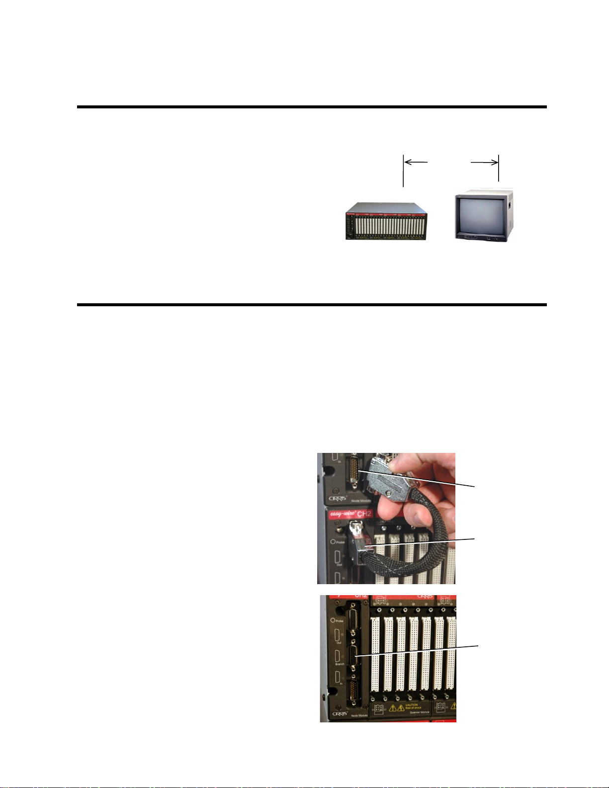
Setting Up the Tester
Before setting up the tester, select a test area where you can keep 2 feet (60 cm) between the
test system and noise emitting electronics.
Some examples of electrically noisy
devices include:
•CRT video monitors
•Florescent lights
•Equipment motors
Keep such devices at least 2 feet from the
test system, test fixturing, and
device-under-test. Otherwise, measurement
accuracy may be compromised.
•
Installing Add-on Scanners
Close together: Stacking the add-on scanners onto the base unit is the standard configuration. The
system is less susceptible to electrical noise in the environment, and therefore generally more accurate.
This configuration supports the supplied box-to box cable(s).
Spaced apart: The units can be spaced apart to allow for a shorter interface cable to the device-under-
test. For this type of configuration you must order custom box-to-box cables from Cirris. The maximum
total length of a box-to-box cable is 200 ft (60m).
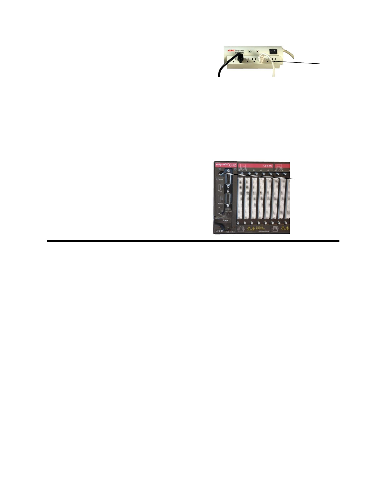
1. Connect the box-to-box cable from
the OUT connector on the base unit
to the IN connector on the next unit.
You may also connect a box-to-box cable
from a BRANCH connector to the IN
connector of another unit.
Minimum
2 ft.(60cm)
OUT
Connector
IN
Connector
BRANCH
Connector

Setting Up the CH2 Tester 10
2. Plug the power cord into the additional scanner. A power connection is needed for each
scanner chassis.
Electrical Assembly
1. Insert one end of the USB cable into the USB
port on the back of the Base Unit. Insert the
other end into a USB port on your computer.
Note: For more reliable tester operation, connect the tester’s USB port directly to the PC’s
USB connect and not a USB Hub.
2. Connect the HV Interlock Override to the
Digital I/O Connector on the Base Unit.
Note: CH2 testers made after March of 2007, have HV interlock capability. An interlock helps
protect operators from high voltage during the high voltage test. For more information on
interlocks, search the word “interlock” in the Easy-Wire help system.
3. Plug the power cord into the Base Unit’s power
connector. Make sure the back panel power
switch is in the ON position.
Power switch
(not found on
every tester)
Digital I/O
connector
Power
connector
USB port
Setting Up the CH2 Tester 11
4. Plug the other end of the power cord into the
same grounded outlet or plug strip that is used
for the computer. IF your tester has a power
switch on the back panel, make sure it is in the
ON position.
The power supply auto adjusts to line voltages
of either 120 VAC 60 hertz or 240 VAC 50
hertz.
For optimum measurement accuracy, the CH2
must have a consistent earth ground to the
entire system. Make sure to use a grounded
(3-prong) outlet or plug strip.
5. On the front of the tester, insert the probe into
the probe port. Probes can be plugged into any
or all testers in a multi-tester system.
Probe port
Grounded
outlet
Checking the System 12
CHECKING THE SYSTEM
The tester goes through a series of self tests upon boot up. These tests check to ensure that
the hardware and software are working properly. In the Easy-Wire main menu, you can tell if
the tests pass or fail by checking the status indicator. You can also check the sound from the
Easy-Wire main menu.
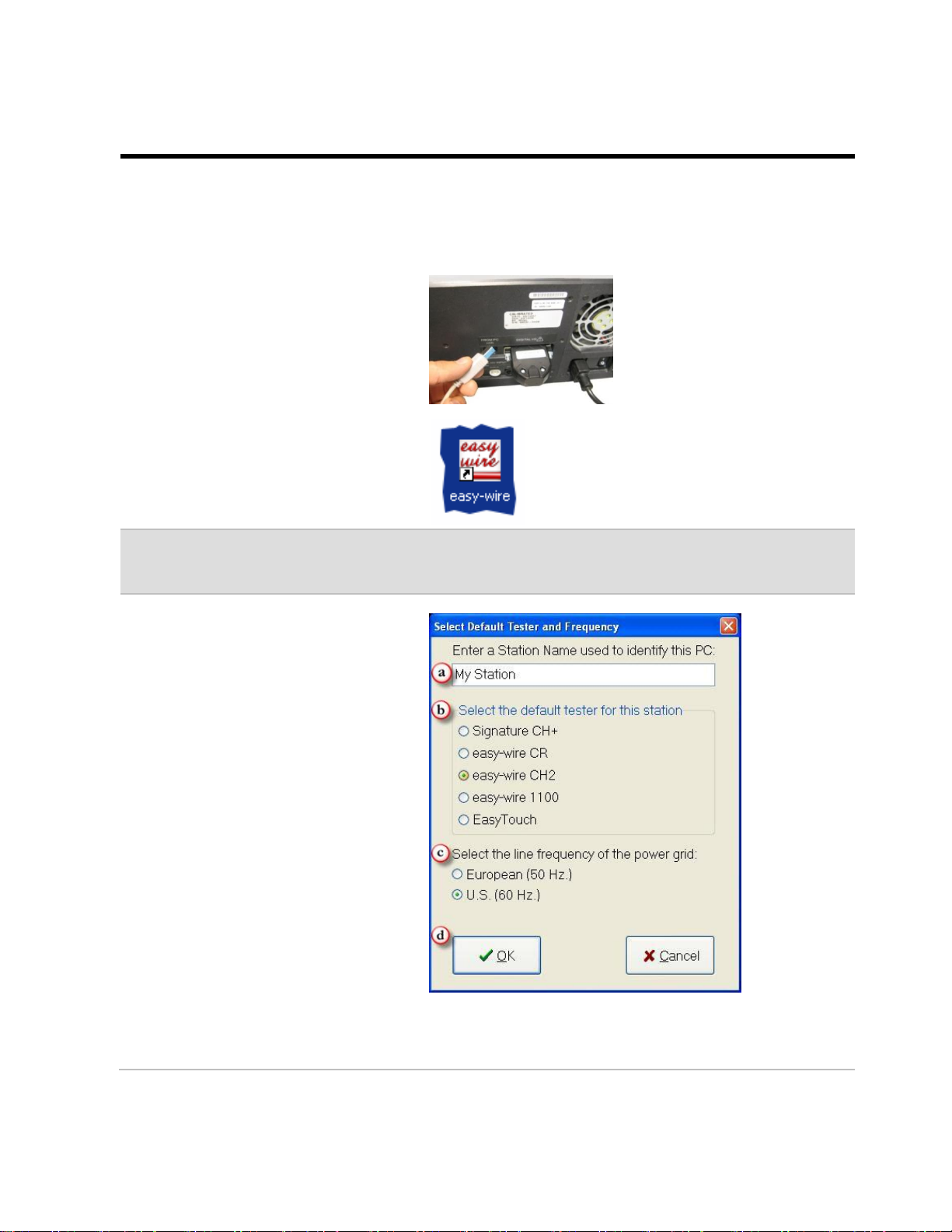
If you disconnected the USB cable
while updating the software,
reconnect it.
1. On your desktop, double-click on
the Easy-Wire icon.
Note: If you don’t see the icon on the desktop, from the Windows task bar, click Start>All
Programs>Cirris Systems Corporation, Easy-Wire>Easy-Wire.
2. If this is your first time opening
Easy-Wire, the “Select Default
Tester and Frequency” window
will appear on your screen.
a) Enter the station name or
server name (the station
name will be used on reports
generated by this station).
b) Select Easy-Wire CH2 as tester
that will be attached to this
station.
Important! Make sure you
select the correct tester. If you
select the incorrect tester and
click OK, call Cirris for
assistance.
c) Select your line
frequency.
d) Click OK.

Checking the System 13
3. The Easy-Wire software will load.
In the “User Login” window,
click OK.
Note: Initially, no password is required for the "Master Login" user. To learn how to create
login user names and passwords, click the Help button in the “User Login” window.
4. If the “Hardware Status Update”
window opens, read the message
and click OK.
Note: Each time you run the software, the Hardware Status Update window will display if the
system has been changed or disconnected. Click the Help button in this window for more
information.
The Easy-Wire main menu will
open. If you are updating an
existing installation, ensure that
your test programs are in the
test program list.
5. In the Easy-Wire main menu,
verify that the status indicator is
green.
If the status indicator says
ready, the tester is working.
Skip to page 12 to check the
sound.
If the status indicator says
error, the tester has a problem.
See “Troubleshooting a Red
Status Indicator” on the next
page.
For other unresolved problems, see “Startup and Verify” in the help system, or call Cirris Technical
Support at 1-800-441-9910.

Checking the System 14
Troubleshooting a Red Status Indicator
If you have a red status indicator on the main menu of the software, do the following:
1. Verify that there is power to the Base
Scanner and any Booster Scanners.
2. Verify that the USB cable is
connected between the computer
and the Base Scanner.
3. Reboot the tester. If the problem
persists, write down the error
messages that appear after launching
the software, and call Cirris for
assistance.
USB Cable
Checking the System 15
Checking the Sound
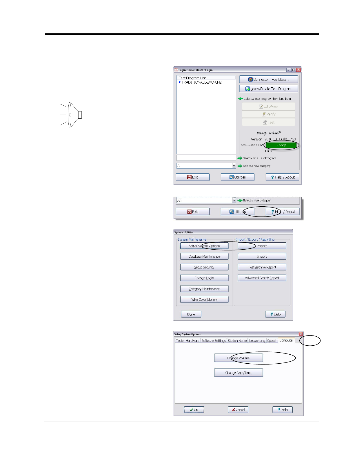
The Easy-Wire software relies on sound prompts to provide test feedback to the operator.
1. In the Easy-Wire main menu,
click the green status indicator.
You should hear two trumpet
sounds coming from the tester.
2. If you hear the sounds, skip
to “Connecting to a Network”
on page 14.
If you do not hear the sounds,
continue with the steps below.
3. From the Easy-Wire main
menu, click Utilities.
4. Click Setup System Options.
5. Open the “Computer” tab and
click Change Volume.

Checking the System 16
6. Adjust the volume slider and
click Test to try out the setting.
7. When the volume is at the desired
level, click Done.
8. The “Setup System Options” window
will be open. Click OK.
9. The “System Utilities” window will
be open. Click Done to return to the
main menu.
10. If you are still having sound problems, try the following:
•Verify that speakers are connected to the PC and have power.
•Verify that the speakers are on and that the volume is turned up.
•Verify that the volume on your PC is turned up (the PC volume
control can be found on your Windows task bar).
If the sound problem persists, call Cirris for assistance.

Completing a Network Install 17
CONNECTING TO A NETWORK
Setting up a network should be done by your IT personnel and is outside the scope of this
manual. This section describes how to share data between testers on an existing network.
Choose the option below that best fits your requirements:
A. Connecting new CH2 testers to a new network database server
This option requires the Cirris Server Software. If you do not have a copy already,
contact your Cirris sales representative.
B. Connecting new CH2 testers to an existing network database server
This network can include the Easy-Touch, CR, CH2, and CH+ testers all using the same
network database server with Cirris Server Software installed.
C. Changing existing stand-alone testers to a network installation
If you want to save existing test data, you can select one tester as the source for the
network database server. The data on this tester will re-populate the Cirris database
server install and overwrite any existing data on your network server. Test programs that
are unique to the network database server from your remaining testers will need to be
exported to a flash drive and then imported into a new network database.
Other manuals for CH2
6
Table of contents
Other Cirris Test Equipment manuals

Cirris
Cirris CH2 User manual

Cirris
Cirris 4200 Series User manual

Cirris
Cirris CH2 User manual

Cirris
Cirris CH2 User manual

Cirris
Cirris Touch 1 User manual

Cirris
Cirris signature 1100R+ User manual

Cirris
Cirris CH2 User manual

Cirris
Cirris CH2 User manual

Cirris
Cirris easy-wire CR User manual

Cirris
Cirris 4200 Series User manual

Cirris
Cirris CR User manual

Cirris
Cirris CR User manual

Cirris
Cirris CR User manual

Cirris
Cirris Easy-Touch Pro User manual

Cirris
Cirris CH+ User manual

Cirris
Cirris 4200 Series User manual

Cirris
Cirris 4200 Series User manual

Cirris
Cirris CH2 User manual

Cirris
Cirris Easy-Touch Pro User manual

Cirris
Cirris Touch1 LV Installation and operation manual


