Cobra 1046 User manual

MANUALE INSTALLAZIONE
INSTALLATION MANUAL
EINBAUANLEITUNG
NOTICE DE MONTAGE
HANDLEIDING VOOR DE INSTALLATIE
MANUAL DE INSTALACION
Art. 1046
CAR SECURITY

CAR SECURITY
CAR SECURITY
COMPOSIZIONE DEL KIT
KIT CONTENTS
BESTANDTEILE DES
NACHRÜSTSATZES
COMPOSITION DU KIT
INHOUD KIT
COMPONENTES DEL KIT

GB
D
F
NL
E
I
• Staccare la parte centrale contenente lo schema elettrico.
•
Remove the central section containing the electric layout.
• Den mittleren Teil mit dem Verkabelungsdiagramm.
•
Enlever la partie centrale contenant le schéma électrique.
• Verwijder het middelste gedeelte, dat het elektrisch schema.
•
Arrancar la parte central, con el esquema electrico.


5
L’Art. 1046 consente di comandare a distanza le porte, la cui apertura e chiusura
è segnalata dagli indicatori di direzione. Il prodotto è di applicazione universale e
permette di ottenere anche la chiusura dei vetri elettrici - senza l’aggiunta di alcun
modulo - nei casi in cui la vettura sia provvista in origine della funzione comfort.
COLLEGAMENTI ELETTRICICOLLEGAMENTI ELETTRICI
COLLEGAMENTI ELETTRICI
• Collegare il filo ROSSO ad un positivo +30 (possibilmente a valle di un fusibile
originale dell’auto).
• Collegare il filo NERO ad una connessione originale di massa o al telaio
dell’auto.
• Collegare il filo VERDE-ROSSO ad un positivo +15 .
• Collegare i fili GIALLO ai fili dell’auto che alimentano gli indicatori di direzione.
• Collegare il filo MARRONE-BIANCO ad un modulo supplementare a comando
negativo per la chiusura dei vetri.
ATTENZIONE: per auto dotate di chiusura vetri comfort di tipo negativo è
possibile collegare direttamente il filo MARRONE-BIANCO al filo di comando
chiusura vetri dell’auto. Se serve un comando positivo è necessario interporre
un relè invertitore.
• Collegare i restanti fili ARANCIO, VIOLA, GIALLO-NERO, GRIGIO-NERO,
ARANCIO-BIANCO, VIOLA-BIANCO come da schema “chiusure
centralizzate”.
APPLICAZIONE ETICHETTE DI OMOLOGAZIONEAPPLICAZIONE ETICHETTE DI OMOLOGAZIONE
APPLICAZIONE ETICHETTE DI OMOLOGAZIONE
I radiocomandi vengono forniti con i marchi di
omologazione validi per Germania e Inghilterra.
I restanti numeri di omologazione sono riportati sulle
etichette adesive fornite. Applicate quella
contrassegnata con la sigla del Vostro Paese come
indicato in figura.
I

6
ATTENZIONEATTENZIONE
ATTENZIONE
Durante la programmazione degli switch fare molta attenzione a non spostareDurante la programmazione degli switch fare molta attenzione a non spostare
Durante la programmazione degli switch fare molta attenzione a non spostare
inavvertitamente nella posizione ON lo switch n. 2. Tale operazione infattiinavvertitamente nella posizione ON lo switch n. 2. Tale operazione infatti
inavvertitamente nella posizione ON lo switch n. 2. Tale operazione infatti
provoca la cancellazione dei codici dei radiocomandi dalla memoria delprovoca la cancellazione dei codici dei radiocomandi dalla memoria del
provoca la cancellazione dei codici dei radiocomandi dalla memoria del
modulo.Dovranno quindi essere rimemorizzati secondo la procedura dimodulo.Dovranno quindi essere rimemorizzati secondo la procedura di
modulo.Dovranno quindi essere rimemorizzati secondo la procedura di
AUTOAPPRENDIMENTO DEI RADIOCOMANDI descritta in questo manuale.AUTOAPPRENDIMENTO DEI RADIOCOMANDI descritta in questo manuale.
AUTOAPPRENDIMENTO DEI RADIOCOMANDI descritta in questo manuale.
UTILIZZO DEGLI SWITCHUTILIZZO DEGLI SWITCH
UTILIZZO DEGLI SWITCH
1234
OFF
ON
1234
OFF
ON
1234
OFF
ON
1234
OFF
ON
Per vetture con chiusura di tipo elettrico (durata comandi
apri e chiudi di 1 sec.). Posizionando ON lo switch 1 si
ottiene una durata del comando pari a 0.2 sec.
È attiva l’uscita MARRONE/BIANCO da collegare al
filo di comando comfort del sistema originale della
vettura. L’uscita è attiva fino al rilascio del pulsante
del radiocomando.
Attivazione della procedura di autoapprendimento di
nuovi radiocomandi.
Per vetture con sistema comfort che funziona
prolungando il comando di chiusura porte (durata dei
comandi apri e chiudi pari al tempo di pressione del
pulsante del radiocomando).
Per vetture con chiusura di tipo pneumatico (durata
comandi apri e chiudi di 4 sec.).

7
AUTOAPPRENDIMENTO DEI RADIOCOMANDIAUTOAPPRENDIMENTO DEI RADIOCOMANDI
AUTOAPPRENDIMENTO DEI RADIOCOMANDI
Questo modulo viene fornito con due radiocomandi già abbinati.
Qualora vi sia necessità di abbinare un nuovo radiocomando procedere come segue:
1.1.
1.1.
1. Premere il pulsante “B” del radiocomando già abbinato per sbloccare le porte.
2.2.
2.2.
2. Posizionare lo switch 2 del modulo su ON.
3.3.
3.3.
3. Premere entrambi i pulsanti del radiocomando fino a che il LED diventa da
lampeggiante a spento. Rilasciare i pulsanti (il LED si accende in modo fisso).
4.4.
4.4.
4. Premere il pulsante 'A' del radiocomando e verificare che il LED lampeggi.
La procedura di autoapprendimento è terminata.
5.5.
5.5.
5. Ripetere le operazioni del punto n.3 per il secondo radiocomando.
6.6.
6.6.
6. Riportare lo switch 2 su OFF.
7.7.
7.7.
7. Premere nuovamente il pulsante 'A' dei radiocomandi per verificare che il
prodotto funzioni correttamente.
I
A
B
OK
7
1234
OFF
6
AB
1234
ON
2
AB
3
AB
A
B
1
4
5
mod. 7777
OK
7
1234
OFF
6
1 234
ON
2 3
1
5
B
A
B
A
B
A
4
B
A
B
A
mod. 7727

8
RICERCA DEI GUASTIRICERCA DEI GUASTI
RICERCA DEI GUASTI
•Il radiocomando non funziona:Il radiocomando non funziona:
Il radiocomando non funziona:Il radiocomando non funziona:
Il radiocomando non funziona:
Controllare la posizione dello switch n°switch n°
switch n°switch n°
switch n° 2 che deve essere sempre OFF.2 che deve essere sempre OFF.
2 che deve essere sempre OFF.2 che deve essere sempre OFF.
2 che deve essere sempre OFF.
Se questo switch viene inavvertitamente spostato nella posizione ON ciò
provoca la cancellazione dei codici dei radiocomandi dalla memoria del
modulo. Dovranno quindi essere rimemorizzati secondo la procedura di
AUTOAPPRENDIMENTO DEI RADIOCOMANDI descritta in questo manuale.
•I lampeggiatori non si accendono all'inserimento / disinserimento:I lampeggiatori non si accendono all'inserimento / disinserimento:
I lampeggiatori non si accendono all'inserimento / disinserimento:I lampeggiatori non si accendono all'inserimento / disinserimento:
I lampeggiatori non si accendono all'inserimento / disinserimento:
controllare con una lampada spia che sui due fili di colore GIALLO sia
presente il comando positivo (due impulsi all'inserimento e uno al
disinserimento). Se questo comando è presente, il guasto é da ricercarsi
nelle connessioni sull'auto.
•Le chiusure centralizzate non funzionano:Le chiusure centralizzate non funzionano:
Le chiusure centralizzate non funzionano:Le chiusure centralizzate non funzionano:
Le chiusure centralizzate non funzionano:
controllare lo stato dei fusibili posti nei fili del cablaggio. Se i fusibili sono
bruciati, é necessario ricercare l'errata connessione prima di sostituirli.
CARATTERISTICHE TECNICHE DEL SISTEMACARATTERISTICHE TECNICHE DEL SISTEMA
CARATTERISTICHE TECNICHE DEL SISTEMA
Tensione nominale di alimentazione .................................................... 12 VDC
Tensione d’esercizio ......................................................................... 9 /16 VDC
Consumo di corrente a 12 VDC ................................................................ 5 mA
Temperatura d'esercizio .................................................................. -40° +85°C
Chiusura dei vetri comando negativo................................................... max 1 A

Art. 1046 is used to remote control doors whose unlocking and locking movements
are indicated by direction indicators. The product can be universally installed
and can also be used to wind up electric windows without the addition of any
other module if the vehicle in question was already originally equipped with the
comfort function.
ELECTRICAL CONNECTIONSELECTRICAL CONNECTIONS
ELECTRICAL CONNECTIONS
• Connect the RED wire to a +30 positive source (possibly on the load side of
an original fuse in the car).
• Connect the BLACK wire to an original ground connection or to the chassis of
the car.
• Connect the GREEN-RED wire to a +15 positive source.
• Connect the YELLOW wires to the car wires that power the turn indicators.
• Connect the BROWN-WHITE wire to a supplementary negative control module
to wind up the windows.
ATTENTION: the BROWN-WHITE wire can be directly connected to the
window-winding control wire of the car in vehicles equipped with comfort
window winding systems of the negative type. An inverter relay must be
installed if a positive command is required.
• Connect the remaining ORANGE, VIOLET, YELLOW-BLACK, GREY-BLACK,
ORANGE-WHITE and VIOLET-WHITE wires as shown in the “central lock”
diagram.
APPLYING APPROVAL LABELSAPPLYING APPROVAL LABELS
APPLYING APPROVAL LABELS
The radio controls are supplied with approval labels
valid for Germany and Great Britain.
The remaining approval numbers are given on the
supplied stickers. Affix the one bearing the code of
your country as indicated in the figure.
GB
9

10
ATTENTIONATTENTION
ATTENTIONATTENTION
ATTENTION
When programming the switches, take great care to prevent switch N° 2When programming the switches, take great care to prevent switch N° 2
When programming the switches, take great care to prevent switch N° 2
from being accidentally set to the ON position. This would cancel the codesfrom being accidentally set to the ON position. This would cancel the codes
from being accidentally set to the ON position. This would cancel the codes
of the radio controls from the memory of the module. If this happens, theof the radio controls from the memory of the module. If this happens, the
of the radio controls from the memory of the module. If this happens, the
codes must be memorized again in compliance with the RADIO CONTROLcodes must be memorized again in compliance with the RADIO CONTROL
codes must be memorized again in compliance with the RADIO CONTROL
AUTO-LEARNING procedure described in this manual.AUTO-LEARNING procedure described in this manual.
AUTO-LEARNING procedure described in this manual.
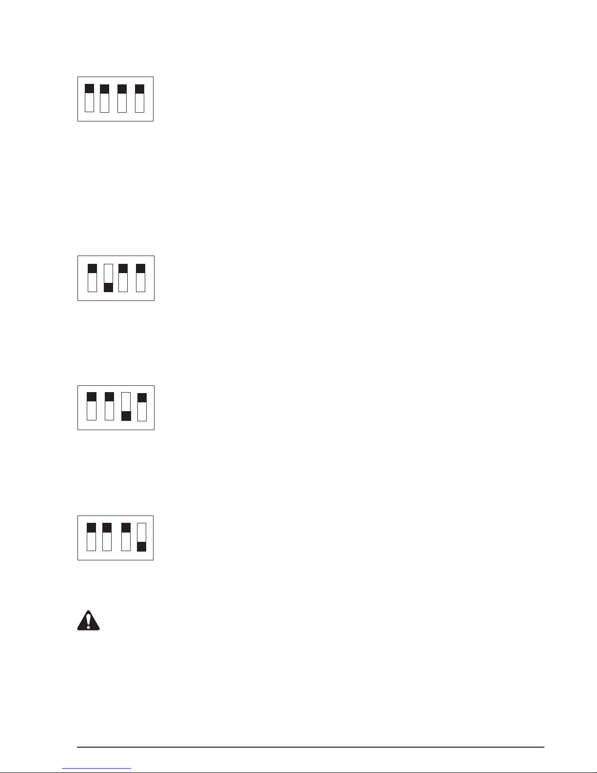
USE OF THE SWITCHESUSE OF THE SWITCHES
USE OF THE SWITCHES
1234
OFF
ON
1234
OFF
ON
1234
OFF
ON
1234
OFF
ON
For vehicles with electric locks (unlock and lock
commands lasting 1 sec.). Set switch 1 to the ON
position to obtain a command lasting 0.2 sec.
The BROWN/WHITE output is activated and should
be connected to the comfort control wire of the original
system in the vehicle. The output remains activated
until the button on the radio control is released.
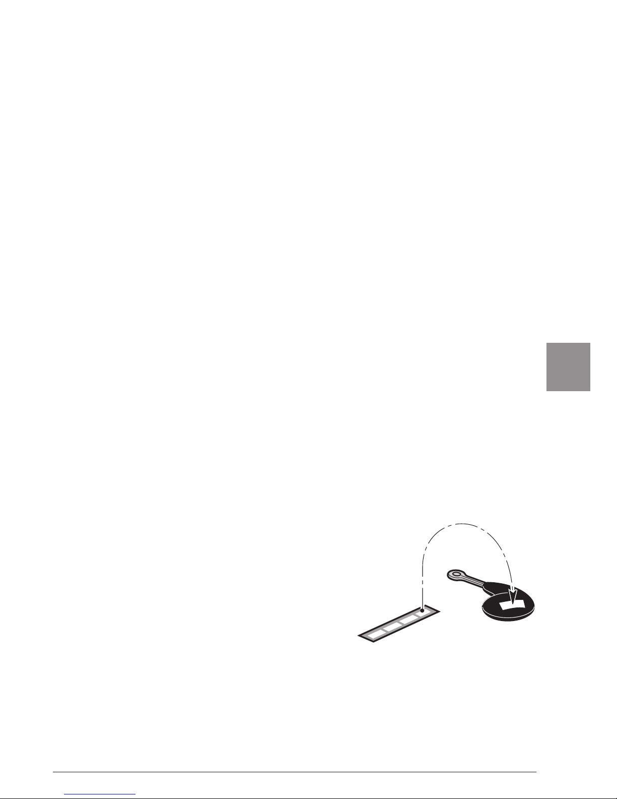
Activation of the auto-learning procedure for new radio
controls.
For vehicles with comfort systems that operate by
lengthening the door locking command (the unlock and
lock commands last for as long as the button on the
radio control remains depressed).
For vehicles with locks of the pneumatic type (unlock
and lock commands lasting 4 sec.).

11
RADIO CONTROL AUTO-LEARNING MODERADIO CONTROL AUTO-LEARNING MODE
RADIO CONTROL AUTO-LEARNING MODE
This module is supplied with two already matched radio controls.
Proceed in the following way if another radio control is required:
1.1.
1.1.
1. Press button “B” on the already programmed radio control to unlock the doors.
2.2.
2.2.
2. Set switch 2 on the module to the ON position.
3.3.
3.3.
3. Press both buttons on the radio control until the LED changes from flashing
to off. Release the buttons (the LED will remain permanently on).
4.4.
4.4.
4. Press button “A” on the radio control and make sure that the LED flashes.
The auto-learning procedure has now terminated.
5.5.
5.5.
5. Repeat the operations described in point N° 3 for the second radio control.
6.6.
6.6.
6. Set switch 2 back to the OFF position.
7.7.
7.7.
7. Press button “A” on the radio control again to make sure that the product
operates correctly.
GB
A
B
OK
7
1234
OFF
6
AB
1234
ON
2
AB
3
AB
A
B
1
4
5
mod. 7777
OK
7
1234
OFF
6
1 234
ON
2 3
1
5
B
A
B
A
B
A
4
B
A
B
A
mod. 7727

12
TROUBLESHOOTINGTROUBLESHOOTING
TROUBLESHOOTING
•The radio control fails to operate:The radio control fails to operate:
The radio control fails to operate:The radio control fails to operate:
The radio control fails to operate:
Check the position of switch N° 2 which must always be OFFswitch N° 2 which must always be OFF
switch N° 2 which must always be OFFswitch N° 2 which must always be OFF
switch N° 2 which must always be OFF. The codes
of the radio controls will have been cancelled from the memory of the module
if this switch has been accidentally set to the ON position and must therefore
be memorized again as indicated in the RADIO CONTROL AUTO-
LEARNING MODE procedure described in this manual.
•The hazard lights fail to come on when the system is armed/disarmed:The hazard lights fail to come on when the system is armed/disarmed:
The hazard lights fail to come on when the system is armed/disarmed:The hazard lights fail to come on when the system is armed/disarmed:
The hazard lights fail to come on when the system is armed/disarmed:
Use a warning light to check that the positive command is transmitted in the
two YELLOW coloured wires (two pulses on arming and one on disarming).
If this command is present, check for faults in the car connections.
•The central locks fail to operate:The central locks fail to operate:
The central locks fail to operate:The central locks fail to operate:
The central locks fail to operate:
Check the condition of the fuses in the harness wires. If the fuses have
burnt out, identify the incorrect connection before changing them.
TECHNICAL FEATURES OF THE SYSTEMTECHNICAL FEATURES OF THE SYSTEM
TECHNICAL FEATURES OF THE SYSTEM
Power source voltage rating .................................................................. 12 VDC
Operating voltage rating .................................................................... 9 /16 VDC
Power draw at 12 VDC .............................................................................. 5 mA
Operating temperature .................................................................... -40° +85°C
Window winding with negative command ............................................ max 1 A

13
Der Artikel 1046 gestattet das ferngesteuerte Betätigen der Türen, wobei Öffnen
und Schließen durch die Richtungsanzeiger gemeldet werden. Der Artikel läßt
sich allgemein einsetzen und ist auch - ohne zusätzlichen Einbau irgendeines
Teils - zum Schließen der Fenster geeignet, falls das Fahrzeug ursprünglich
schon mit der Komfortfunktion ausgestattet war.
ELEKTRISCHE ANSCHLÜSSEELEKTRISCHE ANSCHLÜSSE
ELEKTRISCHE ANSCHLÜSSE
• Die ROTE Leitung an +30 positiv anschließen (möglichst stromab von der
Originalsicherung des Fahrzeugs).
• Die SCHWARZE Leitung an den Original-Massestecker oder das Fahrgestell
des Fahrzeugs anschließen.
• Die GRÜN-ROTE Leitung an +15 positiv anschließen.
• Die GELBEN Leitungen an die Leitungen für den Stromanschluß der
Richtungsanzeiger des Fahrzeugs anschließen.
ACHTUNG: Bei Fahrzeugen mit negativ angesteuerter Komfortschließung
der Fenster kann man die BRAUN/WEISSE Leitung direkt an die Leitung zur
Ansteuerung des Fensterhebers des Fahrzeugs anschließen. Liegt eine
positive Ansteuerung vor, ist ein Polumschalterelais erforderlich.
• Die restlichen Leitungen, d.h. ORANGE, VIOLETT, GELB/SCHWARZ, GRAU/
SCHWARZ, ORANGE/WEISS, VIOLETT/WEISS gemäß des Anschlußplans
“Zentralverriegelung” anschließen.
ANBRINGUNG DER AUFKLEBER MIT DEN PRÜFZEICHENANBRINGUNG DER AUFKLEBER MIT DEN PRÜFZEICHEN
ANBRINGUNG DER AUFKLEBER MIT DEN PRÜFZEICHEN
Die Handsender sind bei der Auslieferung mit dem
Prüfzeichen für Deutschland und England versehen.
Die restlichen Prüfzeichen befinden sich auf den zum
Lieferumfang gehörenden Aufklebern. Das
Prüfzeichen des jeweiligen Landes wie in der
Abbildung gezeigt anbringen.
D

14
ACHTUNGACHTUNG
ACHTUNGACHTUNG
ACHTUNG
Bei der Programmierung der DIP-Schalter unbedingt darauf achten, daßBei der Programmierung der DIP-Schalter unbedingt darauf achten, daß
Bei der Programmierung der DIP-Schalter unbedingt darauf achten, daß
man den Dip-Schalter Nr. 2 nicht unbeabsichtigt auf ON stellt, denn diesman den Dip-Schalter Nr. 2 nicht unbeabsichtigt auf ON stellt, denn dies
man den Dip-Schalter Nr. 2 nicht unbeabsichtigt auf ON stellt, denn dies
würde zum Löschen des Speichers der Handsender führen. In diesen Fallwürde zum Löschen des Speichers der Handsender führen. In diesen Fall
würde zum Löschen des Speichers der Handsender führen. In diesen Fall
sind sie erneut zu programmieren, und zwar mit dem Vorgang, der sichsind sie erneut zu programmieren, und zwar mit dem Vorgang, der sich
sind sie erneut zu programmieren, und zwar mit dem Vorgang, der sich
EINLERNEN DER HANDSENDER nennt und in diesem HandbuchEINLERNEN DER HANDSENDER nennt und in diesem Handbuch
EINLERNEN DER HANDSENDER nennt und in diesem Handbuch
beschrieben ist.beschrieben ist.
beschrieben ist.
BENUTZUNG DER DIP-SCHALTERBENUTZUNG DER DIP-SCHALTER
BENUTZUNG DER DIP-SCHALTER
1234
OFF
ON
1234
OFF
ON
1234
OFF
ON
1234
OFF
ON
Für Fahrzeuge mit elektrischer Verriegelung (Dauer des
Befehls Öffnen und Schließen 1 Sekunde). Dip-
Schalter Nr. 1 auf ON stellen, um eine Befehlsdauer
von 0,2 Sekunden zu erhalten.
Der BRAUN/WEISSE Ausgang ist aktiv und muß an
die Originalleitung der Komfortsteuerung des
Fahrzeugs angeschlossen werden. Der Ausgang ist
aktiv, bis man die Taste des Handsenders losläßt.
Aktivierung des Einlernverfahren für neue Handsender.
Für Fahrzeuge mit Komfortschließung, die mit
Verlängerung des Befehls zum Türschließen
funktionieren (Dauer der Befehle Öffnen und Schließen
entspricht der Zeitdauer der Betätigung der Taste des
Handsenders).
Für Fahrzeuge mit pneumatischer Verriegelung (Dauer
des Befehls Öffnen und Schließen 4 Sekunden).

15
EINLERNEN DER HANDSENDEREINLERNEN DER HANDSENDER
EINLERNEN DER HANDSENDER
Dieses Modul wird mit zwei Handsendern ausgeliefert, die schon programmiert
sind.Falls ein neuer Handsender zu programmieren ist, wie folgt vorgehen:
1.1.
1.1.
1. Die Taste “B” des schon programmierten Handsenders drücken, um die Türen zu
entriegeln.
2.2.
2.2.
2. Den Dip-Schalter 2 des Moduls auf ON stellen.
3.3.
3.3.
3. Beide Tasten des Handsenders drücken, bis die LED-Anzeige, die bisher blinkte,
ausgeht. Die Tasten loslassen (dabei leuchtet die LED-Anzeige mit Konstantlicht auf).
4.4.
4.4.
4. Die Taste ‘A’ des Handsenders drücken und prüfen, ob die LED-Anzeige aufblinkt.
Der Einlernvorgang ist damit beendet.
5.5.
5.5.
5. Für den zweiten Handsender die Vorgänge ab Punkt 2 wiederholen.
6.6.
6.6.
6. Den Dip-Schalter Nr. 2 wieder auf OFF stellen.
7.7.
7.7.
7. Die Taste ‘A’ der Handsender erneut drücken, um zu prüfen, ob sie einwandfrei
funktionieren.
D
A
B
OK
7
1234
OFF
6
AB
1234
ON
2
AB
3
AB
A
B
1
4
5
mod. 7777
OK
7
1234
OFF
6
1 234
ON
2 3
1
5
B
A
B
A
B
A
4
B
A
B
A
mod. 7727

16
FEHLERSUCHEFEHLERSUCHE
FEHLERSUCHE
•Der Handsender funktioniert nicht:Der Handsender funktioniert nicht:
Der Handsender funktioniert nicht:Der Handsender funktioniert nicht:
Der Handsender funktioniert nicht:
Die Stellung von Dip-Schalter Nr. 2 prüfen, der immer auf OFF stehenDip-Schalter Nr. 2 prüfen, der immer auf OFF stehen
Dip-Schalter Nr. 2 prüfen, der immer auf OFF stehenDip-Schalter Nr. 2 prüfen, der immer auf OFF stehen
Dip-Schalter Nr. 2 prüfen, der immer auf OFF stehen
muß.muß.
muß.muß.
muß. Wird dieser Dip-Schalter unbeabsichtigt auf ON gestellt, führt das zum
Löschen der Codenummern des Handsenders im Speicher des Moduls. Dann
müssen die Handsender nach dem Verfahren, das EINLERNEN DER
HANDSENDER genannt ist und in diesem Handbuch beschrieben wird, neu
programmiert werden.
•Die Blinker leuchten bei Einschalten/Ausschalten nicht auf:Die Blinker leuchten bei Einschalten/Ausschalten nicht auf:
Die Blinker leuchten bei Einschalten/Ausschalten nicht auf:Die Blinker leuchten bei Einschalten/Ausschalten nicht auf:
Die Blinker leuchten bei Einschalten/Ausschalten nicht auf:
Mit einer Testlampe prüfen, ob auf den beiden GELBEN Leitungen das positive
Signal vorliegt (zwei Impulse beim Einschalten und ein Impuls beim
Ausschalten). Wenn dieses Signal nicht vorliegt, sind die Anschlüsse im
Fahrzeug zu prüfen.
•Die Zentralverriegelung funktioniert nicht:Die Zentralverriegelung funktioniert nicht:
Die Zentralverriegelung funktioniert nicht:Die Zentralverriegelung funktioniert nicht:
Die Zentralverriegelung funktioniert nicht:
Den Zustand der Sicherungen an den Kabelbäumen prüfen. Sind die
Sicherungen durchgebrannt, muß vor dem Ersetzen der Sicherungen der
falsche Anschluß gefunden werden.
TECHNISCHE DATEN DES SYSTEMSTECHNISCHE DATEN DES SYSTEMS
TECHNISCHE DATEN DES SYSTEMS
Nominale Anschlußspannung .............................................................. 12 V GS
Betriebsspannung ............................................................................. 9/16 V GS
Stromverbrauch bei 12 V GS .................................................................... 5 mA
Betriebstemperatur ................................................................... -40° bis +85°C
Fensterschließen mit negativer Ansteuerung....................................... max. 1A

17
L’Art. 1046 permet la commande à distance des portes. L’ouverture et la fermeture
sont signalées par les indicateurs de direction. Un produit d’application universelle
qui permet d’obtenir aussi la fermeture des vitres électriques sans ajouter aucun
module, si la voiture est équipée d’origine de la fonction confort.
BRANCHEMENTS ELECTRIQUESBRANCHEMENTS ELECTRIQUES
BRANCHEMENTS ELECTRIQUES
• Connecter le fil ROUGE à un positif +30 (si possible en aval d’un fusible
original de la voiture).
• Connecter le fil NOIR à une connexion originale de masse ou au châssis de
la voiture.
• Connecter le fil VERT-ROUGE à un positif +15.
• Connecter le fil JAUNE aux fils de la voiture qui alimentent les indicateurs de
direction.
• Connecter le fil MARRON-BLANC à un module supplémentaire à commande
négative pour la fermeture des vitres.
ATTENTION : pour les voitures équipées de fermeture des vitres confort à
commande négative, il est possible de relier directement le fil MARRON-
BLANC au fil qui commande la fermeture des vitres de la voiture. Interposer
un relais inverseur s’il faut une commande positive.
• Connecter les fils restants ORANGE, VIOLET, JAUNE-NOIR, GRIS-NOIR,
ORANGE-BLANC, VIOLET-BLANC conformément au schéma «verrouillages
centralisés».
APPLICATION DES ETIQUETTES D’HOMOLOGATIONAPPLICATION DES ETIQUETTES D’HOMOLOGATION
APPLICATION DES ETIQUETTES D’HOMOLOGATION
Les radiocommandes sont fournies avec les marques
d’homologation valables pour l’Allemagne et
l’Angleterre.
Les numéros d’homologation restants figurent sur les
étiquettes adhésives fournies. Appliquez l’étiquette
identifiée par le sigle de votre Pays, de la manière
indiquée sur la figure.
F

18
ATTENTIONATTENTION
ATTENTIONATTENTION
ATTENTION
Pendant la programmation des commutateurs, faites très attention à nePendant la programmation des commutateurs, faites très attention à ne
Pendant la programmation des commutateurs, faites très attention à ne
pas mettre par inadvertance le commutateur n. 2 sur la position ON. Enpas mettre par inadvertance le commutateur n. 2 sur la position ON. En
pas mettre par inadvertance le commutateur n. 2 sur la position ON. En
effet, cette opération provoque l’effacement des codes deseffet, cette opération provoque l’effacement des codes des
effet, cette opération provoque l’effacement des codes des
radiocommandes de la mémoire du module. Il faudra donc les mémoriserradiocommandes de la mémoire du module. Il faudra donc les mémoriser
radiocommandes de la mémoire du module. Il faudra donc les mémoriser
de nouveau en suivant la procédure d’AUTO-APPRENTISSAGE DESde nouveau en suivant la procédure d’AUTO-APPRENTISSAGE DES
de nouveau en suivant la procédure d’AUTO-APPRENTISSAGE DES
RADIOCOMMANDES décrite dans ce manuel.RADIOCOMMANDES décrite dans ce manuel.
RADIOCOMMANDES décrite dans ce manuel.
UTILISATION DES COMMUTATEURSUTILISATION DES COMMUTATEURS
UTILISATION DES COMMUTATEURS
1234
OFF
ON
1234
OFF
ON
1234
OFF
ON
1234
OFF
ON
Pour les voitures avec verrouillage de type électrique
(durée des commandes d’ouverture et de fermeture 1
s.). En mettant le commutateur 1 sur ON, on obtient
une durée de la commande de 0,2 s.
La sortie MARRON/BLANC est active ; il faut la relier
au fil de commande confort du système original de la
voiture. La sortie est active tant que le bouton de la
radiocommande ne sera pas relâché.
Activation de la procédure d’apprentissage de
nouvelles radiocommandes.
Pour les voitures dont le système de confort fonctionne
en prolongeant la commande de fermeture des portes
(durée des commandes d’ouverture et de fermeture
égale au temps pendant lequel vous appuyez sur le
bouton de la radiocommande).
Pour les voitures avec verrouillage de type mécanique
(durée des commandes d’ouverture et de fermeture
de 4 s.).

19
AUTO-APPRENTISSAGE DES RADIOCOMMANDESAUTO-APPRENTISSAGE DES RADIOCOMMANDES
AUTO-APPRENTISSAGE DES RADIOCOMMANDES
Ce module est fourni avec deux radiocommandes déjà associées.S’il est nécessaire
d’y associer une nouvelle radiocommande, la procédure est la suivante :
1.1.
1.1.
1. Pour déverrouiller les portes, appuyer sur le bouton “B” de la radiocommande
déjà associée.
2.2.
2.2.
2. Mettez le commutateur 2 du module sur ON.
3.3.
3.3.
3. Appuyez sur les deux boutons de la radiocommande jusqu’à quand l’indicateur LED
clignotant s’éteindra. Relâchez les boutons (le LED s’allume de manière fixe).
4.4.
4.4.
4. Appuyez sur le bouton «A» de la radiocommande. Le LED doit clignoter. La procédure
d’auto-apprentissage est terminée.
5.5.
5.5.
5. Répétez cette procédure à partir du point n. 3 pour la deuxième radiocommande.
6.6.
6.6.
6. Remettez le commutateur 2 sur OFF.
7.7.
7.7.
7. Appuyez de nouveau sur le bouton «A» de la radiocommande pour vérifier que le
produit fonctionne correctement.
F
A
B
OK
7
1234
OFF
6
AB
1234
ON
2
AB
3
AB
A
B
1
4
5
mod. 7777
OK
7
1234
OFF
6
1 234
ON
2 3
1
5
B
A
B
A
B
A
4
B
A
B
A
mod. 7727

20
RECHERCHE DES DEFAUTSRECHERCHE DES DEFAUTS
RECHERCHE DES DEFAUTS
•La radiocommande ne fonctionne pas :La radiocommande ne fonctionne pas :
La radiocommande ne fonctionne pas :La radiocommande ne fonctionne pas :
La radiocommande ne fonctionne pas :
Vérifiez la position du commutateur n° 2 qui doit être toujours sur OFFcommutateur n° 2 qui doit être toujours sur OFF
commutateur n° 2 qui doit être toujours sur OFFcommutateur n° 2 qui doit être toujours sur OFF
commutateur n° 2 qui doit être toujours sur OFF.
S’il est mis par inadvertance sur la position ON, il provoque l’effacement des
codes des radiocommandes de la mémoire du module.
Il faudra donc les mémoriser de nouveau suivant la procédure d’AUTO-
APPRENTISSAGE DES RADIOCOMMANDES décrite dans ce manuel.
•Les indicateurs de direction ne s’allument pas à l’activation / désactivation :Les indicateurs de direction ne s’allument pas à l’activation / désactivation :
Les indicateurs de direction ne s’allument pas à l’activation / désactivation :Les indicateurs de direction ne s’allument pas à l’activation / désactivation :
Les indicateurs de direction ne s’allument pas à l’activation / désactivation :
Vérifiez à l’aide d’un témoin lumineux que la commande positive (deux
impulsions à l’activation et une impulsion à la désactivation) est présente sur
les deux fils couleur JAUNE. Si cette commande est présente, rechercher le
défaut dans les connexions de la voiture.
•Le verrouillage centralisé ne fonctionne pas :Le verrouillage centralisé ne fonctionne pas :
Le verrouillage centralisé ne fonctionne pas :Le verrouillage centralisé ne fonctionne pas :
Le verrouillage centralisé ne fonctionne pas :
Vérifiez l’état des fusibles qui se trouvent dans les fils du câblage. Si les
fusibles ont brûlé, vous devez rechercher la connexion erronée avec de les
remplacer.
CARACTERISTIQUES TECHNIQUES DU SYSTEMECARACTERISTIQUES TECHNIQUES DU SYSTEME
CARACTERISTIQUES TECHNIQUES DU SYSTEME
Tension nominale d’alimentation .......................................................... 12 V CC
Tension de fonctionnement ............................................................... 9/16 V CC
Consommation de courant à 12 V CC ...................................................... 5 mA
Température de fonctionnement ..................................................... -40° +85°C
Fermeture des vitres à commande négative........................................ max. 1A
Other manuals for 1046
1
Table of contents
Languages:
Other Cobra Car Alarm manuals

Cobra
Cobra 1046 User manual

Cobra
Cobra 8510 User manual

Cobra
Cobra Bridge 4100 User manual

Cobra
Cobra 4625 User manual

Cobra
Cobra Bridge 4100 User manual

Cobra
Cobra Connex ICD31 User manual

Cobra
Cobra 4625 User manual

Cobra
Cobra G100 User manual

Cobra
Cobra Connex Guardian 222X User manual

Cobra
Cobra Bridge compact alarm User manual
Popular Car Alarm manuals by other brands

Nordic Start
Nordic Start NA-200 user guide

Autostart
Autostart AS-2510 TW Wiring schematic

Auto Page
Auto Page RF-700 Operation instructions

Prime Security
Prime Security 98 installation manual

Omega Research & Development
Omega Research & Development Excalibur Gold ATV Series Comprehensive Installer Technical Guide

RHINO
RHINO GTS installation manual