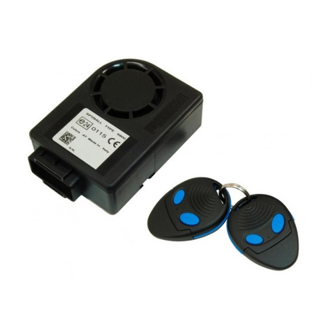
Cobra G100 User manual

G100 - G300
MANUALE UTENTE E INSTALLATORE
USER AND FITTING INSTRUCTIONS
MANUEL UTILISATEUR ET INSTALLATION
MANUAL DEL USUARIO Y INSTALADOR
MANUAL DE USO E INSTALAÇÃO
UŽIVATELSKÝ NÁVOD
A INSTALATÉRA
ANVÄNDAR OCH INSTALLATTIONSHANDBOK
BRUKERMANUAL OG INSTALLATØRMANUAL
BRUGERMANUAL OG INSTALLATØRMANUAL
MONTAGE BEDIENUNGSANLEITUNG
06DE2245D OK.pmd 09/09/2008, 10.061

MANUALE UTENTE E INSTALLATORE G100
I
2
G100
Gentile cliente,
nelringraziarlaperlasceltafatta,lainformiamochequestoprodottoèunsistemadiallarmetecnologicamenteavanzato,rispondente
agli standards di prestazioni definiti dalle case automobilistiche e conforme alle direttive comunitarie.
A Lei, gentile utente, dopo l’installazione del sistema sono stati consegnati i radiocomandi (ove previsti) ed il manuale utente che
contiene anche la dichiarazione di conformità del prodotto ed il relativo certificato di installazione.
Il manuale è suddiviso in 11 parti:
Pagina 3 1 -LEGENDAE CONTENUTO DELKIT.
5 2 -INFORMAZIONI.
63-INTRODUZIONE.
7 4 -ELENCO FUNZIONI.
8 5 -ISTRUZIONI IN BREVE.
96-POSIZIONAMENTO DEGLI ELEMENTI DEL SISTEMA.
10 7 -COME CONFIGURARE L’INGRESSO PERIMETRIAPOSITIVO.
10 8 -MEMORIAD’ALLARME.
10 9 -CARATTERISTICHE TECNICHE DI SISTEMA.
88 - 113 SCHEMI.
194-200 GARANZIE.
Legga il manuale con attenzione: trarrà la massima soddisfazione dal prodotto acquistato.
Le consigliamo inoltre di conservare questo manuale insieme ai documenti dell’auto per una più facile consultazione in caso di
necessità. Qualora si manifesti un problema non risolvibile, si rivolga direttamente al suo installatore di fiducia.
06DE2245D OK.pmd 09/09/2008, 10.062

3
G100
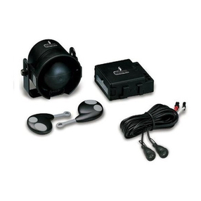
1 - LEGENDAE CONTENUTO DEL KIT / LEGENDAAND KIT CONTENTS
8772
Sirena autoalimentata
Siren with backup battery
Sirène autoalimentée
Sirena autoalimentada
Sirene auto-alimentada
Áõôïôñïöïäïôïýìåíç óåéñÞíá
Siréna s nezávislým napájením
Självförsörjande sirén
Sirene med selvmatingsbatteri
Sirene med batteri
Sirene mit back up Batterie
Sacchetto accessori
Fittings bag
Sachet des accessoires
Bolsa de accesorios
Saco de acessórios
Óáêßäéï ìå áîåóïõÜñ
Sáèek pøisluenstvím
Tillbehörspåse
Pakke med monteringsdeler
Pose med tilbehør
Zubehör
Cablaggio
Wiring harness
Câblage
Cableado
Conjunto de fios
Êáëùäßùóç
Kabelá
ablar
Ledningsnett
Kabler
Leitungssatz
Pannello di controllo
Control panel
Tableau de commande
Panel de control
Painel de controlo
Ðßíáêáò åëÝã÷ïõ
Ovládací panel
ontrollpanel
Kontrollpanel
Styrepanel
Emergenc Panel
Manuale utente/installatore
User/installation manual
Manuel utilisateur/Installateur
Manual del usuario/instalador
Manual de uso/instala ão
Åã÷åéñßäéï ÷ñÞóôç
Náv d pr uivatele/instalatéra
Användar-/installattionshandbok
Brukermanual/installatørmanual
Bruger /installatørmanual
Montage und Bedienungsanleitung
Pin Code Card
Pin Code Card
Carte Code PIN
Tarjeta de código PIN
Cartão do código PIN
in code card
Karta s pin kódem
Pin code card
PIN-kodekort
Pin kode card
Pin Code Karte
Vetrofania
Warning sticker
Vitrauphanie
Calcomanía de advertencia
Aviso autocolante
Áõôïêüëëçôá ãéá ôá ôæÜìéá
Fólie na skl s up z rnìními
Varningsetikett
Advarselssticker
Advarselsmærkat
Cobra Fensteraufkleber
Staffa
Bracket
Patte de fixation
Estribo
Presilha
Âñá÷ßïíáò
Tømen
Bygel
Bøjle
Bøjle
Halter
Radiocomando
Radio controls
Radiocommande
Radiomando
Comando por rádio
Ôçëå÷åéñéóìüò
Rádi vé vládání
Fjärrkontroller
Fjernkontroller
Fjernbetjeninger
Fernbedienungen
Centralina
Central unit
Centrale
Centralita
Central
Çëåêôñïíéêüò åãêÝöáëïò
Centrální jedn tka
Styrenhet
Sentralenhet
Central
Steuergerät
Cablaggio sirena
Siren wiring harness
Câblage sirène
Cableado de sirena
Conjunto de fios da sirene
Êáëùäßùóç óåéñÞíáò
Kabelá sirény
Sirénkablar
Ledningsnett sirene
Sirenekabler
Leitungssatz Sirene
Dima di foratura
Drilling mask
Gabarit de perçage
Escantillón para perforar
Escantilhão para perfura ão
Åëáóìá ôñõðÞìáôïò
Vrtací abl na
Borrningsmall
Hullmal
Hulskabelon
Bohrschablone
Sensori ultrasuoni
Sensor transducers
Capteurs à ultrasons
Sensores a ultrasonido
Detectores de ultra-sons
ÁéóèçôÞñáò õðåñÞ÷ùí
Ultrazvuk vé snímaèe
Ultraljudssensorer
Ultralydsensorer
Ultralydsfølere
Ultraschallsensoren
Sirena non autoalimentata
Siren without backup battery
Sirène non autoalimentée
Sirena no autoalimentada
Sirene não auto-alimentada
Ìç áõôïôñïöïäïôïýìåíç óåéñÞíá
Siréna bez vlastníh napájení
Ej självförsörjande sirén
Sirene uten selvmatingsbatteri
Sirene uden batteri
Sirene ohne back up Batterie
06DE2245D OK.pmd 09/09/2008, 10.063

G100
4
www.cobra-at.com
3
3
3
3
3
3
3
3
3
3
3
3
3
3
3
3
3
3
3
AKG 198
AKG 193
ACG 196
3
3
33
3
3
3333
3
3
KIT
3
06DE2245D OK.pmd 09/09/2008, 10.064

5
G100 MANUALE UTENTE E INSTALLATORE
I
www.cobra-at.com
INCOLLARE ETICHETTA
PIN CODE
CODICE PERSONALE PIN
5CGXXXAIA
S/N 0003 050524
PIN
CODE
1122
2 - INFORMAZIONI.
Il sistema è dotato della funzione di auto apprendimento, che permette di semplificare tutte le operazioni di aggiunta o sostituzione di radiocomandi
solo con il consenso dell’utente.
Per la procedura fare riferimento al manuale pagina 27 sul sito Internet www.cobra-at.com
2.1 - Codice personale PIN.
Ogni sistema della serie G100 ha un PIN code che può essere utilizzato per il disinserimento di emergenza.
Questo è un esempio della PIN CODE CARD
(PIN CODE programmato da fabbrica):
Vi raccomandiamo di posizionare l’etichetta adesiva PIN CODE, nell’apposita PIN CODE CARD (che troverete sul
retrodella centralina).
ATTENZIONE!
Non lasciare la PIN CODE CARD in vettura.
06DE2245D OK.pmd 09/09/2008, 10.065

MANUALE UTENTE E INSTALLATORE G100
I
6
3 - INTRODUZIONE.
Questi sistemi di allarme anti - intrusione sono controllati da un radiocomando nel caso del G100. Questa tecnologia offre un elevatissimo grado
di protezione contro ogni tentativo di riproduzione del codice. Il radiocomando permette di azionare il sistema ad una distanza di 5 - 10 metri dal
veicolo.
In alcune circostanze si può verificare una riduzione della portata a causa di interferenze generate da altre fonti (es. radioamatori che operano nella
stessa banda). In caso di mancato funzionamento avvicinarsi il più possibile al veicolo. Se é prevista la chiusura dei vetri da radiocomando, vi
raccomandiamo di effettuare questa operazione restando vicini al veicolo in modo tale che questa azione si verifichi in condizioni di sicurezza.
La protezione della vostra vettura è assicurata da:
Modello
yy
yy
y
AKG 198
AKG 193
ACG 196
yy
yy
y
yy
yy
y
yy
yy
y
yy
yy
y
yy
yy
y
yy
yy
y
yy
yy
y
PROTEZIONE
ANTIAVVIAMENTO PROTEZIONE
VOLUMETRICA PROTEZIONE
PERIMETRICA PROTEZIONE
TAGLIO CAVI
yy
yy
y
06DE2245D OK.pmd 09/09/2008, 10.066

7
G100 MANUALE UTENTE E INSTALLATORE
I
4 - ELENCO FUNZIONI.
4.1 - Funzioni standard.
Di seguito sono elencate le caratteristiche funzionali principali
dell’allarme.
• Inserimento / disinserimento per mezzo dei radiocomandi a codice
dinamico.
• Protezionevolumetrica dell’abitacoloconsensore adultrasuoni che
non necessita di regolazioni della sensibilità.
• Protezioneperimetrica.Ad allarme inserito, dopo25 slasirena suona
se una porta, il cofano o il baule vengono aperti.
• LED di indicazione dello stato del sistema con funzione di memoria
avvenutiallarmi.
• Uncircuitodi sicurezza impediscel’inserimento del sistemaamotore
in moto.
• Esclusione ultrasuoni e / o di un eventuale sensore esterno.
• Disinserimento di emergenza con pin - code.
• Protezione taglio cavi.
• Comando del sistema originale di chiusura centralizzata di porte e
baule.
• Segnalazione porte / cofano / baule aperti.
• Blinker inserimento / disinserimento.
• Inserimentoautomatico sistema.
• Inserimentoautomatico antiavviamento.
• Allarmeantiavviamento.
• Antidistrazioneimmobilizzatore.
• Antidistrazioneallarme.
• Antirapinaautomatica.
• Antirapinavolontaria.
• Blocco motore antirapina controllato da sensore di movimento.
• Procedura di selezione polarità ingresso perimetrico.
4.2 - Funzionalita’dei pulsanti del radiocomando.
PulsanteA Inseriscel’allarme el’immobilizzatore,
esclude l’ingresso volumetrico e
l’ingressosensorisupplementari,attiva
l’opzione panico, consente l’accesso
alla programmazione, seleziona la
linea, aumenta il volume del buzzer
nelle tabelle di programmazione e
attiva l’opzione Car Finder.
Pulsante B Diminuisce il volume del buzzer,
disinserisce l’allarme e
l’immmobilizzatore, attiva / disattiva
lafunzione.
B
A
B
A
06DE2245D OK.pmd 09/09/2008, 10.067

MANUALE UTENTE E INSTALLATORE G100
I
8
5 - ISTRUZIONI IN BREVE.
5.1 - Inserimento.
• Premendo il pulsante “A” del radiocomando si bloccano le porte (se
il veicolo è dotato di chiusura centralizzata).
• Gli indicatori di direzione lampeggiano due volte.
• Il buzzer emette due segnali acustici (se attivato).
• Il LED si accende a luce fissa per 25 s,poi lampeggia.
• Le protezioni diventeranno attive trascorsi 25 s.
5.2 - Inserimento silenzioso.
Per eliminare momentaneamente la segnalazione acustica del buzzer
all’inserimento,premereil tasto“A”delradiocomando prima dispegnere
il quadro.Al successivo inserimento il buzzer riprenderà a funzionare.
5.3 - Disinserimento.
• Premendo il pulsante “B” del radiocomando, si
sbloccano le porte.
• Gli indicatori di direzione lampeggiano una volta.
• Il buzzer emette un segnale acustico (se attivato).
• Le protezioni si disattivano immediatamente.
• Il LED si spegne.
5.4 - Interruzione di un’allarme in corso.
Quando il sistema é in allarme é possibile disattivare la
sirena ed il lampeggio degli indicatori di direzione,
premendo una volta il pulsante “B” del radiocomando.
Questa operazione interrompe il ciclo di allarme, ma il
sistema rimane nello stato di inserito. Per disinserire
completamenteilsistema occorrepremere una seconda
volta il pulsante “B” del radiocomando.
5.5 - Disattivazione del sensore volumetrico ad ultrasuoni.
Sedesiderate inserireil sistema di protezione lasciandoi
vetri aperti o se un passeggero resta all’interno
dell’abitacolo,è possibile disattivareilsensorevolumetrico
affinché non si verifichino allarmi.
B
A
B
A
FUNZIONI RADIOCOMANDO Pulsante
APulsante
B
Inserimento
Disinserimento
Interruzione allarme
Allarme panico
Disattivazione sensore
volumetrico ultrasuoni e sensore
a iuntivo (se installato)
Car finder
B
A
B
A
06DE2245D OK.pmd 09/09/2008, 10.068

9
G100 MANUALE UTENTE E INSTALLATORE
I
1) Attivare il sistema premendo il tasto “A” del radiocomando.
2) Premere ancora il tasto “A” del radiocomando entro 25 s.
Qualorasia installatoun sensore ad iperfrequenza oantisollevamento,
èpossibileottenernel’esclusionepremendoduevolteconsecutivamente
il tasto “A” entro 25 s. Il ricevimento del segnale è confermato da un
lampeggio degli indicatori di direzione e da un segnale acustico del
buzzer (se attivato). Il sensore é stato escluso; restano attive tutte le
altreprotezioni.I sensori siriattiverannoautomaticamenteal successivo
inserimento del sistema.
5.6 - Protezione.
Conil sistema inserito,l’apertura del cofano,del bagagliaio, diunadelle
porte o il tentativo di avviamento, genera un ciclo di allarme acustico e
visivo di 30 s circa. Per i prodotti che prevedono il sensore volumetrico
verràoriginato l’allarme aseguito di intrusionenell’abitacolo.Afineciclo
il sistema resta inserito.
5.7- Memoria di allarme.
Se durante la vostra assenza si sono verificati allarmi gli indicatori di
direzione ed il buzzer, emetteranno quattro segnali anziché uno.
6 - POSIZIONAMENTO DEGLI ELEMENTI DEL SISTEMA.
6.1 - Sensore volumetrico ad ultrasuoni (se previsto).
Le testine possono essere installate sulla parte alta dei montanti del
parabrezza anteriore o del lunotto posteriore, avendo cura che non
venganocopertequandolealetteparasolesono abbassate. Determinare
il corretto orientamento delle testine durante l’esecuzione del test
funzionale del sistema. Questo allarme incorpora un sensore che non
richiede alcuna regolazione. Si adatta ad ogni tipo di vettura
indipendentementedalla volumetriadell’abitacolo.
6.2 - Pulsante cofano.
L’installazione del pulsante è indispensabile per consentire l’accesso
alleprocedurediprogrammazione dell’ allarme eall’autoapprendimento
dei radiocomandi.Ad installazione ultimata, controllare che il pulsante
sia premuto dal cofano per almeno 5mm. Controllare che il pulsante
non vada a premere su pannelli fonoassorbenti o sulla lamiera esterna
della carrozzeria, poiché questi materiali potrebbero deformarsi nel
tempo.
6.3 -Antenna.
Il posizionamento dell’antenna è fondamentale ai fini del buon
funzionamento del sistema del radiocomando.
Il cavo non deve essere tagliato, arrotolato, collegato ad altro cavo o
alla carrozzeria e deve essere mantenuto separato dal cablaggio.
Posizionare l’antenna in modo che sia distante almeno 20 mm.da parti
metalliche.
6.4 - Pannello di emergenza.
Deve essere installato sul cruscotto in modo tale che il pulsante sia
raggiungibile ed il LED visibile anche dall’utente. Infatti oltre ad avere
una funzione deterrente il pannello (LED + pulsante) viene utilizzato
duranteleoperazioni di programmazionee per quellediriconoscimento
dell’utente
.
06DE2245D OK.pmd 09/09/2008, 10.069

MANUALE UTENTE E INSTALLATORE G100
I
10
7 - COME CONFIGURARE L’INGRESSO PERIMETRIA POSITIVO.
Attivare la riga 6 della tabella delle funzioni base seguendo le
indicazionia tergo (vedi paragrafo15“ “Come programmare il sistema
G100” sul sito www.cobra - at.com).
8 - MEMORIA DI ALLARME.
Al disinserimento il sistema avvisa di un avvenuto allarme con quattro
segnali degli indicatori di direzione e del buzzer. Prestate attenzione
alle segnalazioni del LED che saranno disponibili fino al successivo
inserimento del sistema o fino a che non verrà acceso il quadro. Le
diverse segnalazioni individuano quale é stata la causa dell’allarme.
9 - CARATTERISTICHE TECNICHE DI SISTEMA.

ATTENZIONE !
Questo prodotto è configurato per soddisfare i requisiti
della Direttiva Europea per i sistemi di allarme.
L’utilizzazione dellafunzione buzzerèconsentitasoloper
i mercati extra CE. L’attivazione invalida l’omologazione.
SEGNALAZIONE
DEL LED CAUSA DELL'ALLARME
1 lampe io apertura porte,
baule
intervento del sensore
volumetrico ad ultrasuoni
3 lampe i
apertura cofano
4 lampe i tentativi di avviamento
(chiave quadro)
5 lampe i
modulo esterno scolle ato
sirena 4310 scolle ata
6 lampe i
2 lampe i
intervento in resso sensore
di velocità / sensori a iuntivi
antifurto satellitare scolle ato
non utilizzato
7 lampe i
8 lampe i
9 lampe i
10 lampe i
non utilizzato
CARATTERISTICHE TECNICHE DEL SISTEMA
Tensione di alimentazione nominale
Tensione di esercizio 9 / 16 VDC
< 13 mA
< 15 mA
12 VDC
- 40 / +85 °C
- 40 / +105 °C
> 118 dB(A) a 1 m
> 115 dB(A) a 1 m
Consumo per confi urazione standard
(allarme con sensore ultrasuoni, arresto motore e LED 12 VDC)
- disinserito
- inserito
Temperatura d'esercizio centrale
Temperatura d'esercizio sirena
Potenza acustica
- sirena
- altoparlante
DIRETTIVE EUROPEE
Direttiva della Commissione 95/56/CE dell8 Novembre 1995
Direttiva della Commissione 2006/28/EC del 6 Marzo 2006
Direttiva della Commissione 89/336/CEE del 3 Ma io 1989
06DE2245D OK.pmd 09/09/2008, 10.0610

11
G100 USER AND FITTING INSTRUCTIONS
GB
G100
DearCustomer Thankyou andcongratulations forchoosing our product. It is a technologically advanced alarm system which meets the performance
standards set by automobile manufacturers and complies with the European directives. After the system was installed, dear Customer, you were
given the radio controls (where foreseen) and the user’s manual, which also contains the product’s declaration of conformity and the relative
installation certificate.
The manual is divided into 11 parts:
Page 3 1 -LEGENDAAND KIT CONTENTS.
12 2 -INFORMATION.
13 3 -INTRODUCTION.
14 4 -LIST OF FUNCTIONS.
15 5 -SHORT INSTRUCTIONS.
16 6 -FITTING OF SYSTEM COMPONENTS.
17 7 -HOW TO CONFIGURATE POSITIVE PERIMETRICAL INPUT.
17 8 -ALARM RECORD.
17 9 - SYSTEM’S TECHNICAL CHARACTERISTICS.
88 - 113 DIAGRAMS.
194-200 GUARANTEE.
Pleaseread the manual carefully toget thefull benefit of the productpurchased. Wealsoadvise you to keep thismanual inthe same place as yourcar
documents for easy consultation when needed. If any problem arises that cannot be resolved, please contact your dealer.
06DE2245D OK.pmd 09/09/2008, 10.0611

12 USER AND FITTING INSTRUCTIONS G100
GB
2 - INFORMATION.
Thesystem is equippedwith a self- learning functionwhich makesit possible tosimplify all operationsnecessary for adding or replacing radiocontrols
but only with the user’s consent.
For the procedure make reference to the manual at page 58 on www.cobra-at.com
2.1 - Personal PIN Code.
Each G100 system has a PIN code that is used to override the system in emergencies.
This is a PIN CODE CARD sample
(PIN CODE is factory - setted):
We advise you to stick the PIN CODE adhesive label on to the PIN CODE card (which may be found on the
rear of the control unit).
WARNING !
Don’t leave the PIN CODE CARD inside the vehicle.
www.cobra-at.com
STICK ON PIN
CODE LABEL
PERSONAL PIN CODE
5CGXXXAIA
S/N 0003 050524
PIN
CODE 1122
06DE2245D OK.pmd 09/09/2008, 10.0612

13
G100 USER AND FITTING INSTRUCTIONS
GB
3 - INTRODUCTION.
These anti-intruder alarm systems are controlled in the case of the G100 by a radio control device using high-security codes. This technology
provides a very high degree of protection against any attempt to copy the code. Theradio controltransmits at a distance of 5 – 10 metres from the
vehicle.
In some circumstances the range may be shorter due to interference from other sources (e.g. radio transmitters operating on the same band).
If the radio control is not effective in the usual range, get as close to the vehicle as you can.
If radio - controlled window closing is foreseen, we advise you to stay very close to the vehicle when carrying out this operation to make sure it is
performed under safe conditions.
Your vehicle’s complete protection is assured by:
Mod.
yy
yy
y
AKG 198
AKG 193
ACG 196
yy
yy
y
yy
yy
y
yy
yy
y
yy
yy
yyy
yy
y
yy
yy
y
yy
yy
y
yy
yy
y
ENGINE LOCK
PROTECTION VOLUMETRIC
PROTECTION PERIMETRIC
PROTECTION WIRING CUT
PROTECTION
06DE2245D OK.pmd 09/09/2008, 10.0613

14 USER AND FITTING INSTRUCTIONS G100
GB
4 - FUNCTIONS LIST.
4.1 - Standard Functions list.
The following list indicates the main functional characteristics of the
alarm system.
• Arm / Disarm by means of dynamic - code radio controls.
• Volumetric protection of the vehicle’s interior by ultrasonic sensor
not requiring sensitivity adjustment.
• Perimetric protection. When the alarm is armed, after 25 s the siren
will sound if a door or the bonnet or boot are opened.
• LED indicating the system’s status with alarm - record memory
function.
• Safetycircuittoprevent the system beingarmedwhenthethe engine
is running.
• Disablement of the sensor transducer and / or external sensor.
• Emergency disarming by pin - code.
• Wire - cutting protection.
• Original centralised door and boot closing system.
• Open door / bonnet / boot signal.
• Armed / Disarmed blinker.
• Automatic system arming.
• Automatic engine cut - off activation.
• Engine cut - off alarm.
• Anti - diversion blocker.
• Anti - diverson alarm.
• Automatic anti - robbery protection.
• Voluntary anti - robbery protection.
• Anti - robbery engine lock controlled by movement sensor.
• Perimetrical input polarity selection procedure.
4.2 - Radiocontrol button functions.
ButtonA Thisbuttonarmsthe alarm and blocker
system, deactivates the volumentric
input and additional sensors input,
activates the panic option, gives
access to the programming function,
selects the line and raises the buzzer
volumein theprogramming table, and
activates the Car Finder option.
Button B Decreasesbuzzervolume,disarmsthe
alarm and the immobilizer, enables /
disables the function.
B
A
B
A
06DE2245D OK.pmd 09/09/2008, 10.0614

15
G100 USER AND FITTING INSTRUCTIONS
GB
5 - SHORT INSTRUCTIONS.
5.1 - Arming.
• Whenradiocontrolbutton “A” ispressed,the doors lock
(if the vehicle is equipped with a centralized locking
system).
• The direction lights flash twice.
• The buzzer emits two acoustic signals (if enabled).
• The LED lights up and stays on for 25 s, then flashes.
• The protection functions activate after 25 s.
5.2 - Silent arming.
Fortemporary elimination ofthe buzzer signalwhen arming thesystem,
press radiocontrol button “A” before turning off the ignition. The next
time it is armed, the buzzer will start working again.
5.3 - Disarming.
• When radiocontrol button “B” is pressed, the doors
unlock.
• The direction lights flash once.
• The buzzer emits one acoustic signal (if enabled).
• Theprotection functionsare immediately deactivated.
• The LED is switched off.
5.4 - Interrupting an alarm during the warning - signal cycle.
While the system is sounding the alarm it is possible to
deactive the siren and flashing lights by pressing radio
control button “B” once (one press). This operation
interrupts the alarm cycle, but the system stays armed.
To deactivate the system completely, it is necessary to
disarm it by pressing radiocontrol button “B” again (two
presses).
5.5 - Deactivating the ultrasonic volumetric sensor.
If you wish to activate the protection system with the
windows left open or when a passenger will be staying
inside the passenger compartment, it is possible to
deactivatethevolumetricsensorso that it willnotgenerate
any alarms.
B
A
B
A
RADIOCONTROL FUNCTIONS Button
AButton
B
Armin
Disarmin
Interrupt alarm
Panic alarm
Deactivate ultrasonic volumetric
sensor and additional sensor
(if installed)
Car finder
B
A
B
A
06DE2245D OK.pmd 09/09/2008, 10.0615

16 USER AND FITTING INSTRUCTIONS G100
GB
1) Activate the system by pressing radiocontrol button “A”.
2) Press radiocontrol button “A” again within 25 s.
If a hyperfrequency or anti - lifting sensor is installed, it is possible to
disable it by pressing button “A” twice within 25 s. The reception of the
signal is confirmed by one flash of the direction indicators and by an
acoustic signal from the buzzer (if enabled).
Thesensor has been disabled; allthe otherprotection functions remain
active. The sensors will be automatically reactivated the next time the
system is armed.
5.11 - Protection functions.
Whenthesystemisarmed,openingthebonnet/boot/doororattempting
to start the vehicle generates an acoustic and visual alarm cycle that
lasts approximately 30 s. In products that include a volumetric sensor,
the alarm will be triggered off by intrusion into the passenger
compartment.At the cycle’s end the system stays armed.
5.12 - Alarm record.
If any alarms have occurred during your absence, the direction lamps
and buzzer will emit their signals 5times instead of once.
6 - FITTING OF SYSTEM COMPONENTS.
6.1 - Ultrasonic volumetric sensor (if foreseen).
The sensor heads can be installed on the upper part of the front
windshield or back window side - columns, making sure that they are
not covered when the sun - shield flaps are lowered. Check that the
heads are correctly oriented when you perform the functional test on
the system. The type of sensor used in this alarm system does not
requireany adjustment.It issuitable forvehicles of all types regardless
of the dimensions of their passenger compartment.
6.2 - Bonnet button.
The installation of this button is indispensable to allow access to the
alarm programming and radiocontrol self - learning procedures.
When installation is completed, check that the button is pressed by the
bonnet to the extent of at least 5mm. Check that the button does not
press on the sound - absorbing panels or the outer bodywork plate -
metal,asthese materialscould beome dented with the passing oftime.
6.3 -Antenna.
Thecorrectpositioningoftheantennaisessentialfortheproperoperation
of the radiocontrol system.
The cable must not be cut, rolled up, or connected to another cable or
to the bodywork and must be kept separate from the wiring harness.
Position the antenna so that it is at least 20 mm away from metal parts.
6.4 - Emergency Panel.
To be installedon the dashboard in a positionthat alsoensures thatthe
button can be reached and the LED can be seen by the user, as in
additionto itsdeterrent function the panel (LED +button) isused during
programming operations and in the user recognition procedure.
06DE2245D OK.pmd 09/09/2008, 10.0616

17
G100 USER AND FITTING INSTRUCTIONS
GB
7 - HOW TO CONFIGURATE POSITIVE PERIMETRICAL INPUT.
Enableline6onthebasictablesfunctionfollowingthe instructions written
onthe reverse side(see paragraph15on “How toprogramme the G100
system”on www.cobra-at.com)
8 - ALARM RECORD.
When it is being disarmed, the system reports if there has been an
alarm by four acoustic and visual signals emitted by the direction
indicators and buzzer. Pay attention to the LED signals that remain
available until the next time the system is armed or until the ignition is
turned on. The signals (number of flashes) identify the cause of the
alarm.
9 - SYSTEM’S TECHNICAL CHARACTERISTICS.
WARNING ! This product is configurated to meet the requirements of
the European Directive for alarm systems. Utilisation of
the buzzer function is allowed only for markets outside
the European Community only. Activating this function
invalidates the EC Declaration of Conformity.
LED SIGNALS CAUSE OF THE ALARM
1 flash doors/boot opened
ultrasonic volumetric sensor
tri ered
3 flashes
bonnet opened
4 flashes start -up attempts
(i nition key)
5 flashes
outside module disconnected
4310 siren disconnected
6 flashes
2 flashes
speed input sensor I addiotional
sensors tri ered
satellite anti- theft disconnected
not used
7 flashes
8 flashes
9 flashes
10 flashes
not used
TECHNICAL CHARACTERISTICS OF THE S STEM
Rated power input volta e
Operatin volta e
Consumption for standard confi uration
(alarm with ultrasonic sensors, en ine cut-off and LED 12 VDC)
9 / 16 VDC
- disarmed
- armed
< 13 mA
< 15 mA
Central operatin temperature
Siren operatin temperature
Acoustic power
12 VDC
- 40 / +85 °C
- 40 / +105 °C
> 118 dB(A) a 1 m
EUROPEAN DIRECTIVES
Commission Directive 95/56/CE of 8th November 1995
Commission Directive 2006/28/EC of 6th March 2006
Commission Directive 89/336/CEE of 3rd May 1989
- siren
> 115 dB(A) a 1 m
- loudspeaker
06DE2245D OK.pmd 09/09/2008, 10.0617

18 MANUEL UTILISATOR G100
F
G100
Cher Client,
En Vous remerciant pour le choix effectué, nous vous informons que ce produit est un système d’alarme technologiquement avancé, qui réponde
aux standards de performances définis par les constructeurs d’automobiles et qui est conforme aux directives communautaires.
Après l’installation du système, on vous a livré, cher Client, les radiotélécommandes (si prévues) et le manuel utilisateur qui contient aussi la
déclaration de conformité du produit et le certificat d’installation concerné.
Le manuel est subdivisé en 11 parties:
Page 3 1 -LÉGENDE ET KIT CONTENU.
19 2 -INFORMATION.
20 3 -INTRODUCTION.
21 4 -LISTE DES FONCTIONS.
22 5 -INSTRUCTIONS SOMMAIRES.
23 6 -ASSEMBLAGE DES COMPOSANTS DE SYSTÈME.
24 7 -COMMENT CONFIGURER L’ENTRÉE PÉRIMÉTRIQUE POSITIVE.
24 8 -MÉMOIRE D’ALARME.
24 9 -CARACTÉRISTIQUES TECHNIQUES DU SYSTÈME.
88 - 113 SCHÉMAS.
194-200 GARANTIE.
Veillez lire ce manuel avec attention: vous pourrez profiter au maximum du produit que vous venez d’acheter. Nous vous conseillons, de surcroît, de
garder ce manuel avec les papiers de la voiture pour une consultation plus aisée en cas de nécessité.
Si vous devez faire face à un problème difficile à résoudre, contactez votre vendeur.
06DE2245D OK.pmd 09/09/2008, 10.0618

19
G100 MANUEL UTILISATOR
F
www.cobra-at.com
COLLER L'ÉTIQUETTE
CODE PIN
CODE PERSONNEL PIN
5CGXXXAIA
S/N 0003 050524
CODE
PIN 1122
2 - INFORMATION.
La fonction d’auto-apprentissage dans le système, permettant d’ajouter ou de remplacer les radiotélécommandes, n’est possible qu’avec l’accord
de l’utilisateur.
Pour la procédure se rapporter au manuel page 58 sur www.cobra-at.com
2.1 - Code personnel PIN.
Chaque système G100 possède un code PIN qui est utilisé pour annuler le système en cas d’urgence.
Voici un exemple de CARTE CODE PIN
(Le CODE PIN est programmé à l’usine) :
Nous Vous recommandons de coller l’étiquette adhésive CODE PIN sur la CARTE CODE PIN (qu’est - ce que
vous trouverez à l’arrière de la centrale).
ATTENTION!
Ne pas laisser le PIN CODE CARD dans votre voiture.
06DE2245D OK.pmd 09/09/2008, 10.0619

20 MANUEL UTILISATOR G100
F
3 - INTRODUCTION.
Ces systèmes d’alarme anti-intrusion sont contrôlés par undispositif deradiotélécommande , en ce qui concerne le G100, munie de codes à haute
sécurité. Cette technologie offre un degré de protection très élevé contre toute tentative de reproduction du code. La radiotélécommande transmet
à une distance de 5- 10 mètres du véhicule
.
Dans certainescirconstances,ilpeut se vérifier une réductiondu débità cause d’interférences produites
par d’autres sources. (Ex. radioamateurs opérant dans la même bande).
En cas de non - fonctionnement, rapprochez - vous le plus possible du véhicule.
Si le verrouillage des vitres par radiotélécommande est prévu, nous vous recommandons d’effectuer cette opération en restant près du véhicule de
manière qu’elle se vérifie dans des conditions de sécurité.
La protection complète de votre véhicule est assurée par:
Modèle
yy
yy
y
AKG 198
AKG 193
ACG 196
yy
yy
y
yy
yy
y
yy
yy
y
yy
yy
yyy
yy
y
yy
yy
y
yy
yy
y
yy
yy
y
yy
yy
y
PROTECTION
ANTIDÉMARRAGE PROTECTION
VOLUMÉTRIQUE PROTECTION
COUPE CLÉS
PROTECTION
PÉRIMÉTRIQUE
06DE2245D OK.pmd 09/09/2008, 10.0620
Other manuals for G100
4
This manual suits for next models
1
Table of contents
Languages:
Other Cobra Car Alarm manuals

Cobra
Cobra 4625 User manual

Cobra
Cobra 8185 User manual

Cobra
Cobra 1046 User manual

Cobra
Cobra GLOBE 4800 CAN User manual

Cobra
Cobra SPYBALL 6808-9 User manual

Cobra
Cobra 4400 User manual

Cobra
Cobra Bridge 4100 User manual

Cobra
Cobra Connex Guardian 222X User manual

Cobra
Cobra G100 User manual

Cobra
Cobra Bridge 4100 User manual

Cobra
Cobra Connex ICD31 User manual

Cobra
Cobra G100 User manual

Cobra
Cobra BRIDGE User manual

Cobra
Cobra Vehicle Alarm Series 3100 User manual

Cobra
Cobra 3800 GLOBE User manual

Cobra
Cobra 4627 User manual

Cobra
Cobra 8510 User manual

Cobra
Cobra 3800 GLOBE User manual

Cobra
Cobra 7928 User manual

Cobra
Cobra 8510 User manual