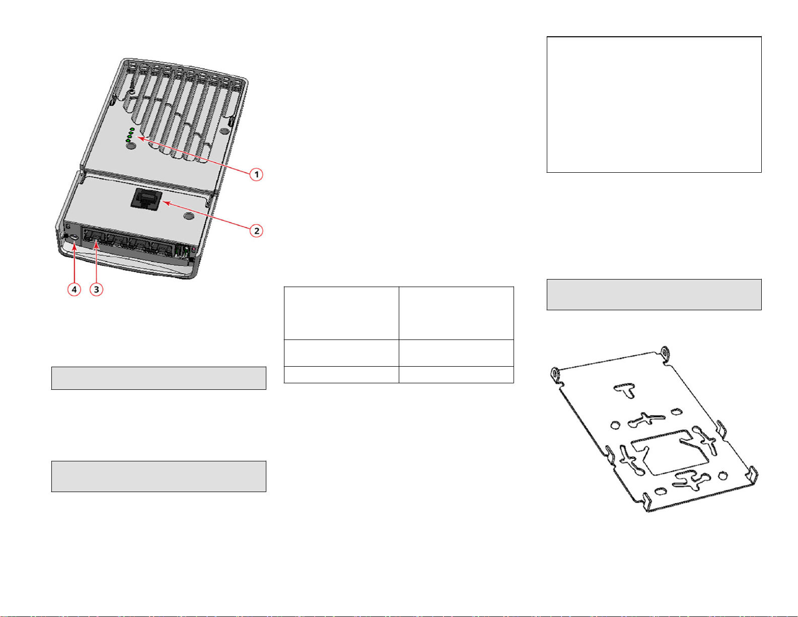
manuals.online logo
Brands
  1. Home
  2. •
  3. Brands
  4. •
  5. CommScope
  6. •
  7. Wireless Access Point
  8. •
  9. CommScope RUCKUS H550 User manual

CommScope RUCKUS H550 User manual

H550 Access Point
Quick Setup Guide
This Quick Setup Guide provides step-by-step instrucons on how to set up
your RUCKUS H550 Dual Band 802.11ax Mulmedia Wi-Fi Access Point
Wall Switch. Aer compleng the steps described in this guide, you will be
able to access the H550 Access Point Wall Switch and begin providing
wired and wireless network access to users. The rest of this document
refers to the H550 Access Point Wall Switch as the H550.
The H550 has many opons:
•It can be mounted on a standard USA- or EU-style single-gang wall
outlet box.
•It can be powered by a customer-supplied IEEE 802.3af- or 802.3at, or
IEEE 802.3bt-compliant PoE switch or injector, or can be powered by an
oponal customer-ordered DC power adapter.
•It has side slots for one or two bypass cables. The mounng bracket has
locang hooks to keep the bypass cables aligned with the slots when
aaching the H550 to the mounng base.
•It can have a 3W customer-supplied USB device plugged in. The USB
device is very dicult to remove aer the H550 is aached to the
mounng base.
NOTE: The H550 requires RUCKUS base image 104.0 rmware or later.
Managed H550 deployments require SmartZone 6.0 or later, or
ZoneDirector 10.5 or later.
About Peripheral Devices
The H550 can supply power to USB devices and PoE-powered devices, and
the power supplied depends on the PoE power supplied to the H550.
•The USB port can supply power up to a maximum of 3W. The port is
intended for customer-specic USB peripherals.
•The LAN4 + PoE Out port is intended for PoE-powered peripheral
devices such as IP telephones.
TABLE 1 H550 Power Opons and Available Power for PoE Out and USB
H550 Power Source Power available for PoE Out and
USB
802.3af PoE PoE out disabled, USB disabled
802.3at PoE 12.95 PoE Out (802.3af Class 3),
USB disabled
802.3bt Class 5 PoE or DC power
adapter
12.95 PoE Out (802.3af Class 3)
3W USB
This Guide in Other Languages
•请从以下网站获得该指南的简体中文版 hps://
support.ruckuswireless.com.
•Vous trouverez la version française de ce guide à l'adresse suivante
hps://support.ruckuswireless.com.
•このガイドの日本語版は hps://support.ruckuswireless.com でご覧
ください。
•이 가이드의 한국어 버전은 웹 사이트 (hps://
support.ruckuswireless.com) 에서 확인하시기 바랍니다.
•Veja a versão em português (Brasil) deste guia em hps://
support.ruckuswireless.com.
•Puede ver la versión en español (América Lana) de esta guía en
hps://support.ruckuswireless.com.
Before You Begin
Before deploying Ruckus products, please check for the latest soware and
the release documentaon.
•Release Notes and other user documentaon are available at hp://
support.ruckuswireless.com/documents.
•Soware upgrades are available at hp://support.ruckuswireless.com/
soware.
•Open source informaon is available at hp://
opensource.ruckuswireless.com/open_source.
Package Contents
•H550 Access Point Wall Switch
•Mounng bracket
•Two 6-mm M3x0.5 Torx at head machine screws
•Two 1-inch 6-32 Phillips pan head machine screws
•Product warranty statement
•Regulatory yer
•Declaraon of Conformity, if required
•This Quick Setup Guide
Step 1: Collecng Tools and Setup Requirements
•No. 2 Phillips screwdriver and T10 Torx driver for the mounng bracket
screws
•A standard USA- or EU-style single-gang wall outlet box
•One of the following:
–Customer-supplied IEEE 802.3af/at/bt-compliant PoE switch and
customer-supplied Ethernet cable
–Customer-supplied IEEE 802.3af/at-compliant PoE injector and
customer-supplied Ethernet cable
–Customer-ordered DC power adapter (RUCKUS part number
902-2170-XX00, sold separately)
•An Ethernet cable with or without PoE run through the wall from your
LAN through the wall outlet box
•A PC with an Ethernet port and a wireless card with customer-supplied
Cat 5e or beer Ethernet cable
•(Oponal) One or two separate bypass cables run through the outlet
box
Step 2: Connecng the PC to the H550
1. Using an Ethernet cable, connect your PC's network port to the PoE In
port on the rear of the H550.
FIGURE 1 H550 Front view
2. Using an AC adapter (sold separately), connect the H550 48V DC port
to a protected power source.
3. Verify that the PWR LED on the rear of the enclosure is green. LED
may be solid or blinking.
Copyright © 2020 CommScope, Inc. All rights reserved. Page 1 of 3
Published November 2020, Part Number 800-72461-001 Rev B
FIGURE 2 H550 Rear and boom view
1. LEDs
2. PoE In Port
3. LAN 4 + PoE Out Port
4. 48V DC Port
Step 3: Preparing Your PC for H550
1. NOTE: The following procedures assume Windows is the operang
system. Procedures for other operang systems are similar.
On your Windows PC, congure your network adapter from the Local
Area Connecon sengs: Start > Control Panel > Network and
Sharing Center > Change Adapter Sengs.
2. Edit the TCP/IPv4 address sengs: Local Area Connecons >
Properes > Internet Protocol Version 4 TCP/IPv4 > Properes.
The Internet Protocol Version 4 (TCP/IPv4) Properes dialog box is
displayed.
NOTE: Write down all of the currently acve sengs so you can
restore your PC to its current conguraon later, when this process
is complete.
3. Select Use the following IP address (if it is not already selected) and
then make the following entries:
• IP address: 192.168.0.22 (or any available address in the
192.168.0.x network, except 192.168.0.1)
• Subnet mask: 255.255.255.0
• Default gateway: 192.168.0.1
Leave the DNS server elds empty.
4. Click OK to save your changes.
Your changes are put into eect immediately.
Step 4: Logging In to the H550 Access Point
As specied in Step 3: Preparing Your PC for H550 on page 2, the H550
should be directly connected to your PC (through the PoE In port on the
back of the H550) and powered on, ready for setup.
1. On web browser window.
2. Enter https://192.168.0.1 to connect to the H550.
3. Press Enter to iniate the connecon. When a security alert dialog
box is displayed, click OK/Yes to proceed.
4. When the Ruckus Wireless Admin login page displays, enter the
following:
• Username: super
• Password: sp-admin
5. Click Login. On your rst login, you will be prompted to change the
default password.
6. When the Change Password dialog box displays, enter the following:
• New Password: Enter a new password.
•Conrm Password: Re-enter the new password.
7. Click Submit.
8. Log in using the new password.
Step 5: Customizing the Wireless Sengs
TABLE 2 Default H550 Access Point Sengs
Network Names (SSIDs) Wireless1-Wireless8 (2.4 GHz
radio)
Wireless9-Wireless16 (5 GHz
radio)
Security (Encrypon method) Disabled for each wireless
interface
Default Management IP Address 192.168.0.1
1. On the Web interface menu, click Conguraon > Radio 2.4G or
Conguraon > Radio 5G. The Congure > Wireless > Common page
is displayed.
2. Verify that the following opons are acve:
• Channel: SmartSelect
• Country Code: If you are not located in the United States of
America, select your current country.
3. Click Update Sengs if you made any changes.
4. Click any of the wireless number (Wireless LAN Number) tabs at the
top of the page.
5. In Wireless Availability, click Enabled.
6. Delete the text in the SSID eld, and enter a name for your network
that will help your users idenfy the H550 access point in their
wireless network connecon applicaons.
7. Click Update Sengs to save your changes.
8. Repeat Step 4 through Step 7 in this procedure for each wireless
number (Wireless LAN Number) interface that you want to enable.
9. Click Logout to exit the Web interface.
(Oponal): In a default H550 conguraon, the H550 uses a
DHCP-assigned IP address.
If you ancipate logging in to the H550 regularly to perform
monitoring or maintenance aer it is in place, you may want to
consider switching from DHCP and instead assigning a stac IP
address to the H550.
a. On the Web interface menu, click Conguraon >
Internet.
b. Click the Stac IP opon.
c. Enter the IP Address and Mask.
d. Click Update Sengs to save your changes.
10. When the RUCKUS Wireless Admin login page is displayed, you can
exit your browser.
11. Disconnect the H550 from the PC and the power source, and restore
your PC to its original network connecon conguraon.
Step 6: Aaching the Mounng Bracket to a Wall
Outlet Box
1. Use either the original wall outlet box screws or the factory-supplied
1-inch Phillips pan head machine screws to aach the H550 mounng
bracket to a single-gang wall outlet box.
NOTE: The H550 mounng bracket has four hooks that face up.
Make sure that the hooks are facing up when aaching the
mounng bracket to the wall outlet box.
FIGURE 3 H550 Mounng Bracket
2. Pull the LAN uplink Ethernet cable for the H550 through the wall
outlet box.
3. If you are powering the H550 with a customer-ordered 48V DC power
adapter, ensure that the power cable is able to reach the DC in port
Copyright © 2020 CommScope, Inc. All rights reserved. Page 2 of 3
Published November 2020, Part Number 800-72461-001 Rev B
without obstrucng the H550 and prevenng the H550 from
mounng ush with the wall bracket.
4. When you have extra bypass cables (usually one or two) that are to
bypass the H550, pull them through the wall outlet box.
NOTE: The bypass cables can be Ethernet, coaxial, or any other
type of cable, as required.
Drape the bypass cables across one or both of the upper hooks on
either side or both sides of the mounng bracket.
Step 7: Aaching the H550 to the Mounng
Bracket
1. Make sure that the mounng bracket is securely fastened as
described in Step 6: Aaching the Mounng Bracket to a Wall Outlet
Box on page 2.
2. If you have bypass cables (usually one or two, if any), make sure that
they are draped across one or both of the two upper hooks on the
mounng bracket.
FIGURE 4 Aaching the H550 to the Mounng Bracket
3. If you are installing a customer-supplied USB device (such as a BLE
beacon), then plug it securely into the USB jack on the boom of the
H550.
4. Pull the uplink Ethernet cable from your LAN through the outlet box,
and plug it into the back of the H550.
5. The mounng bracket has two lower hooks that t into slots on the
boom of the H550. Rest the boom of the H550 on the lower hooks,
and lt the H550 unl it is up against the mounng bracket.
NOTE: Any oponal bypass cables should slide smoothly into the
slots on the sides of the H550.
6. Use a T10 Torx driver to screw the factory-supplied Torx at head
machine screws through the H550 screw holes into the threaded
inserts on the sides of the mounng bracket.
7. Aer the H550 has powered on, depending on the power mode,
either the USB power or PoE Out may be disabled.
Step 8: Tesng the H550 Operaon
Aer a short pause to re-establish the Internet connecon, you can test
the H550.
1. Using any wireless-enabled PC or mobile device, search for and select
the wireless network you previously congured.
2. If you can connect, open a browser and navigate to any public
website.
3. Using any wired PC or other device and an Ethernet cable, plug into
an Ethernet port on the boom of the H550.
4. Open a browser and navigate to any public website.
5. Repeat Step 3 and Step 4 in this procedure for the other Ethernet
ports on the boom of the H550.
6. Verify that all connected PoE-powered devices and USB devices are
working correctly.
Congratulaons! Your H550 is acve and ready for use.
For More Informaon
For informaon, refer to hps://support.ruckuswireless.com.
Copyright © 2020 CommScope, Inc. All rights reserved. Page 3 of 3
Published November 2020, Part Number 800-72461-001 Rev B

Other CommScope Wireless Access Point manuals

CommScope Era M0201AKB_uc User manual

CommScope

CommScope Era M0201AKB_uc User manual

CommScope RUCKUS R850 User manual

CommScope

CommScope RUCKUS R850 User manual

CommScope RUCKUS Unleashed R750 User manual

CommScope

CommScope RUCKUS Unleashed R750 User manual

CommScope RUCKUS R550p User manual

CommScope

CommScope RUCKUS R550p User manual

CommScope Ruckus Unleashed R650p User manual

CommScope

CommScope Ruckus Unleashed R650p User manual

CommScope RUCKUS R350 User manual

CommScope

CommScope RUCKUS R350 User manual

CommScope RUCKUS H550 User manual

CommScope

CommScope RUCKUS H550 User manual

CommScope RUCKUS T750 User manual

CommScope

CommScope RUCKUS T750 User manual

CommScope ERA CAP M2 User manual

CommScope

CommScope ERA CAP M2 User manual

CommScope RUCKUS T350se User manual

CommScope

CommScope RUCKUS T350se User manual

CommScope SYSTIMAX InstaPATCH 360 Guide

CommScope

CommScope SYSTIMAX InstaPATCH 360 Guide

CommScope Era User manual

CommScope

CommScope Era User manual

CommScope RUCKUS E510 User manual

CommScope

CommScope RUCKUS E510 User manual

CommScope CAP MX Series User manual

CommScope

CommScope CAP MX Series User manual

CommScope T750SE User manual

CommScope

CommScope T750SE User manual

CommScope ERA CAP L2 18/21/ 23T/26 F-DC User manual

CommScope

CommScope ERA CAP L2 18/21/ 23T/26 F-DC User manual

CommScope SYSTIMAX AirSPEED AP541 User manual

CommScope

CommScope SYSTIMAX AirSPEED AP541 User manual

CommScope RUCKUS H350 User manual

CommScope

CommScope RUCKUS H350 User manual

CommScope RUCKUS Unleashed R350 User manual

CommScope

CommScope RUCKUS Unleashed R350 User manual

CommScope RUCKUS H350 User manual

CommScope

CommScope RUCKUS H350 User manual

CommScope RUCKUS Unleashed H550 User manual

CommScope

CommScope RUCKUS Unleashed H550 User manual

CommScope ERA CAP L2 18/21/ 23T/26 F-DC User manual

CommScope

CommScope ERA CAP L2 18/21/ 23T/26 F-DC User manual

CommScope RUCKUS Unleashed T350c User manual

CommScope

CommScope RUCKUS Unleashed T350c User manual

CommScope RUCRUS Q950 LTE User manual

CommScope

CommScope RUCRUS Q950 LTE User manual

Popular Wireless Access Point manuals by other brands

Atlantis Land NetFly AP1-54 quick start guide

Atlantis Land

Atlantis Land NetFly AP1-54 quick start guide

Ruijie RG-AP680-O instruction manual

Ruijie

Ruijie RG-AP680-O instruction manual

D-Link AirPremier DWL-7700AP Quick installation guide

D-Link

D-Link AirPremier DWL-7700AP Quick installation guide

Ubiquiti NBE-M5-16 quick start guide

Ubiquiti

Ubiquiti NBE-M5-16 quick start guide

Alvarion WBSIAC 3x3 Quick installation guide

Alvarion

Alvarion WBSIAC 3x3 Quick installation guide

Hamlet 300 user manual

Hamlet

Hamlet 300 user manual

LevelOne WAB-8010 Quick installation guide

LevelOne

LevelOne WAB-8010 Quick installation guide

QWNET CPE5450 Slave user manual

QWNET

QWNET CPE5450 Slave user manual

D-Link DBA-1510P Quick installation guide

D-Link

D-Link DBA-1510P Quick installation guide

TRENDnet TEW-455APBO - 9dBi High Power Wireless Outdoor PoE Access... Specifications

TRENDnet

TRENDnet TEW-455APBO - 9dBi High Power Wireless Outdoor PoE Access... Specifications

Alcatel-Lucent OAW-1200BGE Quick installation guide

Alcatel-Lucent

Alcatel-Lucent OAW-1200BGE Quick installation guide

TP-Link TL-WA801ND Setup

TP-Link

TP-Link TL-WA801ND Setup

Linksys Instant Broadband Series Fast start guide

Linksys

Linksys Instant Broadband Series Fast start guide

Honeywell WAP-PLUS Quick installation guide

Honeywell

Honeywell WAP-PLUS Quick installation guide

Gemtek Technology WLTMS-110 Quick installation guide

Gemtek Technology

Gemtek Technology WLTMS-110 Quick installation guide

EnGenius EAP-3660 user manual

EnGenius

EnGenius EAP-3660 user manual

FS AP-W6D2400C quick start guide

FS

FS AP-W6D2400C quick start guide

Alcatel Lucent 300 Series installation guide

Alcatel

Alcatel Lucent 300 Series installation guide

manuals.online logo
manuals.online logoBrands
  • About & Mission
  • Contact us
  • Privacy Policy
  • Terms and Conditions

Copyright 2025 Manuals.Online. All Rights Reserved.