manuals.online logo
Brands
  1. Home
  2. •
  3. Brands
  4. •
  5. Confer Plastics
  6. •
  7. Ladder
  8. •
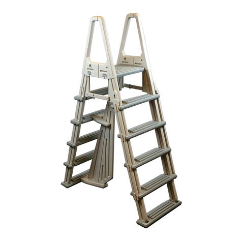
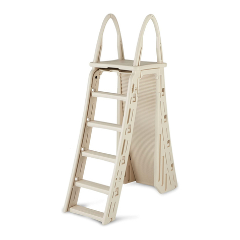
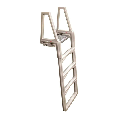
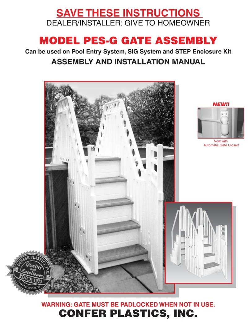
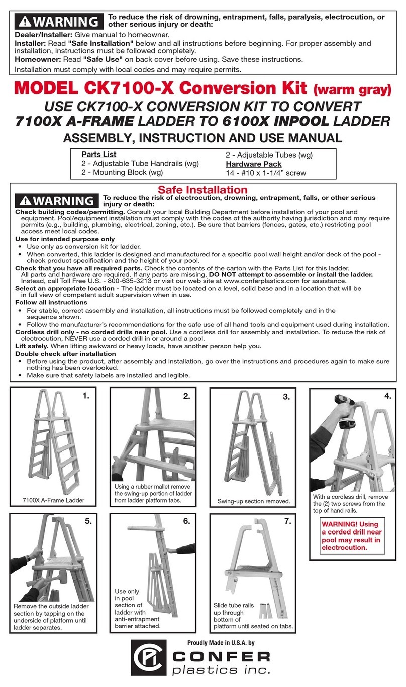
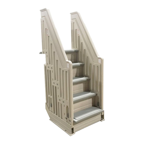
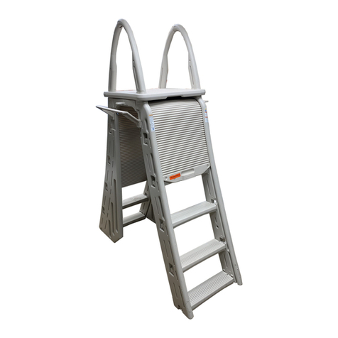
  9. Confer Plastics 6000B User guide

Confer Plastics 6000B User guide

The Anti-Entrapment Barrier is included in this ladder for the U.S. and Canada only, as required by ANSI/APSP requirements.
The Anti-Entrapment Barrier is NOT intended as a substitute for competent adult supervision.
If you would like to purchase the barrier, please visit our website at: www.conferladders.com
MADE IN THE U.S.A. by:
MODEL #6000
ADJUSTABLE HEAVY DUTY INPOOL LADDER
42" TO 56"
ASSEMBLY AND INSTRUCTION MANUAL
SAVE THESE INSTRUCTIONS
DEALER/INSTALLER: GIVE TO HOMEOWNER
IMPORTANT
FOR YOUR SAFETY
* Check the contents of the carton with the Parts list
for this ladder.
* If any parts are missing call Toll Free U.S. -
866-396-2968 or visit our web site at
www.conferladders.com
*DO NOT attempt to assemble or install the ladder
if there are ANY shortages of parts or hardware.
* For proper assembly and installation follow all
instructions in the sequence shown.
* Before using the product, after assembly and
installation, go over the instructions and procedures
again to make sure nothing has been overlooked.
* Be sure and safe. The manufacturer IS NOT
responsible for improper assembly, installation
and use.
SAFETY RULES
* One person on the ladder at a time
* Ladder MUST be installed per manufacturer’s
instructions
* DANGER: No Jumping or Diving from ladder
* Face ladder when entering and leaving pool
* To prevent entrapment or drowning — DO NOT
swim through, behind or around ladder
* Ladder to be used as a swimming pool ladder only.
* Weight limit - 350 lbs maximum
*Warning: Exceeding the maximum weight
restriction may cause the ladder to fail.
* Consult your local Building Department before
installation of your pool and equipment.
*DANGER:
Use a cordless drill for assembly
and installation. NEVER use an electric drill in
or around the pool.
SKIM-IT (SKIMS OFF DEBRIS) - Cut cleaning time 75%
with skimmer extension that guides debris directly into your
skimmer. Fits most in-ground and above-ground pool skim-
mers. Corrosion-resistant plastic Skim-It installs in seconds
without tools.
# 6000 Extension Kit (Part # 6000-EXT) - Raises ladder to
reach deck heights from 57” to approximately 68”. Kit
includes two extension boots, one additional ladder tread,
hardware and instructions.
ADDITIONALACCESSORIES MAY BE PURCHASED
Order online at
www.conferladders.com
97 Witmer Road
North Tonawanda, New York 14120-2421
Toll Free U.S. 866-396-2968
716-283-1826/ FAX 716-283-3249
www.conferladders.com
Printed in U.S.A. CP-6000 10/07
MADE IN THE U.S.A. by:
4
CONFER PLASTICS, INC.
LIMITED, PRO-RATED WARRANTY
Confer Plastics, Inc. warrants their swimming pool ladders to be free from defects in workmanship for one year from
date of purchase. After the first year the cost to replace a part is as follows:
MODEL #6000B
2nd Year - 20%
3rd Year - 40%
4th Year - 60%
5th Year - 80%
Plus shipping/handling
Enclose proof-of-purchase (receipts, etc.) showing date purchased, your name, address, and daytime phone number. You
will be notified of cost to replace part.
This warranty gives you specific legal rights, and you may also have other rights which may vary from state to state.
DO NOT RETURN DEFECTIVE PART TO DEALER
The defective part should be returned, postpaid, to:
Confer Plastics, Inc.
97 Witmer Road
North Tonawanda, N.Y. 14120-2421
of current parts
list price
Confer 6000_R8:Confer 6000_R1 12/5/07 1:29 PM Page 1
Step 1.
Snap stringers
into bottom tread.
If necessary lift
the two stringers
off the ground,
with the bottom
tread attached,
and drop them
firmly so that the
stringers “snap”
into the tread
pockets. The
bottom tread
should pivot
freely.
Make sure the
single row of
tread lugs are
facing forward.
Tread Lugs
Step 2.
Two sets of Lug
locations are provided.
Attach 4 upper treads
to the stringers in the
position determined by
the pool height.
Tread Lugs
Step 3.
Step 4. Using a pair of pliers twist off
the wedges that are attached
from the end of the platform
and SAVE for use in step 5.
Wedges
Protrusion
Detach
Wedges
Use upper
lugs for
50" to 54" pools.
Use lower
lugs for
42" to 48" pools.
Secure the
upper treads
by driving
#10 x 1-1/4"
screws through
the recessed,
pre-drilled holes
in the ends of
each tread as
shown. Repeat
for all 4 upper
treads.
Step 5.
Assemble the platform to
the handrails by laying
one of the handrails on a
clean hard surface. Push
the protrusion of the plat-
form into the openings of
the handrail making sure
that the legs of both
handrails are facing in the
same direction. Tap the
4 wedges (from step 4)
into the sides of the
handrails to secure the
platform to the rails.
Step 6.
If needed, coat tubes
with liquid soap or
lubricant and slip the
adjustable tubes
through the mounting
blocks all the way
down over the
protruding nubs.
Mounting Block
Adjustable tube Slide mounting
blocks over nubs
Step 7. Step 8.
Stringers
Step 9.
Step 10.
Snap Small and Large Barrier Sections into slots
on Lower Base as shown.
Step 11.
Separate sections at
the top slightly and
position Upper Brace
over Small Barrier
Section.
Next, spread the
“fingers” on the Upper
Brace into position on
the Large Barrier
Section as shown.
Step 12. Step 13.
Attach the handrails to
the ladder assembly,
making certain that the
treads face correctly.
Match
Platform
protrusions
to Handrail
openings
After platform is in
position, tap in the
supplied wedges at
the bottom of each
opening to ensure a
secure fit
Push the
adjustable tubes
with mounting
blocks into
handrails.
Fill both stringers with water to
allow the ladder to be submerged
in the pool.
Push
down
23
Hardware Pack
26- #10 x 1-1/4" screws
2 - Mounting Blocks
2 - Adjustable Tubes
Tools Needed for Assembly
* - Cordless Drill Motor
* - 1/8" Drill Bit
* - Phillips Screwdriver
or screwdriver bits
* - Pliers
* - Garden Hose
* - Liquid soap or lubricant
Barrier Parts List (if included)
(Included in Hardware Pack)
4 - #10 x 1-1/4” screws
1 - Strip of 4 Foam Pads
1 - Large Barrier Section
1 - Small Barrier Section
1 - Upper Brace
1 - Lower Base
Model #6000 Adjustable Heavy-Duty Inpool Ladder
ASSEMBLY INSTRUCTIONS - PLEASE READ BEFORE ATTEMPTING ASSEMBLY
Parts List
2 - Handrails
2 - Stringers (Legs)
4 - Upper treads
1 - Bottom tread
1 - Platform with Wedges
(See Step 4)
If missing parts call - Toll free U.S. - 866-396-2968 or www.conferladders.com
NOTE: To winterize your ladder, remove it from the pool and drain water from stringers and treads.
Step 14. Step 15.
C.
Drill a 1/8" pilot hole
through the handrail ends at
the pre-marked locations into
the stringers and repeat
this step for the adjustable
tubes and mounting blocks.
Place the ladder in
the desired position
on the deck and
slide the ladder
assembly down until
the bottom tread
meets the pool liner.
Slide the adjustable
tubes with the
mounting blocks as
needed to position
the ladder correctly
on the deck.
Make sure the
bottom tread is
flush with the
pool liner.
Ladder
Assembly.
Slide
adjustable
tubes to
position
against deck.
B. Using a
cordless drill
attach the
mounting
blocks with
eight (8)
#10 x 1-1/4"
screws.
A. Secure the handrail using
four (4) #10 x 1-1/4" screws
at the pre-marked locations
(two per handrail).
D. Secure the handrail to the
tubes using four (4) #10 x 1-1/4"
screws at the pre-marked
locations (two per handrail).
Submerge in
water and tilt to a
15° angle to allow
water to fill the
treads.
Note: Ladder
treads must fill
with water to
prevent floating
If Ladder did not include Barrier, skip steps 10 through 12. Continue to step 13.
Fingers
Large
Barrier
Screws
Foam
Pads
Small
Barrier
WEDGE
HANDRAIL
PLATFORM
ADJUSTABLE
TUBE
UPPER
TREAD
MOUNTING
BLOCK
STRINGER/
LEG
BARRIER
SECTION
BOTTOM
TREAD
Place the Base and
Brace into position,
centered, on the bottom
and fourth treads of the
ladder. Install the four
(4) #10 x 1-1/4” screws
(included in hardware
pack), on a slight angle,
first in the Upper Brace,
and then in the Lower
Base as shown. Install
the self-adhering foam
strips to the Large
Barrier Section
as shown.
Confer 6000_R8:Confer 6000_R1 12/5/07 1:29 PM Page 3
The Anti-Entrapment Barrier is included in this ladder for the U.S. and Canada only, as required by ANSI/APSP requirements.
The Anti-Entrapment Barrier is NOT intended as a substitute for competent adult supervision.
If you would like to purchase the barrier, please visit our website at: www.conferladders.com
MADE IN THE U.S.A. by:
MODEL #6000
ADJUSTABLE HEAVY DUTY INPOOL LADDER
42" TO 56"
ASSEMBLY AND INSTRUCTION MANUAL
SAVE THESE INSTRUCTIONS
DEALER/INSTALLER: GIVE TO HOMEOWNER
IMPORTANT
FOR YOUR SAFETY
* Check the contents of the carton with the Parts list
for this ladder.
* If any parts are missing call Toll Free U.S. -
866-396-2968 or visit our web site at
www.conferladders.com
*DO NOT attempt to assemble or install the ladder
if there are ANY shortages of parts or hardware.
* For proper assembly and installation follow all
instructions in the sequence shown.
* Before using the product, after assembly and
installation, go over the instructions and procedures
again to make sure nothing has been overlooked.
* Be sure and safe. The manufacturer IS NOT
responsible for improper assembly, installation
and use.
SAFETY RULES
* One person on the ladder at a time
* Ladder MUST be installed per manufacturer’s
instructions
* DANGER: No Jumping or Diving from ladder
* Face ladder when entering and leaving pool
* To prevent entrapment or drowning — DO NOT
swim through, behind or around ladder
* Ladder to be used as a swimming pool ladder only.
* Weight limit - 350 lbs maximum
*Warning: Exceeding the maximum weight
restriction may cause the ladder to fail.
* Consult your local Building Department before
installation of your pool and equipment.
*DANGER:
Use a cordless drill for assembly
and installation. NEVER use an electric drill in
or around the pool.
SKIM-IT (SKIMS OFF DEBRIS) - Cut cleaning time 75%
with skimmer extension that guides debris directly into your
skimmer. Fits most in-ground and above-ground pool skim-
mers. Corrosion-resistant plastic Skim-It installs in seconds
without tools.
# 6000 Extension Kit (Part # 6000-EXT) - Raises ladder to
reach deck heights from 57” to approximately 68”. Kit
includes two extension boots, one additional ladder tread,
hardware and instructions.
ADDITIONALACCESSORIES MAY BE PURCHASED
Order online at
www.conferladders.com
97 Witmer Road
North Tonawanda, New York 14120-2421
Toll Free U.S. 866-396-2968
716-283-1826/ FAX 716-283-3249
www.conferladders.com
Printed in U.S.A. CP-6000 10/07
MADE IN THE U.S.A. by:
4
CONFER PLASTICS, INC.
LIMITED, PRO-RATED WARRANTY
Confer Plastics, Inc. warrants their swimming pool ladders to be free from defects in workmanship for one year from
date of purchase. After the first year the cost to replace a part is as follows:
MODEL #6000B
2nd Year - 20%
3rd Year - 40%
4th Year - 60%
5th Year - 80%
Plus shipping/handling
Enclose proof-of-purchase (receipts, etc.) showing date purchased, your name, address, and daytime phone number. You
will be notified of cost to replace part.
This warranty gives you specific legal rights, and you may also have other rights which may vary from state to state.
DO NOT RETURN DEFECTIVE PART TO DEALER
The defective part should be returned, postpaid, to:
Confer Plastics, Inc.
97 Witmer Road
North Tonawanda, N.Y. 14120-2421
of current parts
list price
Confer 6000_R8:Confer 6000_R1 12/5/07 1:29 PM Page 1

This manual suits for next models

1

Other Confer Plastics Ladder manuals

Confer Plastics 635-52X Setup guide

Confer Plastics

Confer Plastics 635-52X Setup guide

Confer Plastics CK7100-X User manual

Confer Plastics

Confer Plastics CK7100-X User manual

Confer Plastics 6000X Setup guide

Confer Plastics

Confer Plastics 6000X Setup guide

Confer Plastics 8100X User manual

Confer Plastics

Confer Plastics 8100X User manual

Confer Plastics PES-G Setup guide

Confer Plastics

Confer Plastics PES-G Setup guide

Confer Plastics 8000X User manual

Confer Plastics

Confer Plastics 8000X User manual

Confer Plastics 7000 User manual

Confer Plastics

Confer Plastics 7000 User manual

Confer Plastics CCX-IG Setup guide

Confer Plastics

Confer Plastics CCX-IG Setup guide

Confer Plastics 7000X User manual

Confer Plastics

Confer Plastics 7000X User manual

Confer Plastics ROLLGUARD 7200 Setup guide

Confer Plastics

Confer Plastics ROLLGUARD 7200 Setup guide

Confer Plastics 8000 Setup guide

Confer Plastics

Confer Plastics 8000 Setup guide

Confer Plastics 8100X User manual

Confer Plastics

Confer Plastics 8100X User manual

Confer Plastics 6000 User manual

Confer Plastics

Confer Plastics 6000 User manual

Confer Plastics 7100X User manual

Confer Plastics

Confer Plastics 7100X User manual

Confer Plastics PES-1X User manual

Confer Plastics

Confer Plastics PES-1X User manual

Confer Plastics 635-52 User guide

Confer Plastics

Confer Plastics 635-52 User guide

Confer Plastics 6000 Setup guide

Confer Plastics

Confer Plastics 6000 Setup guide

Confer Plastics EVOLUTION 7100 Setup guide

Confer Plastics

Confer Plastics EVOLUTION 7100 Setup guide

Confer Plastics ROLLGUARD 7200 Setup guide

Confer Plastics

Confer Plastics ROLLGUARD 7200 Setup guide

Confer Plastics STEP-ENC User manual

Confer Plastics

Confer Plastics STEP-ENC User manual

Confer Plastics 7100X Setup guide

Confer Plastics

Confer Plastics 7100X Setup guide

Popular Ladder manuals by other brands

Centaure 451718 manual

Centaure

Centaure 451718 manual

Louisville PINNACLE Series installation instructions

Louisville

Louisville PINNACLE Series installation instructions

Roto Columbus Quadro 2 installation manual

Roto

Roto Columbus Quadro 2 installation manual

HSS Hire 937 Operating & safety guide

HSS Hire

HSS Hire 937 Operating & safety guide

Fieldmann FZZ 4001 operating instructions
Fieldmann

Fieldmann FZZ 4001 operating instructions

GÜNZBURGER STEIGTECHNIK 20206 operating instructions

GÜNZBURGER STEIGTECHNIK

GÜNZBURGER STEIGTECHNIK 20206 operating instructions

Branach TerrainMaster User instructions

Branach

Branach TerrainMaster User instructions

PURE 9300TL product manual

PURE

PURE 9300TL product manual

Power Step PSA-EX2500-FRS manual

Power Step

Power Step PSA-EX2500-FRS manual

MetalTech I-SBC Assembly instructions

MetalTech

MetalTech I-SBC Assembly instructions

Amstel A25 installation instructions

Amstel

Amstel A25 installation instructions

Leach 1298-IM-EN instruction manual

Leach

Leach 1298-IM-EN instruction manual

GIERRE PEPPina AL003 Operating and maintenance instructions

GIERRE

GIERRE PEPPina AL003 Operating and maintenance instructions

IRUDEK IruLadder instruction manual

IRUDEK

IRUDEK IruLadder instruction manual

HOMCOM B72-035 manual

HOMCOM

HOMCOM B72-035 manual

MediaShop 26571 Instructions for use

MediaShop

MediaShop 26571 Instructions for use

Misterstep TECH CE installation instructions

Misterstep

Misterstep TECH CE installation instructions

Hailo D100 TL TopLine Instructions for use

Hailo

Hailo D100 TL TopLine Instructions for use

manuals.online logo
manuals.online logoBrands
  • About & Mission
  • Contact us
  • Privacy Policy
  • Terms and Conditions

Copyright 2025 Manuals.Online. All Rights Reserved.