manuals.online logo
Brands
  1. Home
  2. •
  3. Brands
  4. •
  5. Confer Plastics
  6. •
  7. Ladder
  8. •
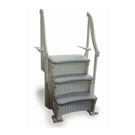
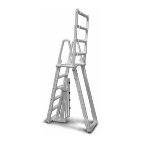
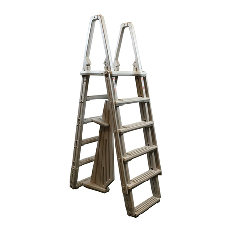
  9. Confer Plastics STEP-ENC User manual

Confer Plastics STEP-ENC User manual

CONFER PLASTICS, INC.
LIMITED, PRO-RATED WARRANTY
Confer Plastics, Inc. warrants their swimming pool ladders to be free from defects in workmanship for one year from
date of purchase. After the first year the cost to replace a part is as follows:
STEP ENCLOSURE
2nd Year - 20%
3rd Year - 40%
4th Year - 60%
5th Year - 80%
Plus shipping/handling
Enclose proof-of-purchase (receipts, etc.) showing date purchased, your name, address, and daytime phone number.
You will be notified of cost to replace part.
This warranty gives you specific legal rights, and you may also have other rights which may vary from state to state.
IMPORTANT
FOR YOUR SAFETY
• Kit MUST be installed per manufacture’s instructions
• Kit to be used with STEP-1 ONLY.
• Consult your local Building Department before installation of your pool and equipment.
• Check the contents of the product carton with the parts and hardware list.
• If any parts are missing call our toll free number:
Toll Free U.S. - 800-635-3213 or 716-694-3100
• DO NOT attempt to assemble or install the ladder if there are ANY shortages.
• For proper assembly and installation follow all instructions in the sequence
shown in this manual.
• Before using the product, after assembly and before installation, go over the
instructions and procedures again to make sure nothing has been overlooked.
• Be sure and safe. The manufacturer IS NOT responsible for improper assembly,
installation and use.
DANGER: NEVER
use an electric drill in or around the pool.
Use a cordless drill for assembly and installation
ALWAYS KEEP GATE LOCKED WHEN NOT IN USE.
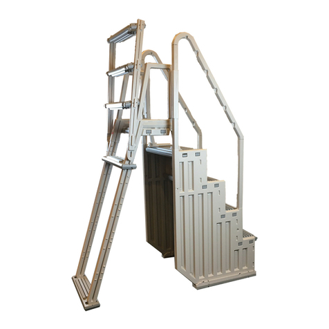
ENCLOSURE KIT
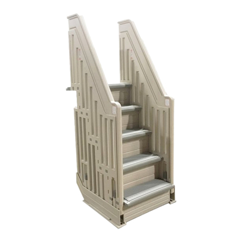
Model #STEP-ENC for Flat-Bottom, Above-Ground Pools
ASSEMBLY INSTRUCTIONS
STEP-ENC 2M 10/13
4
Made in U.S.A. by
SAVE THESE INSTRUCTIONS
DEALER/INSTALLER: GIVE TO HOMEOWNER
DO NOT RETURN DEFECTIVE PART TO DEALER
The defective part should be returned, postpaid, to:
Confer Plastics, Inc.
97 Witmer Road
North Tonawanda, N.Y. 14120-2421
of current parts
list price
COMPLETE SYSTEM
REQUIRES:
• 2-STEP-1’S
• 1-STEP-ENC
• 1-PES-G
97 Witmer Road
North Tonawanda, New York 14120-2421
Toll Free U.S./CANADA 800-635-3213
716-694-3100
ww.conferladders.com
Printed in U.S.A.
PROUDLY MADE IN THE U.S.A. by:
prpd.RG_Confer_StepEncR2_prpd.RG_Confer_StepEnc_R4q6 10/9/13 10:24 AM Page 1
Step 2.
Lay one of the connecting
rails down on a clean, flat
surface. Push the end of the
connecting step into the
openings of the connecting
rail until fully seated. Make
sure the “tread” surface of
the step is facing up towards
the rails.
Step 1.
Using a pair of pliers twist off the locking wedges
from both ends of the conecting step and SAVE.
SAVE
Secure the
connecting step by
fully inserting the locking
wedges., saved from step #1,
between the side panel and the top surface of
both ends of each step. Tap in place with a hammer.
Step 3.
Lay the second
connecting rail down
and push the
a opposite end of the
connecting step into
the openings until
fully seated.
Step 6.
Fasten the
connector kit to
the handrail
posts using (16)
#10 x 1-1/4”
screws (eight
per side) at
each of the pre-
marked
locations.
Attach the
handrails, to
the inside
unit only, as
described in
step 11 of the
STEP-1
instructions.
Step 5.
With one of the assembled
step units at the desired
location inside the pool, and
the second unit, placed
outside the pool, slide the
assembled connector kit
down over the upper handrail
posts until it is resting on the
pool top seat. IMPORTANT:
DO NOT stand on the top
steps of the unit until fully
assembled.
Step 7.
Fasten the
pickets to the
step unit at the
pre-marked lo-
cations with
twelve #10 1-
1/4” screws.
Also, secure
the gate
adapter posts
and upper
handrail posts
in place with
#10 x 1-1/4”
screws at the
pre-marked
locations.
Step 11.
Gate
installation: see
instructions
enclosed with
gate. There are
two differences
for this
installation. For
this installation
the gate posts
slide over the
adapter posts
as shown here.
And; You must
also fasten the
lowest corner of
that flange to
the step unit as
shown (see photo at far right). NOTE: the
hinge post must be on your right-hand side
(as you are looking up the steps).
Step 12.
IMPORTANT: Fasten the
lowest corner of each flange to
the step as shown below.
3
2
Align one of the triple pickets into the notches of the handrail at the top of the unit. Fasten the pickets in place, at the top of the
pickets, using the #10 x 3/4” screws. Continue placing and fastening the double pickets and then the single picket. Repeat for
the opposite handrail. Cover the ends of the screws with the protective caps.
Step 10.
Slide the gate
adapter posts
down over
the short
handrail posts
of the outside
unit until they
bottom out.
Step 8.
Step 8.
Insert the ends of
the notched
handrails into the
open ends of the
posts on the
outside unit.
Fasten in place
using four #10 x
1-1/4” screws.
Step 9.
Step 9.
Step 4.
Step 4.
ASSEMBLY INSTRUCTIONS
ENCLOSURE KIT MODEL #STEP-ENC (complete kit consists of two cartons)
PARTS LIST
Qty. Description (Carton 1 of 2)
1 Connecting Step
2 Connecting Rail
2 Gate Adapter Post
2 Set of Pickets (single, double, triple)
The following parts are supplied
in the gate carton:
(Carton 2 of 2)
1 Gate Installation Manual
2 Gate w/hardware & padlock
1 Hinge Mounting Post
1 Latch Mounting Post
HARDWARE
Qty. Description
40 #10x1-1/4” Screw
12 #10 x 3/4” Screw
12 Protective Cap
TOOLS REQUIRED FOR ASSEMBLY
• Pliers
• Mallet (or Hammer) and block of wood
• Drill Motor (cordless)
• Phillips Bit
Assemble the two STEP-1 units as per their instructions, but do not attach the mounting brackets to the
posts (as described in Step 9). These parts will not be used. Also, do not attach the handrails to
the posts (as described in Step 11 of the STEP-1 instructions).
For best installation results, the outside unit should be placed on flat patio blocks on level ground.
prpd.RG_Confer_StepEncR2_prpd.RG_Confer_StepEnc_R4q6 10/9/13 10:24 AM Page 3
CONFER PLASTICS, INC.
LIMITED, PRO-RATED WARRANTY
Confer Plastics, Inc. warrants their swimming pool ladders to be free from defects in workmanship for one year from
date of purchase. After the first year the cost to replace a part is as follows:
STEP ENCLOSURE
2nd Year - 20%
3rd Year - 40%
4th Year - 60%
5th Year - 80%
Plus shipping/handling
Enclose proof-of-purchase (receipts, etc.) showing date purchased, your name, address, and daytime phone number.
You will be notified of cost to replace part.
This warranty gives you specific legal rights, and you may also have other rights which may vary from state to state.
IMPORTANT
FOR YOUR SAFETY
• Kit MUST be installed per manufacture’s instructions
• Kit to be used with STEP-1 ONLY.
• Consult your local Building Department before installation of your pool and equipment.
• Check the contents of the product carton with the parts and hardware list.
• If any parts are missing call our toll free number:
Toll Free U.S. - 800-635-3213 or 716-694-3100
• DO NOT attempt to assemble or install the ladder if there are ANY shortages.
• For proper assembly and installation follow all instructions in the sequence
shown in this manual.
• Before using the product, after assembly and before installation, go over the
instructions and procedures again to make sure nothing has been overlooked.
• Be sure and safe. The manufacturer IS NOT responsible for improper assembly,
installation and use.
DANGER: NEVER
use an electric drill in or around the pool.
Use a cordless drill for assembly and installation
ALWAYS KEEP GATE LOCKED WHEN NOT IN USE.
ENCLOSURE KIT
Model #STEP-ENC for Flat-Bottom, Above-Ground Pools
ASSEMBLY INSTRUCTIONS
STEP-ENC 2M 10/13
4
Made in U.S.A. by
SAVE THESE INSTRUCTIONS
DEALER/INSTALLER: GIVE TO HOMEOWNER
DO NOT RETURN DEFECTIVE PART TO DEALER
The defective part should be returned, postpaid, to:
Confer Plastics, Inc.
97 Witmer Road
North Tonawanda, N.Y. 14120-2421
of current parts
list price
COMPLETE SYSTEM
REQUIRES:
• 2-STEP-1’S
• 1-STEP-ENC
• 1-PES-G
97 Witmer Road
North Tonawanda, New York 14120-2421
Toll Free U.S./CANADA 800-635-3213
716-694-3100
ww.conferladders.com
Printed in U.S.A.
PROUDLY MADE IN THE U.S.A. by:
prpd.RG_Confer_StepEncR2_prpd.RG_Confer_StepEnc_R4q6 10/9/13 10:24 AM Page 1

Other Confer Plastics Ladder manuals

Confer Plastics PES-G Setup guide

Confer Plastics

Confer Plastics PES-G Setup guide

Confer Plastics 6000 User manual

Confer Plastics

Confer Plastics 6000 User manual

Confer Plastics 6000B User guide

Confer Plastics

Confer Plastics 6000B User guide

Confer Plastics 6000X Setup guide

Confer Plastics

Confer Plastics 6000X Setup guide

Confer Plastics 8000 Setup guide

Confer Plastics

Confer Plastics 8000 Setup guide

Confer Plastics 8000X User manual

Confer Plastics

Confer Plastics 8000X User manual

Confer Plastics 7100X User manual

Confer Plastics

Confer Plastics 7100X User manual

Confer Plastics 8100X User manual

Confer Plastics

Confer Plastics 8100X User manual

Confer Plastics 635-52X Setup guide

Confer Plastics

Confer Plastics 635-52X Setup guide

Confer Plastics 7000 User manual

Confer Plastics

Confer Plastics 7000 User manual

Confer Plastics PES-1X User manual

Confer Plastics

Confer Plastics PES-1X User manual

Confer Plastics CCX-IG Setup guide

Confer Plastics

Confer Plastics CCX-IG Setup guide

Confer Plastics 8100X User manual

Confer Plastics

Confer Plastics 8100X User manual

Confer Plastics ROLLGUARD 7200 Setup guide

Confer Plastics

Confer Plastics ROLLGUARD 7200 Setup guide

Confer Plastics EVOLUTION 7100 Setup guide

Confer Plastics

Confer Plastics EVOLUTION 7100 Setup guide

Confer Plastics ROLLGUARD 7200 Setup guide

Confer Plastics

Confer Plastics ROLLGUARD 7200 Setup guide

Confer Plastics 6000 Setup guide

Confer Plastics

Confer Plastics 6000 Setup guide

Confer Plastics 7000X User manual

Confer Plastics

Confer Plastics 7000X User manual

Confer Plastics 635-52 User guide

Confer Plastics

Confer Plastics 635-52 User guide

Confer Plastics CK7100-X User manual

Confer Plastics

Confer Plastics CK7100-X User manual

Confer Plastics 7100X Setup guide

Confer Plastics

Confer Plastics 7100X Setup guide

Popular Ladder manuals by other brands

TB Davies MiniFold User's guide & instructions

TB Davies

TB Davies MiniFold User's guide & instructions

Primal Vantage MNSL-120 Instruction and safety manual

Primal Vantage

Primal Vantage MNSL-120 Instruction and safety manual

Berner TOPline 144787 Instructions for use

Berner

Berner TOPline 144787 Instructions for use

KRAUSE 842305 user manual

KRAUSE

KRAUSE 842305 user manual

Power Step PSA-773D-FS manual

Power Step

Power Step PSA-773D-FS manual

FrontLine RLA18 instruction manual

FrontLine

FrontLine RLA18 instruction manual

Powerfix Profi 282415 Operation and safety notes

Powerfix Profi

Powerfix Profi 282415 Operation and safety notes

Instant Upright Span 400 manual

Instant Upright

Instant Upright Span 400 manual

TRI-ARC VersaStep TAVSM34-AS Assembly instructions

TRI-ARC

TRI-ARC VersaStep TAVSM34-AS Assembly instructions

zarges REACHMASTER Assembly and usage instructions

zarges

zarges REACHMASTER Assembly and usage instructions

SPIETH America ST-LADDER Assembly and care instructions

SPIETH America

SPIETH America ST-LADDER Assembly and care instructions

Bestway 58337 owner's manual

Bestway

Bestway 58337 owner's manual

TB Davies EuroFold TB Davies User's guide & instructions

TB Davies

TB Davies EuroFold TB Davies User's guide & instructions

Safe Fleet PRIME DESIGN AAL-8010 Assembly instructions

Safe Fleet

Safe Fleet PRIME DESIGN AAL-8010 Assembly instructions

TRI-ARC U-DESIGN Assembly instructions

TRI-ARC

TRI-ARC U-DESIGN Assembly instructions

Vestil LAD-TRN Series instruction manual

Vestil

Vestil LAD-TRN Series instruction manual

DROMAD HIRE 500Tower instruction manual

DROMAD HIRE

DROMAD HIRE 500Tower instruction manual

Sealey LFT03.V2 instructions

Sealey

Sealey LFT03.V2 instructions

manuals.online logo
manuals.online logoBrands
  • About & Mission
  • Contact us
  • Privacy Policy
  • Terms and Conditions

Copyright 2025 Manuals.Online. All Rights Reserved.