manuals.online logo
Brands
  1. Home
  2. •
  3. Brands
  4. •
  5. Contro l4
  6. •
  7. Touch Panel
  8. •
  9. Contro l4 C4-MTSTOT3 Series User manual

Contro l4 C4-MTSTOT3 Series User manual

11
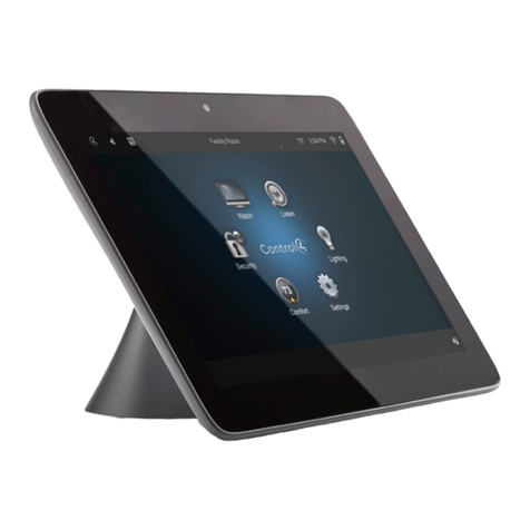
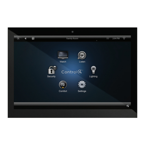
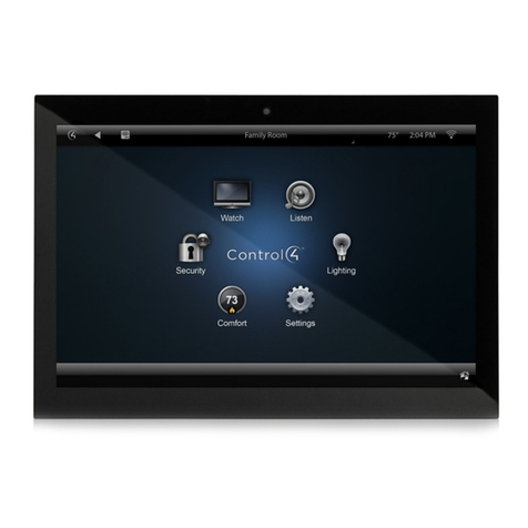
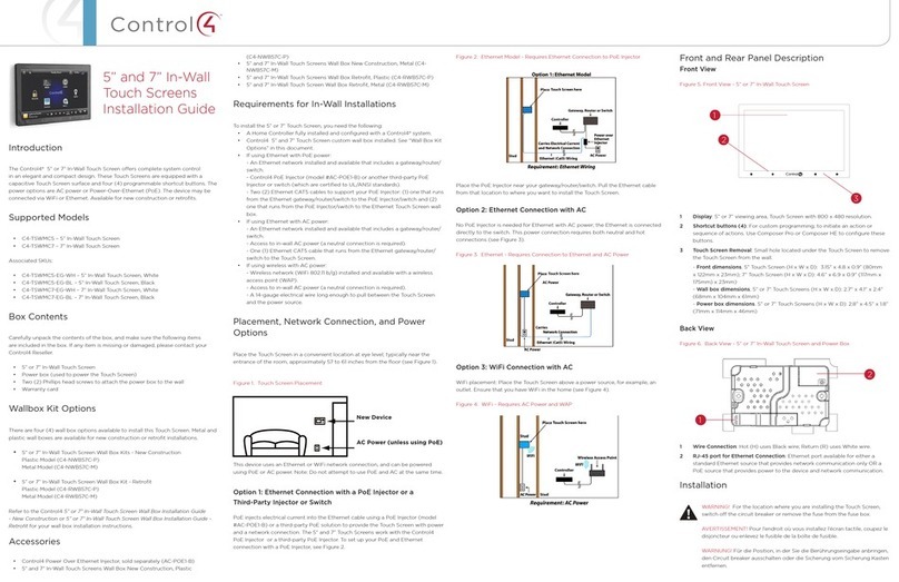
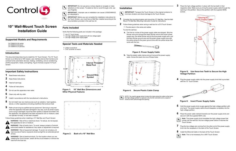
Supported touch screen models
• C4-WALL7-xx 7" In-Wall Touch Screen
• C4-WALL10-xx 10" In-Wall Touch Screen
Supported adapter kit models
• C4-MTSTOT3-xx Adapter Kit Mini Touch/LCD Keypad Back
Box to T3 Touch Screen
General description
This Control4® adapter kit provides an adapter plate to
accommodate the installation of a T3 In-Wall Touch Screen. The
kit is intended for an existing Mini Touch Screen or LCD Keypad
to be replaced by a T3 In-Wall Touch Screen.
Requirements
• Tools to modify the back box, such as a tape measure, a
pencil, a screwdriver, a small saw to cut heavy plastic, a
utility knife, or a handheld rotary cutting tool.
• A 5/16" nut driver or socket wrench, if using the metal wall
box.
What’s in the kit
• Back adapter plate
• Front adapter plate
• Two screws for power box installation
• T3 In-Wall Touch Screen Adapter Kit for Mini Touch Screen/
LCD Keypad Installation Guide (this document)
Before starting
Instead of using an adapter kit, we recommend that, wherever
possible, you entirely remove the old touch screen’s wall box,
repair the wall, then install the T3 In-Wall Touch Screen’s wall box
as designed.
Preparing for installation
Preparing the plastic wall box
1 Remove the old Mini Touch Screen/LCD Keypad and leave
the wall box in place in the wall.
2 Note the angle-shaped back box divider inside the box
(see below). You’ll need to cut a section out of this wall box
divider. Using a heavy knife or a handheld rotary cutting tool,
measure and mark 1 inch down from the front of the divider.
3 If necessary to accommodate the T3 power box, cut
vertically down so there’s a 1-inch cutout in the wall box
divider.
4 Remove the plastic piece you just cut out (see next photo).
Wall box divider
cutout
5 Go to the “Installing the adapter kit” section for more
instructions.
Preparing the metal wall box
1 Remove the old Mini Touch Screen/LCD Keypad and leave
the wall box in place in the wall (see example below).
Back box
divider
2 If necessary to accommodate the T3 power box, perform
steps 3-4. If not necessary, go to the “Installing the adapter
kit” section for more instructions.
3 Using a screwdriver, remove the screw that holds the back
box divider in place.
4 Remove the wall box divider. You’ll need this space to install
the T3 In-Wall Touch Screen power box. While you’re at it,
also remove the grounding screw from the wall box. You’ll
need this screw to move the grounding wire to your new
adapter plate.
Note: Attach the ground wire to the wall box in the
location indicated by the Ground symbol.
5 Go to the “Installing the adapter kit” section next for more
instructions.
T3 In-Wall Touch Screen
Adapter Kit for Mini Touch
Screen/LCD Keypad
Installation Guide
2
Installing the adapter kit
To attach the back adapter plate and power box:
1 Insert the grounding screw into the back of the adapter plate
(metal model). Secure the grounding wire to the grounding
screw.
2 Place the back adapter plate on top of the wall box, then
attach it to the wall box using the two screws that were used
to hold the old touch ccreen in place.
3 Insert the screws in the opposite corners of the plate (see
photo below).
Tighten this
screw first
Level the
adapter plate,
then tighten this
screw
Back plate Insert power box here
4 Follow the installation instructions in the T3 In-Wall Touch
Screen Installation Guide (
ctrl4.co/iw-ig
) to attach the AC
power or PoE connections to the power box. The use of AC
power or PoE depends on your installation requirements.
5 To attach the front adapter plate, go to “Attaching the front
adapter plate” in the next column.
Tip: If you mount the 7” touch screen with only the back
adapter plate in place, the wall box’s top and bottom
tabs may be visible. We recommend mounting a 10”
touch screen to help conceal the tabs. Alternatively, you
can mount the front adapter plate, which will conceal
the tabs at the cost of osetting the touch screen
further from the wall.
6 Insert the power box into the adapter plate, then use the
screws that came with the T3 In-Wall Touch Screen to secure
it in place.
Caution! Hand tighten the screws with very little torque.
Over-tightening the screws will drive the power box too
deep into the adapter plate and will either (1) break the
plastic tabs on the power box or (2) misalign the power
box such that the touch screen will not attach to the
power box correctly.
7 Attach the new T3 In-Wall Touch Screen to the power box.
Attaching the front adapter plate (optional)
Note: If you attach the front adapter plate, the wall box’s
top and bottom tabs will be concealed, but at the cost
of osetting the touch screen further from the wall.
To attach the front adapter plate:
1 Hold the front adapter plate over the back adapter plate.
2 Insert the power box into the adapter plate, then use the
screws that came with the T3 In-Wall Touch Screen to secure
it in place.
Caution! Hand tighten the screws with very little torque.
Over-tightening the screws will drive the power box too
deep into the adapter plate and will either (1) break the
plastic tabs on the power box or (2) misalign the power
box such that the touch screen will not attach to the
power box correctly.
3 Attach the new T3 In-Wall Touch Screen to the power box.
control4.com | 888.400.4070
Additional resources
The following resources are available for additional support:
• Control4 Knowledgebase and forums
• Control4 Technical Support
• Control4 website:
www.control4.com
• Composer documentation in online help or PDF format
available on the Dealer Portal under Support (
ctrl4.co/docs
).
Regulatory and safety information
To review regulatory information for your particular Control4
products, see the information at
ctrl4.co/reg
.
Warranty
Visit
www.control4.com/warranty
for details.
More help
For the latest version of this document, open this URL or scan
the QR code on a device that can view PDFs.
MOST RECENT VERSION
ctrl4.co/mtstot3
200-00423-A
2015-07-22 MS
Copyright ©2015, Control4 Corporation. All rights reserved. Control4, the Control4 logo, the 4-ball logo, 4Store, 4Sight, Control My Home, Everyday Easy, and
Mockupancy are registered trademarks or trademarks of Control4 Corporation in the United States and/or other countries. All other names and brands may be claimed as
the property of their respective owners. All specifications subject to change without notice. A

Other Contro l4 Touch Panel manuals

Contro l4 C4-TST7-EG-B User manual

Contro l4

Contro l4 C4-TST7-EG-B User manual

Contro l4 C4-TW7CO User manual

Contro l4

Contro l4 C4-TW7CO User manual

Contro l4 C4-TSWM10-E-A User manual

Contro l4

Contro l4 C4-TSWM10-E-A User manual

Contro l4 C4-TSWMC5-EG-WH User manual

Contro l4

Contro l4 C4-TSWMC5-EG-WH User manual

Contro l4 T3 Series User manual

Contro l4

Contro l4 T3 Series User manual

Contro l4 C4-WALL7-WH User manual

Contro l4

Contro l4 C4-WALL7-WH User manual

Contro l4 C4-TSWMC5-EG-WH User manual

Contro l4

Contro l4 C4-TSWMC5-EG-WH User manual

Contro l4 C4-TSWM10-E-W User manual

Contro l4

Contro l4 C4-TSWM10-E-W User manual

Contro l4 7 Series User manual

Contro l4

Contro l4 7 Series User manual

Contro l4 TSE-3.8C1-W User manual

Contro l4

Contro l4 TSE-3.8C1-W User manual

Contro l4 InfinityEdge User manual

Contro l4

Contro l4 InfinityEdge User manual

Contro l4 c4-tst7-eg-b User manual

Contro l4

Contro l4 c4-tst7-eg-b User manual

Contro l4 C4-TSWM7-E-B User manual

Contro l4

Contro l4 C4-TSWM7-E-B User manual

Popular Touch Panel manuals by other brands

Rosemount 751 Reference manual

Rosemount

Rosemount 751 Reference manual

BeiJer iX T15C-C23 installation manual

BeiJer

BeiJer iX T15C-C23 installation manual

Avalue Technology APC-18W9 Quick reference guide

Avalue Technology

Avalue Technology APC-18W9 Quick reference guide

i3 i3TOUCH Premium user manual

i3

i3 i3TOUCH Premium user manual

Crestron Isys TPS-5000 Field Service Guide

Crestron

Crestron Isys TPS-5000 Field Service Guide

AXIOMTEK GOT-5571TL-621 user manual

AXIOMTEK

AXIOMTEK GOT-5571TL-621 user manual

AMX MSD-1001-L quick start guide

AMX

AMX MSD-1001-L quick start guide

Alula RE667 manual

Alula

Alula RE667 manual

Zennio Z41 Firmware update

Zennio

Zennio Z41 Firmware update

Acnodes FPC-8057 Specifications

Acnodes

Acnodes FPC-8057 Specifications

IEI Technology POC-W22A-H81 Quick installation guide

IEI Technology

IEI Technology POC-W22A-H81 Quick installation guide

Zennio Touch-MyDesign Display One user manual

Zennio

Zennio Touch-MyDesign Display One user manual

IEI Technology PPC-F D-ULT5 Series user manual

IEI Technology

IEI Technology PPC-F D-ULT5 Series user manual

JHCTech ALAD-K2120T(P) user manual

JHCTech

JHCTech ALAD-K2120T(P) user manual

HEIDENHAIN ND 5023 installation instructions

HEIDENHAIN

HEIDENHAIN ND 5023 installation instructions

AMX modero NXT-CV17 Operation/reference guide

AMX

AMX modero NXT-CV17 Operation/reference guide

YASKAWA 62G-FID0 manual

YASKAWA

YASKAWA 62G-FID0 manual

syslogic TFT/HMIxxxIS6-1A Series installation guide

syslogic

syslogic TFT/HMIxxxIS6-1A Series installation guide

manuals.online logo
manuals.online logoBrands
  • About & Mission
  • Contact us
  • Privacy Policy
  • Terms and Conditions

Copyright 2025 Manuals.Online. All Rights Reserved.