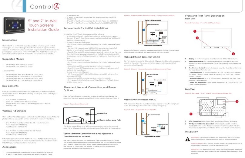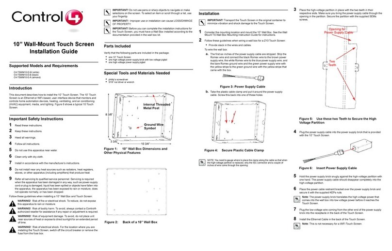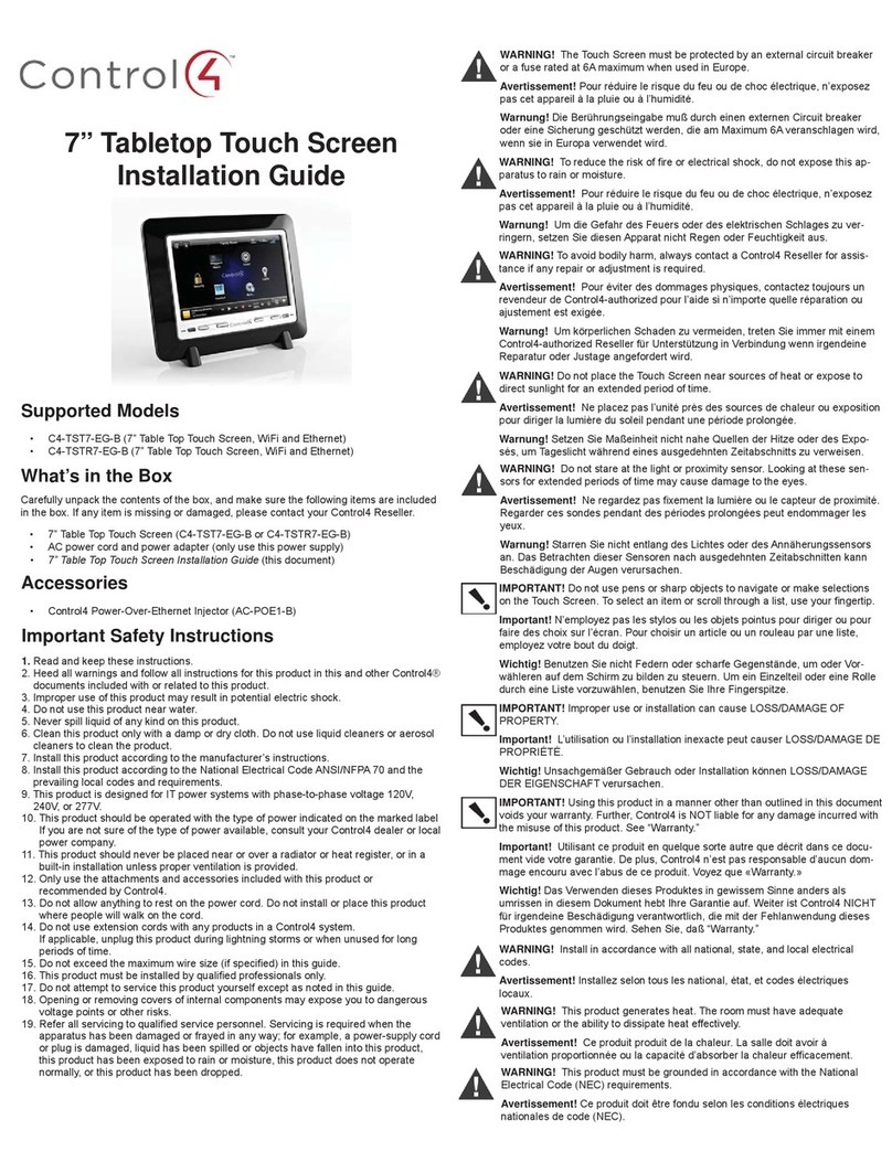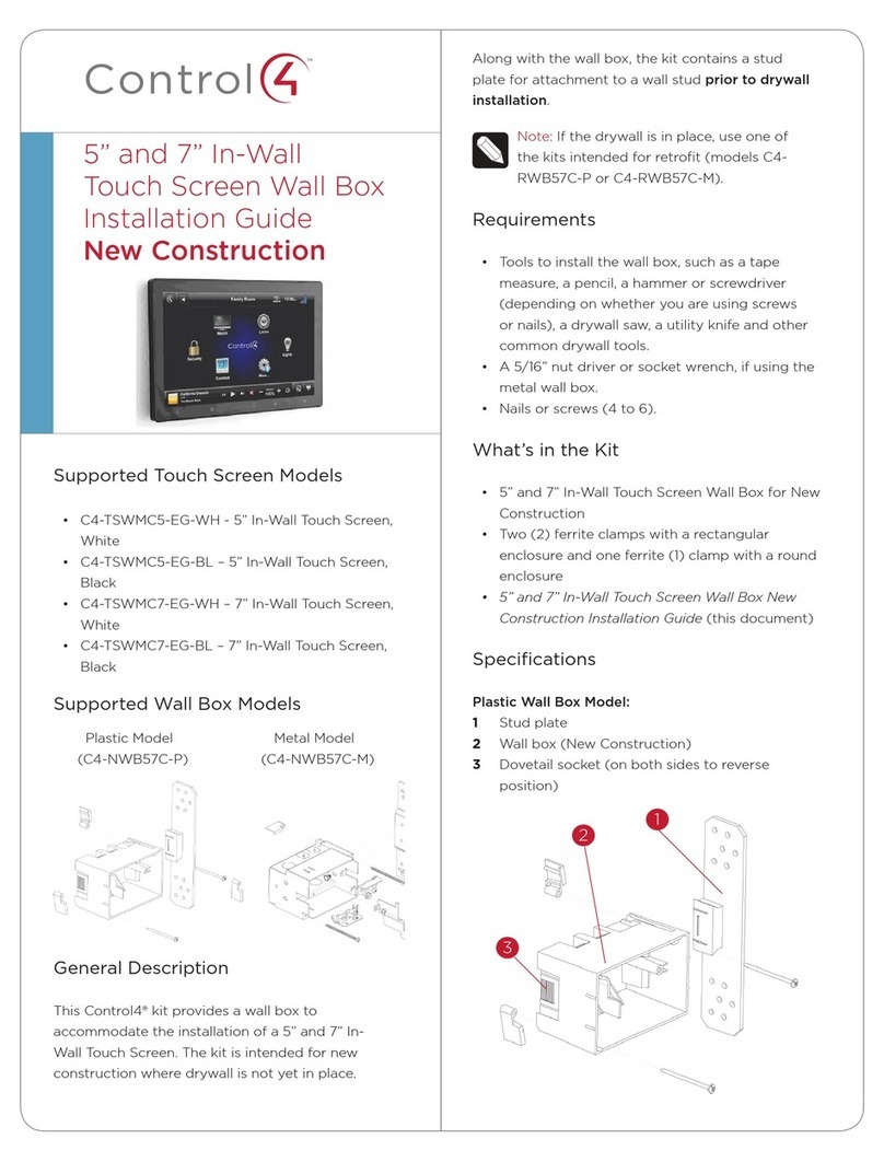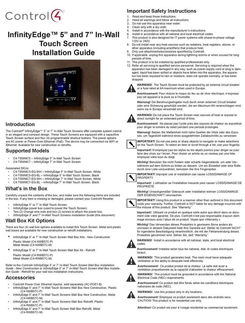
Supported Touch Screen Models
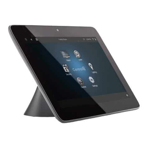
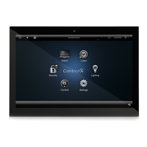
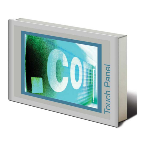
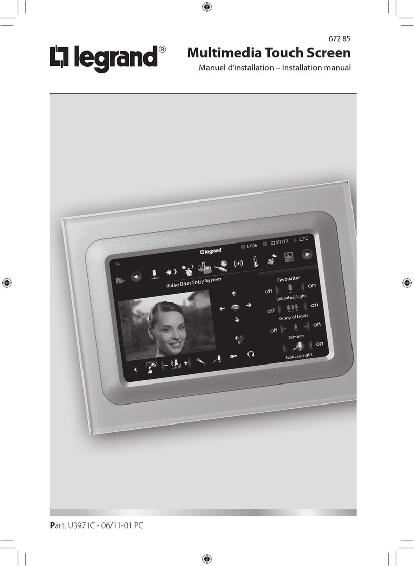
• C4-TW7CO–7”In-WallTouchScreenV2with
Camera,BlackorWhite
Supported Adapter Kit Model
• C4-7V2TOMT,BlackorWhite
General Description
ThisControl4®adapterkitprovidesametaladapter
platetoaccommodatetheinstallationofa7”In-Wall
TouchScreenV2withCamera.Thekitisintendedfor
anexistingMiniTouchScreentobereplacedbya7”
In-WallTouchScreenV2withCamera.
Requirements
• Toolstomodifythebackbox,suchasatape
measure,apencil,ascrewdriver,asmallsawto
cutheavyplastic,autilityknife,orahandheld
rotarycuttingtool.
• A5/16”nutdriverorsocketwrench,ifusingthe
metalwallbox.
What’s in the Kit
• Adapterplate
• Two(2)screwsforpowerboxinstallation
• 7”In-WallTouchScreenV2withCameraAdapter
KitforMiniTouchScreenInstallationGuide(this
document)
Specifications
Adapter Kit for a Plastic Back Box Model:
• Plasticbackbox(installedpreviously)
• Adapterplate
7”In-WallTouchScreenV2
withCamera
AdapterKitfor
MiniTouchScreen
InstallationGuide
Adapter Kit for a Metal Back Box Model:
• Metalbackbox(installedpreviously)
• Adapterplate
Prepare for Installation
Plastic Back Box Model
1 RemovetheoldMiniTouchScreenandleavethe
backboxinplaceinthewall.
2 Notetheangle-shapedbackboxdividerinside
thebox(seebelow).You’llneedtocutasection
outofthisbackboxdivider.Usingaheavyknife
orahandheldrotarycuttingtool,measureand
mark1inchdownfromthefrontofthedivider.
3 Cutverticallydownsothere’sa1-inchcutoutin
thebackboxdivider.You’llneedthisspacefor
the7”In-WallTouchScreenpowerbox.
4 Removetheplasticpieceyoujustcutout(see
photonext).
5 Gotothe‘Installation’sectionnextformore
instructions.
Metal Back Box Model:
1 RemovetheoldMiniTouchScreenandleave
thebackboxinplaceinthewall(seeexample
below).
2 Usingascrewdriver,removethescrewthatholds
thebackboxdividerinplace.
3 Removethebackboxdivider.You’llneedthis
spacetoinstallthe7”In-WallTouchScreen
powerbox.Whileyou’reatit,alsoremovethe
Back Box
Divider
Back Box Divider Cutout
