ELECTRICAL CONNECTION
1
The unit must be hooked up with the rectangular junction box already installed in
the wall.
1- Connect the ground wire (C) to the green wire (G) inside the connection box.
2- Connect the black (B) and red (R) leads from the heater to the electrical supply
wires (see diagrams below).
@V\^PSSÄUKVU[OLZ\WWS`JVYKHMV\Y[OW\YWSL^PYL7>^P[OHZLHSLKLUK
This wire must not be used for the electrical connection.This wire will be used
only if the unit is connected to a CONVECTAIR "Programmer" control system
(Contact CONVECTAIR for more informations at 1 800 463-6478 or www.
convectair.com).
4- Carefully put back all wires inside the box, close and screw the cover.
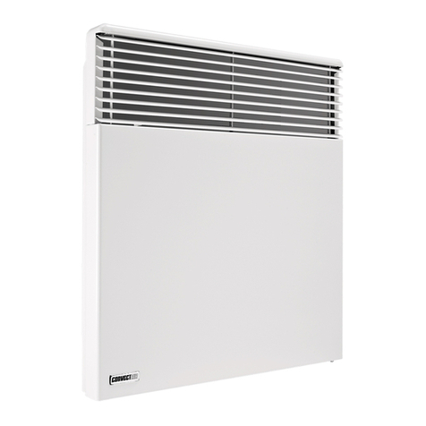
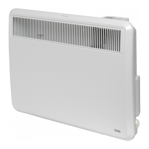
5- Hook the CONVECTAIR unit onto the mounting bracket tabs with the unit
slightly angled towards you. Push the CONVECTAIR towards the wall until it is
engaged on both locking tabs.
CAUTION : This unit must be connected to a 240 volts or 208 volts circuit, 60
cycles. Disconnect power supply before making wiring connections to prevent
electrical shock or equipment damage.
*65=,*;(09 YLJVTTLUKZ [OH[ [OPZ OLH[LY IL PUZ[HSSLK I` H X\HSPÄLK
electrician and in accordance with national and local codes.
- A rectangular junction box must be installed in the wall, prior to electrical
hookup. The box must be of appropriate size to receive the necessary electrical
connections and the 2 3/4’’ x 4 1/2’’ (70mmx115mm) cover that is supplied with
the unit cable.
- To prevent short circuits and electrical shocks turn the power off at the main
panel before attempting the installation or any repairs.
- If the power cable is damaged it must be replaced by the manufacturer, an
HWWYV]LKZLY]PJLKLWV[VYH[LJOUPJPHU^P[OZPTPSHYX\HSPÄJH[PVUZ
R
PW
R
HEATER
B
B
G
76>,9305,
C
PW
WITHOUT using
HWPSV[^PYL(PW).
B- Black G - Green R - Red
W - White C - Copper PW - Pilote Wire
R
PW
R
HEATER
B
B
G
76>,9305,
C
WITH[OL\ZLVM
HWPSV[^PYL(PW).
8
!
Please read carefully the whole installation and use ins-
tructions (*), and in particular the following

