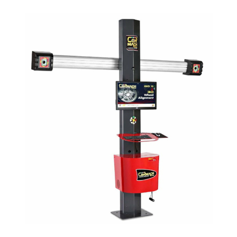
Cormach GEO 15 User manual

3D WHEEL ALIGNER
GEO 15
UK
USE AND MAINTENANCE
MANUAL
Rel. 1 03/19


3
TABLE OF CONTENTS
INTRODUCTION ��������������������������������������������������������������������������������� 5
TRANSPORT, STORAGE AND HANDLING ������������������������������������������������������ 6
AMBIENT CONDITIONS FOR MACHINE STORAGE �������������������������������������������� 6
INSTALLATION AND SET-UP �������������������������������������������������������������������� 6
AMBIENT CONDITIONS IN THE PLACE OF OPERATION ������������������������������������� 17
ELECTRICAL CONNECTIONS ������������������������������������������������������������������� 18
SAFETY REGULATIONS ������������������������������������������������������������������������� 18
KEY TO CAUTION AND INSTRUCTION LABELS ����������������������������������������������� 19
MAIN FEATURES ��������������������������������������������������������������������������������� 19
TECHNICAL DATA ������������������������������������������������������������������������������� 20
MACHINE OUTFIT ������������������������������������������������������������������������������� 20
WHAT IS AN ALIGNER? �������������������������������������������������������������������������� 20
CHARACTERISTIC ANGLES ��������������������������������������������������������������������� 21
MACHINE MAIN OPERATING PARTS ����������������������������������������������������������� 21
VEHICLE PREPARATION FOR SETTING OPERATIONS ���������������������������������������� 22
SWITCHING THE ALIGNER ON AND OFF ������������������������������������������������������ 23
GENERAL CONSIDERATIONS ������������������������������������������������������������������� 24
SCROLLING ITEMS IN A LIST ������������������������������������������������������������������� 24
MAIN SCREEN ����������������������������������������������������������������������������������� 25
OPERATING SEQUENCE SCREEN �������������������������������������������������������������� 25
ERROR SCREEN ��������������������������������������������������������������������������������� 26
VEHICLE MAKE SELECTION SCREEN ���������������������������������������������������������� 27
VEHICLE MODEL SELECTION SCREEN��������������������������������������������������������� 27
DATABANK ABBREVIATION KEY ���������������������������������������������������������������� 28
STANDARD JOB RECORD SCREEN ������������������������������������������������������������� 28
OPERATOR RECORDS SCREEN ����������������������������������������������������������������� 29
CUSTOMER RECORDS SCREEN ����������������������������������������������������������������� 29
VEHICLE RECORDS SCREEN �������������������������������������������������������������������� 30
JOB RECORDS SCREEN ������������������������������������������������������������������������� 30
DATA EDIT WINDOW ���������������������������������������������������������������������������� 31
DATA INPUT WINDOW �������������������������������������������������������������������������� 31
CHASSIS CLEARANCE SCREEN ����������������������������������������������������������������� 32
DATABANK SUMMARY SCREEN ����������������������������������������������������������������� 32
“COMPENSATION” (ROC) SCREEN ����������������������������������������������������������� 33
"PUSH MODE ROC" EXECUTION ��������������������������������������������������������������� 33
STEERING ANGLE ������������������������������������������������������������������������������� 33
REAR AXLE MEASUREMENT AND ADJUSTMENT SCREEN ������������������������������������ 34
FRONT AXLE MEASUREMENT AND ADJUSTMENT SCREEN ���������������������������������� 35
MEASUREMENT SUMMARY SCREEN ����������������������������������������������������������� 36
PERSONALISED PRINTOUT WINDOW ��������������������������������������������������������� 36
JACK & HOLD PROGRAM ���������������������������������������������������������������������� 36
SERVICE PROCEDURE SCREEN����������������������������������������������������������������� 37
UNAUTHORISED USES �������������������������������������������������������������������������� 37
MANUAL ENTERING NEW MODELS ..................................������������������������� 38

4
TROUBLESHOOTING ���������������������������������������������������������������������������� 52
MAINTENANCE ���������������������������������������������������������������������������������� 52
SCRAPPING INFO ������������������������������������������������������������������������������� 53
ENVIRONMENTAL INFORMATION �������������������������������������������������������������� 53
RECOMMENDED FIRE-EXTINGUISHING DEVICES ��������������������������������������������� 54
GLOSSARY ��������������������������������������������������������������������������������������� 54
ELECTRICAL SYSTEM DIAGRAM ��������������������������������������������������������������� 55
MOST COMMONLY ENCOUNTERED VEHICLE ALIGNMENT FAULTS ������������������������� 51
SAVING AND SEARCH JOBS CARRY OUT .............................������������������������� 44

5
INTRODUCTION
The purpose of this manual is to provide
the owner and machine operator with
effective, safe instructions for the use
and maintenance of the aligner�
If these instructions are followed carefully,
the machine will give you the efficient
and long-lasting service that has always
characterised the producer products, thus
making your work considerably easier�
The following paragraphs defi e the levels
of danger regarding the machine associ-
ated with the warning captions found in
this manual:
DANGER
Refers to immediate dangers that result
in serious injuries or even death.
WARNING
Refers to dangers or procedures that are
not totally safe and that could result in
serious injuries or even death.
CAUTION
Refers to dangers or procedures that
are not totally safe and that could result
in minor injuries or material damage.
Read these instructions carefully before
operating the machine� Keep this manual
and the illustrated materials supplied with
the equipment in a folder near the place
of operation so as to allow the machine
operators to consult the documentation
at any time�
The technical documentation supplied is
considered an integral part of the machine;
in the event of sale all relative documen-
tation must remain with the equipment�
The manual is only to be considered valid
for the machine serial number and model
stated on the attached nameplate�
WARNING
The instructions and information de-
scribed in this manual must always be
complied with: the producer shall not be
held responsible for any operation not
specifically described and authorised in
this manual.
WARNING
The wheel aligner is a measuring tool,
so the suggestions for the adjustments
to be made on the vehicle (animations
or fixed help-on-line contained in the
aligner) are merely indicative. In any
case, before making any intervention on
the vehicle, the operator must examine
and be aware of the regulations (in other
words the instructions or recommenda-
tions of the manufacturer), and always
make the adjustments in compliance
with such priority indications.
The company declines all responsibility
deriving from the execution of such
regulations and any damage that could
eventually result.
Note
Some of the illustrations contained in
this booklet were taken from pictures of
prototypes: standard production machines
may differ slightly in certain respects�
These instructions are for the attention
of persons with basic mechanical skills�
We have therefore omitted to provide
detailed instructions regarding, for exam-
ple, how to loosen or tighten the fixing
devices, etc�
Do not attempt to perform operations
unless properly qualified or with suitable
experience�
If necessary, please contact an authorised
Service Centre for assistance�
6
TRANSPORT,
STORAGE
AND HANDLING
Machine transport conditions
The aligner must be shipped in its origi-
nal packaging and stowed in the position
indicated on the outside�
Packaging data:
- Dimensions (LxWxH):
Accessories 770x1070x630 mm - weight: 95 Kg
Central unit 1300x920x560 mm - weight: 100 Kg
Camera beam 2920x240x400 mm - weight: 65 Kg
Vertical lower column 1770x200x310 - weight: 40 Kg
AMBIENT CONDITIONS
FOR MACHINE STORAGE
• Relative humidity: 20% ÷ 80%
• Temperature range: ‑10° ÷ +60°C.
WARNING
Do not stack other goods on top of the
packaging to avoid damaging it.
Handling
To move the packing, insert the forklift
tines into the slots in the base of the
packaging itself (pallet)�
To move the machine, use the trim wheels;
to lift it, insert the forklift tines under the
lower platform of the wheeled cabinet,
keeping it near the trim wheels�
CAUTION
Always use suitable hoisting belts or
tested ropes.
WARNING
This operation must be carried out very
carefully to prevent the unit from tipping
over or being damaged.
CAUTION
Handle with care: violent vibrations may
damage the equipment.
CAUTION
Keep the original packaging materials so
that the machine can be safely shipped
at a later date if necessary.
WARNING
Before moving the equipment, firs
unplug the power supply cable from its
socket.
INSTALLATION AND SET-UP
Installation clearances
WARNING
All regulations in force concerning safety
at work must be complied with when
choosing the installation position.
The ground must be sturdy enough to
bear a weight equal to the sum of the
equipment weight plus the maximum
allowed load, including the supporting
base to the ground and the specic
securing devices.
Install the aligner at the desired work
position; make sure there is at least 25
cm between the rear part of the machine
and the nearest wall.
IMPORTANT: for the correct and safe
machine operation, the lighting level
in the place of use should be at least
300 lux.

7
WARNING
The machine must not be operated in a
potentially explosive atmosphere.
CAUTION
If the machine is to be installed outdoors,
it must be properly sheltered under a
roof or any other protection device to
avoid contact with water.
CAUTION
Make sure there are no permanent mag-
nets, electromagnets or heat sources
near the machine (this might irreparably
damage the program disk and the Per-
sonal Computer).
WARNING
Take the utmost care when unpacking,
assembling, lifting and setting up the
machine as described in this heading.
Failure to observe these recommen-
dations may result in damage to the
machine and may jeopardise the opera-
tor's safety.
Installation
WARNING
Carry out the unpacking, assembly, lift-
ing and installation operations described
with care.
Failure to comply with these instructions
could damage the machine and put the
operator at risk.

You receive four boxes:
•1 box contains the two cameras and cables;
•1 box contains the two targets and other accessories;
•1 box contains the first upper column and PC holder;
•1 box contains the second lower column.
INSTALLATION AREA:Select theright height and distance asillustrated here (for 4 colum lift, please see details A).
Picture 1
Unpack the lower column (Picture 4), upper column (Picture 3) and base (Picture 2).
Picture 2 Picture 3
Picture 4
8
Details A

Assemble the lower column on the base.
Picture 5 Details 1
Mount the upper column on the lower column and fix them by two brackets (Picture 6 and Picture 7 – details 2).
Picture 6
Picture 7 Details 2
9
Bolts kit

Mount nr. 4 screws M6 x 25 on PC holder (Picture 8 – details 3).
Picture 8 Details 3
Mount the PC holder on the column and fix it with the screws (Picture 9 – details 4).
Picture 9 Details 4
Mount the monitor on the monitor holder.
Picture 10
10

Mount the monitor and the monitor holder on the column and fix it with the screws (Picture 11 – details 5).
Picture 11 Details 5
Connect the cables in to the monitor.
Picture 12
Mount and insert the keyboard holder on the column by the screws (Picture 13 – details 6). Then tighten the two
screws.
Picture 13 Details 6 Picture 14
11

Mount the mouse holder under the keyboard holder.
Picture 15 Details 7
Unpack the support plate and mount it on the column (Picture 16).
Fix the bar with the two cameras on the plate support (Picture 17).
Picture 16 Picture 17
Fix the power supply inside the PCholder by using bi-adhesive.
Picture 19
12
Picture 18

Connect the cameras supply cables intothe power supply. In detail, connect the BLUE wire into the COM and
connect the BROWN wire into the +V2.
Picture 20 Details 8
Insert the PC into the PC holder and connect the USB PLUG into the USB ports.
Picture 21Picture 22
13
TO CONNECT. The
blu and brown
cables are in
power cable

HUB: USB-HUB. Connect it to the PC.
M: Mouse
K: Keyboard
DJ: Printer
D: Display
L1-L2: Led Board to be connected to the USB HUB.
C1-C2: USB Camera to be connected directly to the PC.
P: Power cable, connect the PC to the power socket.
POW: This is the power cable to source the Led Boards. It must be connected to the power source (PS).
CM: Automatic Camera Movement Control.
POW CABLE wire
PS OUTPUT
BLUE
COM
BROWN
+12V (+V2)
L1-L2. Led board cables (with ferrites).
POW. Power cable.
C1-C2Camera cables (without ferrites).
CM: Automatic Camera MovementControl.
14
The cables shown in following pictures exit from the beam.
BLUE CABLE
BROWN CABLE

Connect all the electrical and electronic components as shown in following picture 23.
Picture 23
Mount the DRIVE-ON camera on the bottom of PC holder (Picture 24 and Picture 25) by passing the USB cable in the
proper hole.
Picture 24Picture 25
Mount the front cover on the PC holder.
Picture 26
15

To mount the printer holder, position the printer holder to the PC holder by matching the fixing holes (See Picture 27).
Picture 27
Fix the printer support with the proper screws.
Picture 28
16
Mounting printer holder (when present)

17
Software protection key
installation
Insert the software protection key supplied in
a free USB port of the USB HUB (SP, Figure
2)� The software protection key is required to
use the aligner�
CAUTION
For additional information about the
technical characteristics, warnings,
maintenance and any other data about
the monitor or the printer, read the
relative operator’s manuals supplied
with machine documentation.
Upgrading the wheel aligner
software
The wheel aligner is supplied with the
software already installed, and is com-
plete with an installation CD-ROM�
After installing the wheel aligner, switch
on the machine and go to the starting
screen�
Press the key combination È + F12 (upper
case + F12): the software version will
appear on the top left of the screen,
beneath the logo�
Compare the software release (indicated
as “SW STD …”) with that stated on the
installation CD-ROM supplied with the
aligner�
If the CD-ROM release is more recent than
the release installed, update the aligner
software�
Detailed information about the software
update procedure is provided in the leafl t
accompanying the CD-ROM�
AMBIENT CONDITIONS
IN THE PLACE OF
OPERATION
• Relative humidity: 20% ÷ 90% (without
condensation)
• Temperature range: 0°C ÷ 35°C
WARNING
The machine must not be operated in a
potentially explosive atmosphere.

18
ELECTRICAL
CONNECTIONS
The manufacturer has pre-set the aligner
to operate with a power supply of 230 VAC�
It can be pre-set to operate on 115 V AC
by setting the PC voltage shift switch
accordingly�
NOTES
- However, it is important to check that
the monitor and the printer are pre-set
to operate with voltages other than
230 V AC�
- The power supply cable supplied with
the machine complies with the regula-
tions in force�
WARNING
Any operations for connecting the
workshop electrical board must be car-
ried out only by qualified technicians
in compliance with the regulations in
force, under the responsibility and at
the charge of the customer.
• The electrical supply line must be suit-
ably sized in relation to:
1. the machine input power as specifie
on the machine data plate�
2� the distance between the machine
and the power connection point, so
that voltage drops at full load does
not exceed 4% (10% during the start‑
up phase) compared with the nominal
value of the rated voltage�
• The user must:
1. fitan electrical plug on the power sup-
ply cable in compliance with electrical
regulations in force
2�connect the machine to a suitable
power line with its own 30mA circuit
breaker
3�install protection fuses on the power
supply line, of a suitable rating accord-
ing to the indications in the general
electric diagram in this manual
4� pre-set the workshop electrical system
with an efficien protective grounding
circuit�
• In order to prevent the machine from
being used by unauthorised personnel,
it is advisable to disconnect the power
supply plug when the machine remains
idle (switched off) for long periods�
• If the machine is directly connected to the
main electrical board, without a separate
plug to socket connection, a key switch
or a switch that can be locked out must
be installed to prevent the machine from
being used by unauthorised personnel�
WARNING
A good grounding connection is essential
for correct machine operation.
NEVER connect the ground lead to a gas
or water pipe, telephone line or any other
makeshift system.
WARNING
Before connecting the power plug to the
power board make sure that the mains
voltage is the same as that indicated on
the machine data plate.
SAFETY REGULATIONS
WARNING
Failure to observe these instructions and
warnings can cause serious injuries to
operators or any other person. Do not
operate the machine until you have read
and understood all the danger/warning/
caution notices in this manual.
This machine must be used only by
qualifi d and authorised personnel.A
qualifie operator is considered to be a
person who has read and understood the
manufacturer’s instructions, is suitably
trained, and is confident with safety and
adjustment procedures to be adhered to
during operations.

19
Operators are forbidden to use the ma-
chine under the influence of alcohol or
drugs that could affect his/her physical
and mental capacity.
However, it is absolutely necessary to:
• Read and understand all instructions on
how to use the machine�
• Make sure to have a thorough knowledge
of the machine capabilities and features�
• Keep unauthorised persons well clear of
the area of operation�
• Make sure that the machine has been
installed in compliance with legislation
and standards in force�
• Make sure that all machine operators are
suitably trained, that they are capable of
using the machine correctly and that they
are adequately monitored during their
work�
• Do not touch power lines or electrical
equipment before making sure that power
has been cut off�
• Read this manual carefully and learn how
to use the machine correctly and safely�
• Always keep this user manual in a place
where it can be readily consulted when
working with the machine and consult it
whenever you are in need of confirmatio
or explanations�
WARNING
Do not remove or deface the safety
Danger, Warning or Instruction decals.
Replace any missing or illegible de-
cals. If one or more decals have been
detached or damaged, replacements
can be obtained from your nearest the
producer dealer.
• When using the machine and carrying out
maintenance on it, observe the stand-
ardised industrial accident prevention
regulations for high voltage industrial
equipment�
• Any unauthorised alterations made to the
machine automatically release the manu-
facturer from any liability in the case of
damage or accidents resulting from such
alterations. Specificall , tampering with or
removal of the machine safety devices is a
breach of the regulations relating to Safety
at work�
WARNING
Infrared Radiation!
Do not get at close range or exposed too
long to infrared radiation.
Do not observe directly with optical
instruments.
KEY TO CAUTION AND
INSTRUCTION LABELS
Unplug the power supply
cable before carrying out
maintenance/technical op-
erations on the machine�
MAIN FEATURES
Program developed on the Windows®
platform�
Angle reading with infrared CCD cameras
- 0�01 degree data display
- Databank on Hard disk or CD-ROM
- User databank and jobs archive
On-screen Help available from any point of
the program by pressing the dedicated key�
Option settings (e.g.: mm / inches, °60 /
°100, etc.) easily configured within each
program context using menus recalled by
pressing a dedicated key�
Main vehicle databank containing over
19,000 vehicles with the associated refer-
ence data for the angles�
Personalised vehicle databank, containing
the vehicles and data entered by the user
using the “insert”, “modify”, “delete”
functions�
Vehicles from the main and customised
databank displayed in a single list for easier

20
TECHNICAL DATA
‑ Measurement fields (in centesimal de-
grees):
Toe angle...........................± 48.00°
Camber or inclination............± 10.00°
Caster .............................± 30.00°
King pin ............................± 30.00°
Set back............................± 24.00°
Thrust angle......................± 24.00°
Steering angle.....................± 24.00°
• Power supply (standard) ���������������
���������������������230 V AC - 50/60 Hz
• Absorbed power...................300 W
• Power supply socket protection (mains
fuses)����������������������3�15 AT - 250 V
• Noise level in work conditions:.< 70 db(A)
MACHINE OUTFIT
- 1 CD ROM with program
- 1 CD ROM with calibration files
- 1 Steering wheel holder
- 1 Brake pedal depressor
- 1 User manual
WHAT IS AN ALIGNER?
An aligner or wheel aligner is defined as
a measurement instrument detecting the
characteristic alignment angles of a vehi-
cle (see description in the “Characteristic
angles“ chapter).
An aligner consists of a central unit and four
targets to be applied to the vehicle wheels�
WARNING
Use of the aligner for any purpose other
than its original function releases the
manufacturer from all responsibility for
any damage or injury that may result.
consultation�
Handling of reference data for adjust-
ments based on vehicle chassis height
(for vehicles which support this mode)�
Possibility of saving the job records of
the operations performed on the vehicles
(“Customer databank”)�
- LCD colour monitor
- Colour INKJET printer�
- Professional alphanumeric keyboard
- Exceptional operating freedom, the user
can shift adjustments as desired
- Steering measurement in automatic or
directly from targets
- Data can be viewed in sexagesimal, cen-
tesimal degrees, millimetres and inches�
- Graph comparison between data read
and the values in the databank
- Vehicle chassis diagnosis
- Self-centring clamp, 10” to 21”,
• Off‑centre compensation program (ROC):
• “Push- Mode ROC”
- simultaneous compensation
on the four wheels by pushing
the vehicle for a distance cor-
responding to a wheel rotation
of approximately 30°;
- applicable to 4WD vehicles�
• The adjustment windows, with different
layouts of the graphic and numeric parts�
Other manuals for GEO 15
1
Table of contents
Other Cormach Wheel Balancer manuals

Cormach
Cormach GEO 10 User manual

Cormach
Cormach TOUCH MEC 1000 SONAR Installation instructions

Cormach
Cormach GEO 15 User manual

Cormach
Cormach MEC 5 Installation instructions

Cormach
Cormach MOTO MEC User manual

Cormach
Cormach TOUCH MEC 100 User manual

Cormach
Cormach MEC 200 TRUCK User manual

Cormach
Cormach MEC 810VD-VDL-VDBL User manual

Cormach
Cormach MEC 1 Installation instructions