Corning Restricted 2
Table of Contents
1.0 Introduction........................................................................................................................................ 3
1.1 Overview........................................................................................................................................ 3
1.2 Symbols and Conventions............................................................................................................. 4
1.3 Safety Information ......................................................................................................................... 4
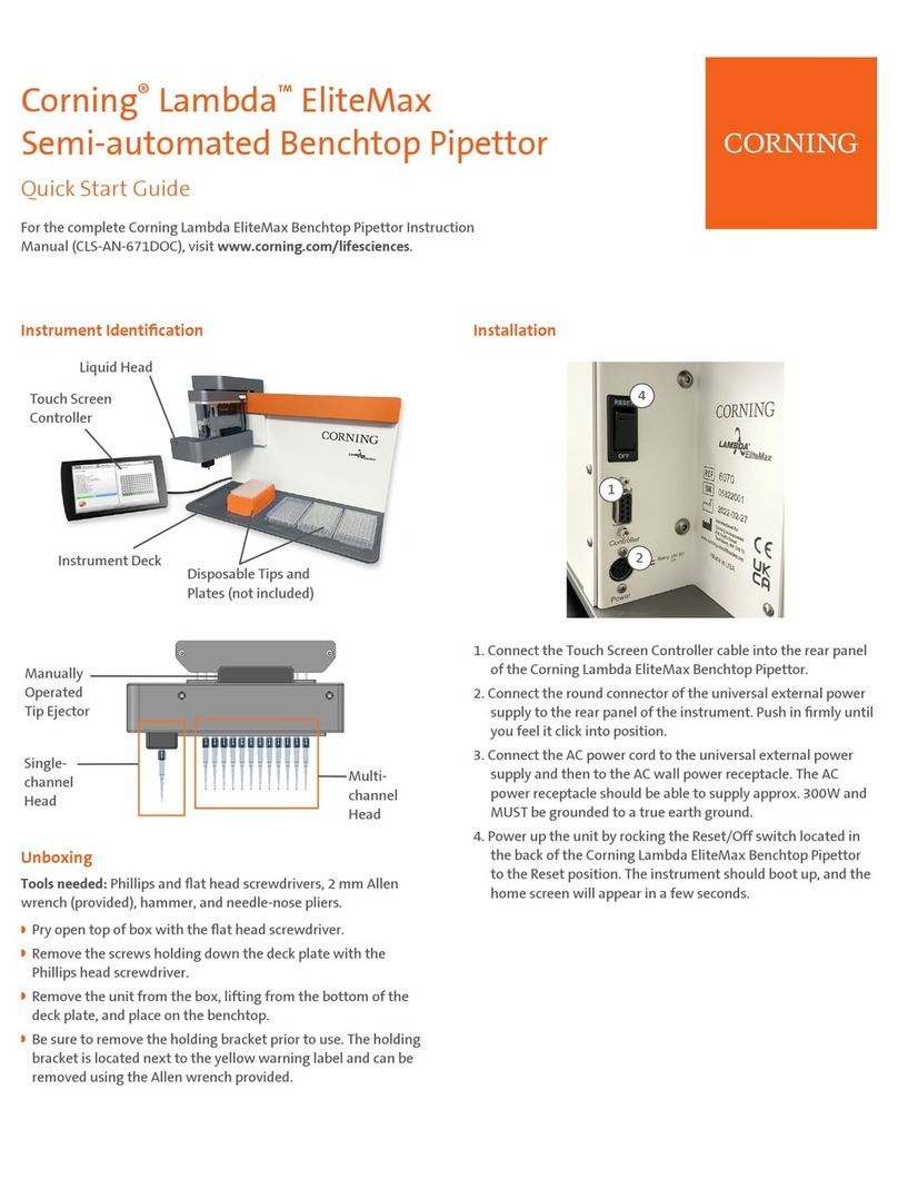
1.4 Instrument Identification ................................................................................................................ 6
1.5 Deck Positions and Orientation Convention.................................................................................. 7
1.6 Specifications ................................................................................................................................ 9
1.7 Initial Installation.......................................................................................................................... 10
1.8 Touch Screen User Interface ...................................................................................................... 10
2.0 Components Removal..................................................................................................................... 11
2.1 Liquid Head Removal.................................................................................................................. 11
2.2 Back Panel Removal................................................................................................................... 11
2.3 Front Panel Removal................................................................................................................... 13
2.4 Main Head Cover Removal ......................................................................................................... 14
2.5 Liquid Head Cover Removal ....................................................................................................... 15
2.6 Power Entry Cover Removal....................................................................................................... 16
3.0 Belts and Pulleys............................................................................................................................. 17
3.1 Up-Down Head Axis.................................................................................................................... 17
3.2 Main Axis..................................................................................................................................... 17
3.3 Single-head Axis.......................................................................................................................... 18
3.4 Liquid Head Pistons Axis............................................................................................................. 20
3.5 Linear Guideways Lubrication..................................................................................................... 20
4.0 Frame Alignment............................................................................................................................. 21
4.1 Tip Barrels Alignment.................................................................................................................. 21
4.2 Liquid Head Alignment ................................................................................................................ 21
4.3 Main Axis Alignment.................................................................................................................... 23
5.0 Electrical System............................................................................................................................. 24
5.1 Electrical Diagram ....................................................................................................................... 24
5.2 Motor Driver Board Pinout........................................................................................................... 25
5.3 Main Head Board Pinout ............................................................................................................. 26
5.4 Power Entry Module Pinout......................................................................................................... 26
5.5 AC External Power Supply.......................................................................................................... 27
5.6 Home Sensors............................................................................................................................. 27
5.7 Touch Screen Controller Pinout .................................................................................................. 28
5.8 Diagnostic and Error Codes ........................................................................................................ 29
6.0 Liquid Head Maintenance................................................................................................................ 32
6.1 Seals Replacement ..................................................................................................................... 32
6.2 Pistons Replacement................................................................................................................... 33
