2.6 Thermal Protection
¡A thermal protection circuit is built-in.
The thermal protection circuit may be activated under following
conditions and shut down the output.
1
When a current and a temperature continue to exceed the val-
ues determined by the derating curve.
2
When a fan stops or air flow weakens by intake port or exhaust
port is blocked.
If the thermal protection circuit is activated, shut off the input volt-
age and eliminate all the overheating conditions. To recover the
output voltage, have enough time to cool down the unit before
turning on the input voltage again.
2.7 Output VoltageAdjustment Range
¡To increase an output voltage, turn a built-in potentiometer clock-
wise. To decrease the output voltage, turn it counterclockwise.
¡The power supplies have an external output voltage control func-
tion. The output voltage can be adjusted within a 110% range
from 90% by changing the voltage between the terminal TRM and
the terminal COM on CN1/CN2. You can decrease the voltage by
drawing a current from the TRM terminal.
You can calculate the output voltage in this case from formula 1
below.
Please note that the formula 1gives you only an estimate.
Please contact us if you need accurate numbers.
Please do not apply negative Voltage to TRM terminal.
There is more than one method to adjust the output voltage, in-
cluding the methods to use external resistors and external power
supplies. Since each method has different characteristic, please
contact us for details.
Output voltage = Xrated output voltage---1
The voltage between
TRM and COM
2.5 [V]
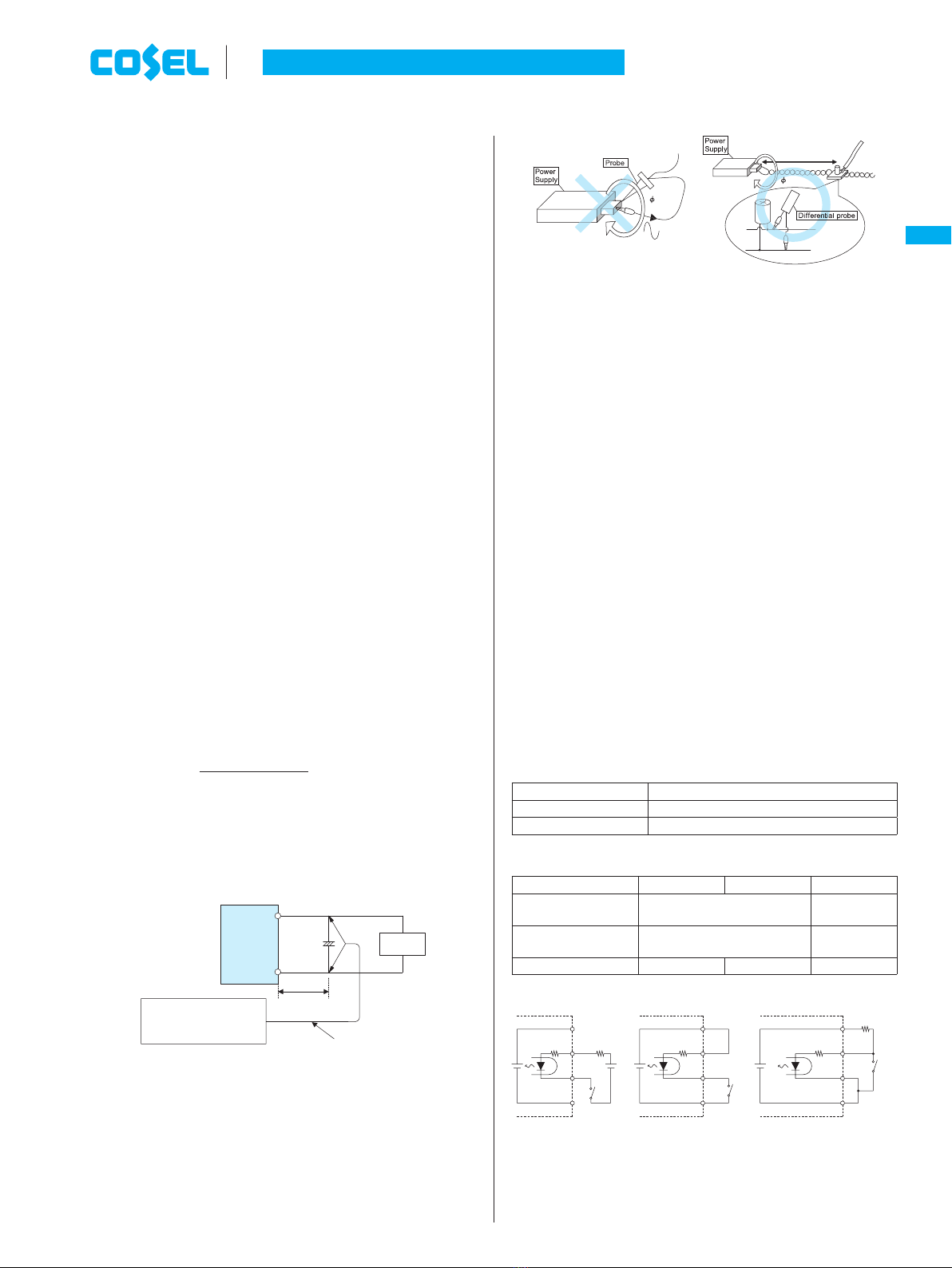
2.8 Output Ripple and Ripple Noise
¡Output ripple noise may be influenced by measurement environ-
ment, measuring method Fig.2.1 is recommended.
+Vout
-Vout
Load
150mm
C
1
Oscilloscope
Bw:500MHz
Differential probe
+
C1 : Aluminum electrolytic capacitor 22μF
Fig.2.1 Measuring method of Ripple and Ripple Noise
Remarks :
When GND cable of probe with flux of magnetic force from power
supply are crossing, ripple and ripple noise might not measure
correctly.
Please note the measuring environment.
150mm
Bad example Good example
Fig.2.2. Example of measuring output ripple and ripple noise
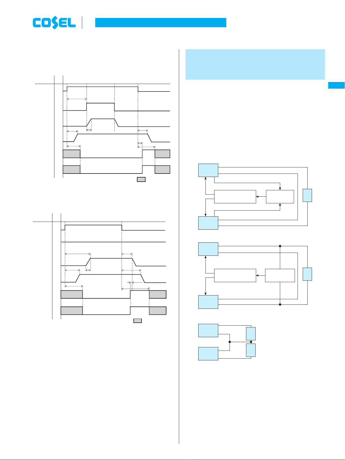
2.9 Remote ON/OFF
¡These models have a remote ON/OFF function.
¡You can operate the remote ON/OFF function by sending signals
to CN1/CN2. Please see Table 2.1 and Table 2.2 for specifica-
tions and Fig.2.3 for connecting examples.
¡Please note the followings when using the remote ON/OFF func-
tion.
1The output stops when a current flows to RC.
2The current flown to RC is a 20mA max.
3When the output voltage is turned off through the remote ON/OFF
circuit, the built-in fan slows down.
4If the output voltage is turned off through the remote ON/OFF
circuit, the WRN signals and the PG signals keep ”Low”.
5Description in this section is based on the assumption that you
will use one unit alone. If you are planning to use the units
in parallel operation or use multiple units for a single system,
please check necessary voltage and current values.
¡Please wire carefully. If you are wrongly, the internal components
of a unit may be damaged.
¡Remote ON/OFF circuits (RC and RCG) are isolated from input,
output, FG, AUX, WRN and PG.
Table 2.1 Specifications of remote ON/OFF (RC-RCG)
Output voltage Between RC and RCG
ON L level (0 to 0.5V) or open
OFF H level (4.5 to 12.5V)
Table 2.2 Specifications of remote ON/OFF (Case of Fig.2.3)
Connection method Fig.2.3 (a) Fig.2.3 (b) Fig.2.3 (c)
Power ON SW open
(0.1mA max) SW close
(0.5V max)
Power OFF SW close
(3mA min) SW open
(0.1mA max)
Base pin RCG AUXG RCG, AUXG
Ri=780WRi=780WRi=780W
RCG
RC RC RC
AUX AUX AUX
RCG
AUXG AUXG
RCG
AUXG
SW SW
SW
Rb=1kW
Vcc
Ra*1
(a) (b) (c)
12V
typ 12V
typ 12V
typ
Fig.2.3 Examples of connecting remote ON/OFF circuit
AC-DC Power Supplies Enclosed type Instruction Manual
FETA-7
FETA
mefeta1.indd7me feta1 indd 7 2013/09/0914:28:402013/09/09 14:28:40