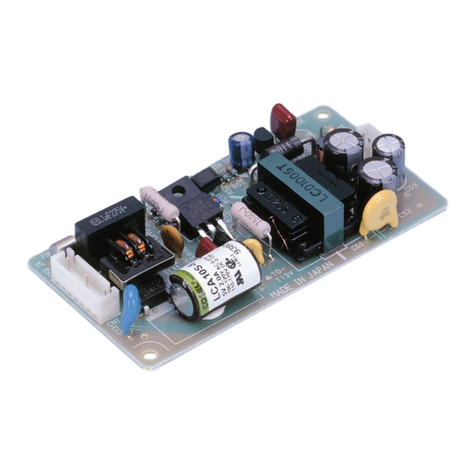
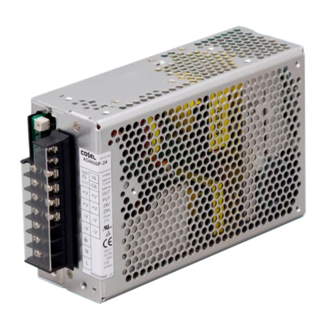
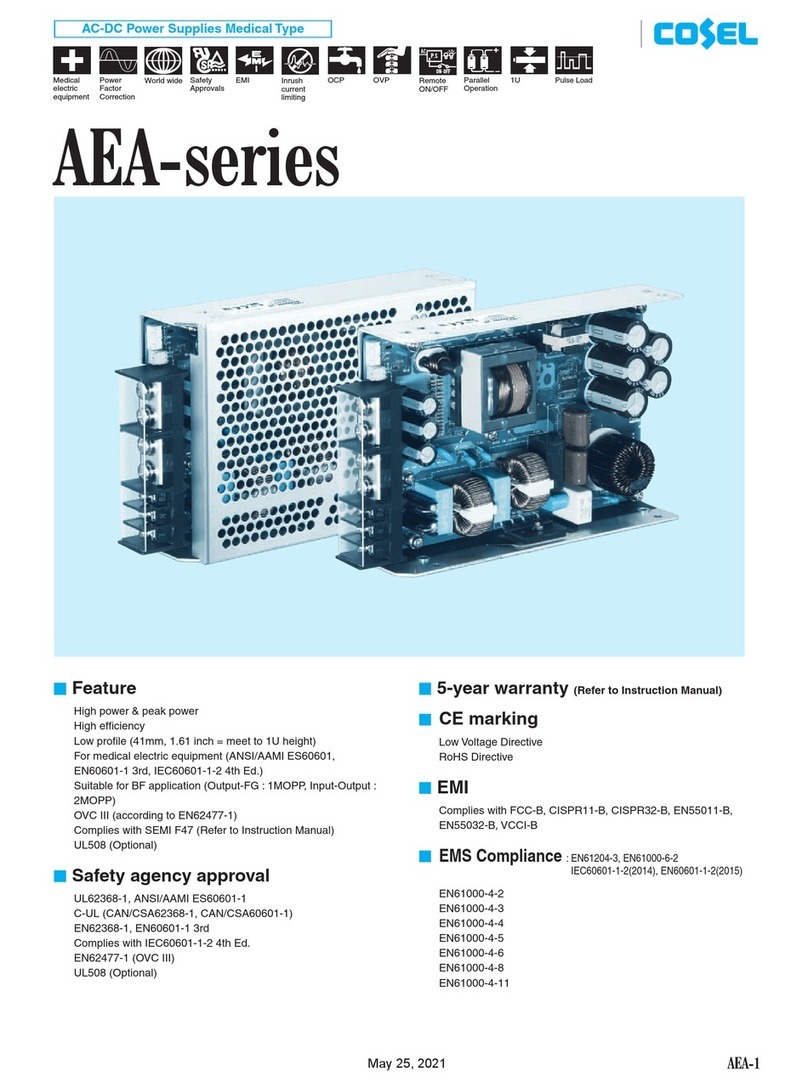
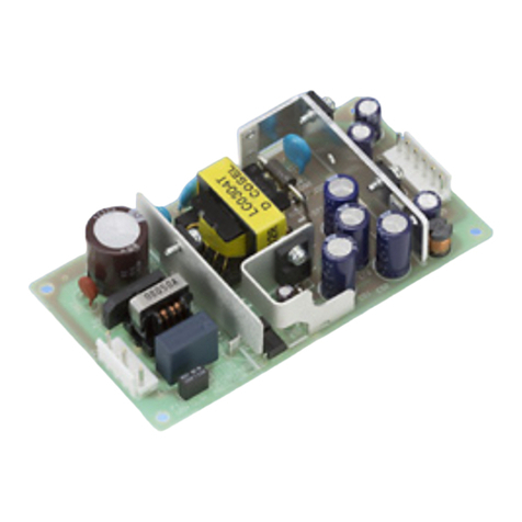
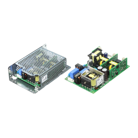
Cosel AD240 User manual

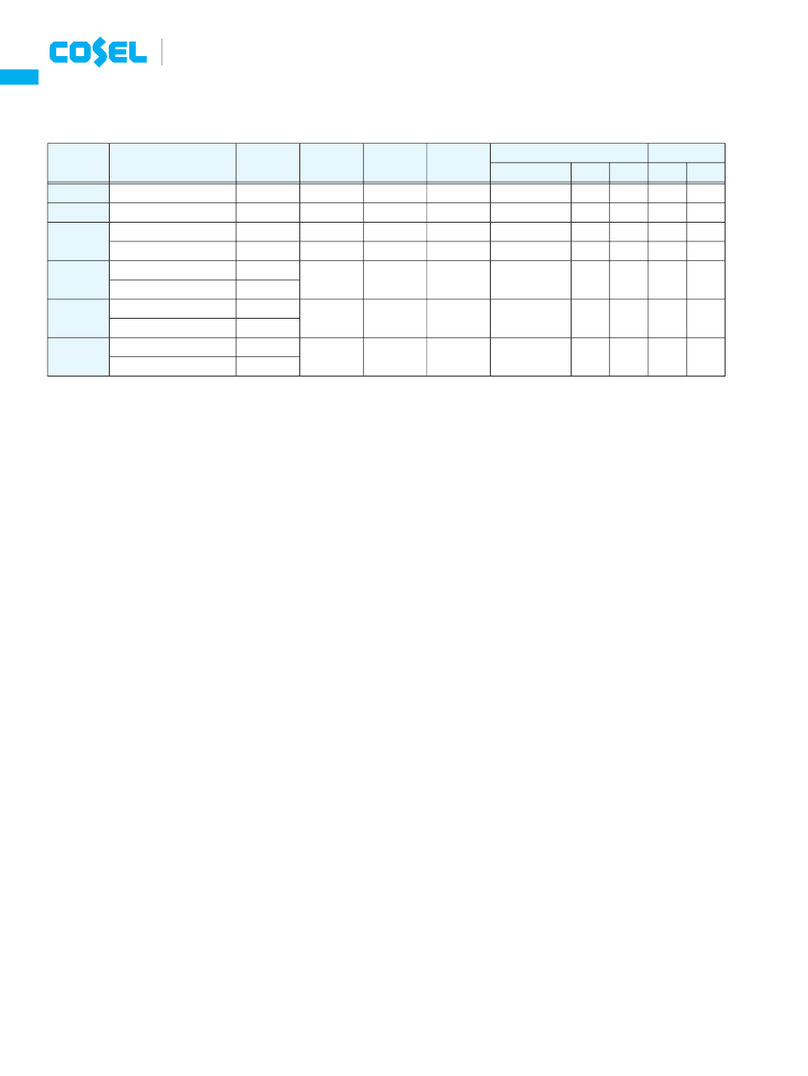
Basic Characteristics Data
*1Refer to Instruction Manual.
*The value of input current is at ACIN 100V and rated load (As for AD960, ACIN200V and rated load).
input fuse
250 20A
250 15A
250 10A
AD960
AD480
AD240
Forward converter
Forward converter
Forward converter
10.0
10.0
5.0
170
200
54
Circuit method
operation availability
*1
*1
YesTriac
Triac
Triac
FR-4
FR-4
FR-4
Yes
Yes
Yes
Yes
Yes
Yes
Rated
Basic Characteristics Data
Model
frequency
Switching
[A]
current
Input
Series/Parallel
Parallel
operation
PCB/Pattern
Inrush
protection
current
Material
Double
sidedsided
Single
Series
operation
[kHz]
AD-8
AD
June29,2011

1 Terminal Block
2 Function
3
5
Series Operation and Parallel Operation
Peak Loading
AD-9
4 Assembling and Installation Method
4.1
4.2
4.3
Instruction Manual
AD-10
AD-11
AD-14
2.1
3.1
2.2
3.2
2.3
2.4
2.5
2.6
2.7
2.8
Input voltage range
Series operation
Installation method
Inrush current limiting
Parallel operation/master-slave operation
Derating
Mounting screw
Overcurrent protection
Overvoltage protection
Output voltage adjustment range
Remote ON/OFF
Isolation
Thermal protection
AD-10
AD-10
AD-10
AD-11
AD-11
AD-11
AD-11
AD-11
AD-12
AD-12
AD-12
AD-13
AD-11
AD-11
AD-10 AD
AC-DC Power Supplies Enclosed type
June29,2011

1 Terminal Block
AD-10
lAD240
lAD960
lAD480
+Output
-Output
Frame ground
Input voltage selecting terminal
Short: AC 85 - 132V Open: AC170 - 264V
AC(L)
AC(N)
Output voltage adjustable potentiometer
Frame ground
Input voltage selecting terminal
AC(N)
AC(L)
Output voltage adjustable potentiometer
+Output
-Output
Remote ON/OFF(RC)
Remote ON/OFF(RCG)
Voltage balance(VB)
Current balance(CB)
Frame ground
AC(L)
AC(N)
Output voltage adjustable potentiometer
+Output
-Output
2 Function
2.1 Input voltage range
2.2 Inrush current limiting
2.3 Overcurrent protection
n
n
n
n
n
n
n
n
n
n
n
n
The range is from AC85V to AC132V or AC170V to AC264V (user
selectable).
Short AC85V to AC132V
Open AC170V to AC264V
Short-piece should be attached as per above drawing.
AC input voltage must have a range from AC170V to AC264V or
DC240V to DC370V for normal operation. If the wrong input is ap-
plied, the unit will not operate properly and/or may be damaged.
The thyristor technique is used for protection from inrush current.
By changing the input voltage selector between VS1 - VS2 (short
or open), either AC100V or AC200V is possible.
The unit is shipped from the factory for AC200V (open condition). In
the case ofAC100V, install the short-piece between VS1 and VS2.
If the wrong connection is made for short/open, the power supply
may be damaged. The input voltage should be within the above
range.
The range is from AC170V to AC264V or DC240V to DC370V.
Inrush current limiting is built-in.
If a switch on the input side is installed, it has to be the one han-
dling the input inrush current.
When power is turned ON/OFF repeatedly within a short period of
time, it is necessary to have enough time between power ON and
OFF to operate resistance circuit for inrush current.
The overcurrent protection circuit is built-in to prevent the unit
from a short circuit and overcurrent condition. The unit automati-
cally recovers when the fault condition is cleared.
In cases that conform with safety standard, input voltage range is
AC200-AC240V(50/60Hz).
l
l
AD240 AD480
AD960
AD
Short: AC 85 - 132V Open: AC170 - 264V
Instruction Manual
AC-DC Power Supplies Enclosed type
June29,2011

AD-11
l
l
l
AD480
AD960
AD480
Remarks:
n
n
n
n
n
n
When short/overcurrent condition continues more than 10 sec-
onds, average overcurrent circuit (operated at 110% of rated cur-
rent) operates, and it reduces the current by hang of voltage.
When cause of activation of overcurrent protection is removed,
the output will be automatically recovered.
The overvoltage protection circuit is built-in and comes into effect
at 115 - 140% of the rated voltage. The AC input should be shut
down if overvoltage protection is in operation. The minimum inter-
val of AC recycling for recovery is 5 minutes.
Please avoid applying the over-rated voltage to the output termi-
nal. Power supply may operate incorrectly or fail.In case of oper-
ating a motor etc. , please install an external diode on the output
terminal to protect the unit.
Adjustment of output voltage is possible by using potentiometer.
Output voltage is increased by turning potentiometer clockwise
and is decreased by turning potentiometer counterclockwise.
The ground terminal of remote ON/OFF circuit is connected
with -V output terminal.
”
”
”
For a receiving inspection, such as Hi-Pot test, gradually increase
(decrease) the voltage for the start (shut down). Avoid using Hi-
Pot tester with the timer because it may generate voltage a few
times higher than the applied voltage, at ON/OFF of a timer.
2.4 Overvoltage protection
2.5 Output voltage adjustment range
2.6 Remote ON/OFF
2.7 Isolation
The recovery time varies depending on input voltage.
Between RC and RCG: Output voltage is ON at High” level or
open circuit.
Between RC and RCG: Output voltage is OFF at Low” level or
short circuit.
When RC terminal is Low” level, fan out current is 5mA.
l
l
AD480
AD960
nIf the unit is tested on the isolation between input & output and
output & FG, remote ON/OFF must be shorted to output.
(1) Over 45 (Ambient temperature)
(2) Poor ventilation
(3) Excessive output current for over 10 seconds
2.8 Thermal protection
nThermal protection is built-in. If this function comes into effect,
shut down the output, eliminate all possible causes of overheat-
ing, and drop the temperature to normal level. Output voltage re-
covers after applying input voltage. To prevent the unit from over-
heating, avoid using the unit in a dusty, poorly ventilated environ-
ment.
3 Series Operation and
Parallel Operation
3.1 Series operation
3.2 Parallel operation/master-slave operation
n
n
n
Series operation is available by connecting the outputs of two or
more power supplies, as shown below. Output current in series con-
nection should be lower than the lowest rated current in each unit.
Parallel operation is not possible.
(a) (b)
Redundancy operation is available by wiring as shown below.
lAD240 AD480
AD
I2
I1I3
-
-
+
Power
supply
Power
supply
+
Load
Instruction Manual
AC-DC Power Supplies Enclosed type
June29,2011
AD-12
n
n
n
n
n
Even a slight difference in output voltage can affect the balance
between the values of I and I .
Please make sure that the value of I does not exceed the rated
current of a power supply.
I the rated current value
Output voltage in parallel operation is adjustable by using the po-
tentiometer of the ”master” unit. Select one power supply to be
the master, and turn the potentiometer of the other, ”slave” power
supplies, clockwise to the end. Then use the potentiometer of the
mater to adjust output voltage.
In parallel operation, output voltage increases like stairs due to a
delay of the rise time of output voltage at turn on.
12
3
3
nParallel operation is available by connecting below.
As variance of output current drew from each power supply is
maximum 10%, the total output current must not exceed the
value determined by the following equation.
(Output current in parallel operation)
= (the rated current per unit) (number of unit) 0.9
When the number of units in parallel operation increases, input
current increases at the same time. Adequate wiring design for in-
put circuitry is required, such as circuit pattern, wiring and current
capacity for equipment.
In parallel operation, the maximum operative number of units is 5.
When remote sensing is used in parallel operation, the sensing
wire must be connected ONLY to the master.
lAD960
nIn parallel operation, please connect diode to the +side of the out-
put circuit. If diode is connected to the -side, it will damage the
unit or/and the balancing function will not work.
YES
NO
4 Assembling and
Installation Method
4.1 Installation method
4.2 Derating
n
n
n
When two or more power supplies are used side by side, position
them with proper intervals to allow enough air ventilation. Ambient
temperature around each power supply should not exceed the
temperature range shown in derating curve.
The operative ambient temperature is different by with/without
case cover or mounting position. Please refer drawings as below.
When unit mounted except below drawings, it is required to con-
sider ventilated environment by forced air cooling or tempera-
ture/load derating. For details, please consult our sales or engi-
neering departments.
AD
Instruction Manual
AC-DC Power Supplies Enclosed type
June29,2011
AD-13
l
l
AD240
AD480
l
l
AD480-24
AD480-24
(1)Installation method
(2)Derating curve
100% load factor means 240W of output power.
(1)Installation method
A part should be kept below 80 .
(When operating ambient temperature is at 45 )
Do not block the ventilation hole.
Keep the temperature of partAand B as below chart.
Do not block the ventilation hole.
(2)Derating curve
100% load factor means 480W of output power.
lAD960
(1)Installation method
Ventilate to get temperature as per drawing (Operating ambient
temperature is at 45 ).
Install the unit as per drawing so that enough convection is applied.
Do not block the ventilation hole.
Consult factory if the unit needs to be mounted in a non-listed
position.
(2)Derating curve
100% load factor means 960W of output power.
n
n
n
n
n
Cooling by Forced air
Do not block the ventilation hole so that the air ventilates equally.
Cooling by convection
Operative ambient temperature varies depending on the cooling
method. Please refer to the following derating curve.
Keep isolation distance between screw and internal components,
as below chart.
Do not mount the unit only on the front side (terminal side) or the
reverse side.
4.3 Mounting screw
Forced air
Convection Below 65
Below 73 Below 61
Below 72
A part B part []
Operating condition
(When operating ambient temperature is at 45 )
50
75
25 Forced Air (0.5m /min)
3
Convection
Load factor [%]
100
0
Ambient temperature [ ]
706050403020100
AD
Instruction Manual
AC-DC Power Supplies Enclosed type
June29,2011
AD-14
n
n
When unit operates by pulse load, attach the external capacitor at
output line which corresponds to peak value of pulse current (If
the pulse current is drawn directly, it will shorten the life time of ca-
pacitor installed in the power supply).
Due to the nature of a pulse load, a power supply may make a
sound (noise). If the unit is used in an quiet place, consult factory
for the load condition in advance.
Note 1. Select an external capacitor with capacity above the line
in the graph.
Note 2. Make sure ripple current of an external capacitor is allowable.
Note 3. Select the electrolytic capacitor with a capacity over 35V
of its rated voltage.
Note 4. When the load current draws continuously, external ca-
pacitor is not necessary.
l
l
AD240
AD480
lAD960
5 Peak Loading
AD
Unit type Instruction Manual
AC-DC Power Supplies Enclosed type
June29,2011
Powered by TCPDF (www.tcpdf.org)
This manual suits for next models
2
Table of contents
Other Cosel Power Supply manuals

Cosel
Cosel UAF500S Series User manual

Cosel
Cosel MMB50A User manual

Cosel
Cosel LHA30F User manual

Cosel
Cosel PCA600F User manual

Cosel
Cosel LMA Series User manual

Cosel
Cosel TUHS3 User manual

Cosel
Cosel PAA50F User manual

Cosel
Cosel KHEA30F User manual

Cosel
Cosel TUHS3F User manual

Cosel
Cosel PMC15E User manual

Cosel
Cosel KLEA120F User manual

Cosel
Cosel RBC200F User manual

Cosel
Cosel LFP100F User manual

Cosel
Cosel LGA100A User manual

Cosel
Cosel PCA Series User manual

Cosel
Cosel LFA10F User manual

Cosel
Cosel AEA Series User manual

Cosel
Cosel SNA-01 User manual

Cosel
Cosel LCC30A User manual

Cosel
Cosel FETA2500B User manual