1.1 Input voltage range
¡The range is from AC85V to AC132V.
¡AC input voltage must have a range from AC85V to AC132V for
normal operation. If the wrong input is applied, the unit will not op-
erate properly and/or may be damaged.
¡In cases that conform with safety standard, input voltage range is
AC100-AC120V(50/60Hz).
1.2 Inrush current limiting
¡Inrush current limiting is built-in.
¡If a switch is being used for input, ensure that it is configured to
handle the input inrush current.
¿ LGA50A, LGA75A
¡If the unit is shut down, recycling AC line has to be done after
cooling down the unit since thermistor is used for the protection
from the inrush current.
¿ LGA100A, LGA150A, LGA240A
¡The SCR is used for protection from inrush current. When power
is turned ON/OFF repeatedly within a short period of time, it is
necessary to have enough time between power ON and OFF to
operate resistance circuit for inrush current.
1.3 Overcurrent protection
¡Overcurrent protection is built-in and comes into effect at over
105%(-H is 101% or more of the peak current) of the rated cur-
rent. Overcurrent protection prevents the unit from short circuit
and overcurrent condition of less than 15 seconds. The unit auto-
matically recovers when the fault condition is cleared.
¿
LGA50A-3R3-Y, LGA50A-5, LGA75A-3R3-Y,
LGA75A-5, LGA100A-3R3-Y, LGA100A-5-Y,
LGA150A-3R3-Y, LGA150A-5-Y
¡Intermittent current characteristics.
¡When the output voltage drops at overcurrent, the average output
current is reduced by intermittent operation of power supply.
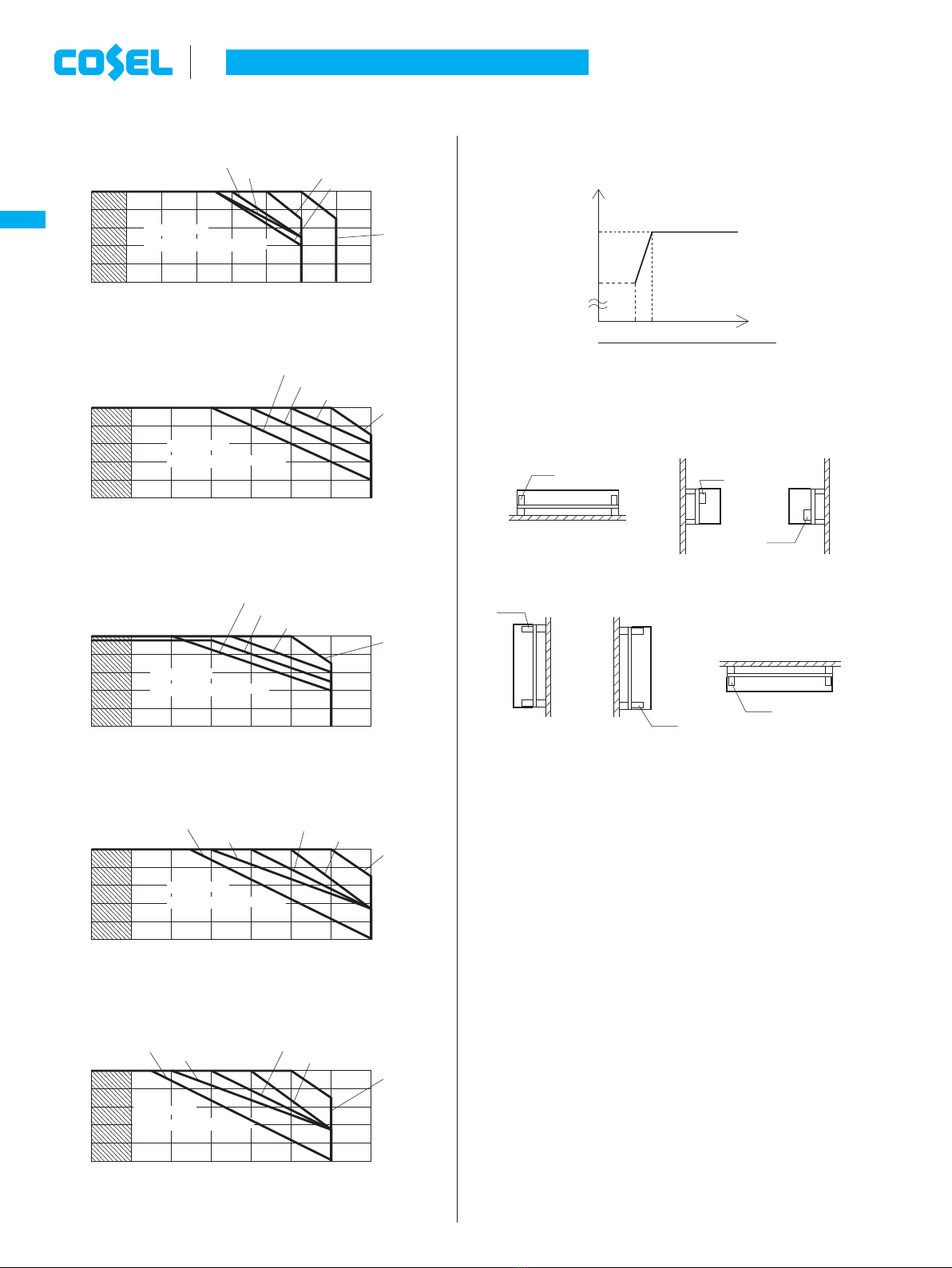
1.4 Overvoltage protection
¡An overvoltage protection circuit is built-in. The AC input should
be shut down if overvoltage protection is in operation. The mini-
mum interval of AC recycling for recovery is 1.5 minutes (LGA240A
is 3minutes).
*The recovery time varies depending on input voltage.
¡Series operation is available by connecting the outputs of two or
more power supplies with the same output voltage, as shown be-
low. Output current in series connection should be lower than the
lowest rated current in each unit.
¡Parallel operation is not possible.
¡Redundancy operation is available by wiring as shown below.
¡Even a slight difference in output voltage can affect the balance
between the values of I1and I2.
Please make sure that the value of I3does not exceed the rated
current of a power supply.
I3[the rated current value
1 Function Remarks:
Please avoid applying the over-rated voltage to the output termi-
nal. Power supply may operate incorrectly or fail.In case of oper-
ating a motor etc. , please install an external diode on the output
terminal to protect the unit.
1.5 Output voltage adjustment range
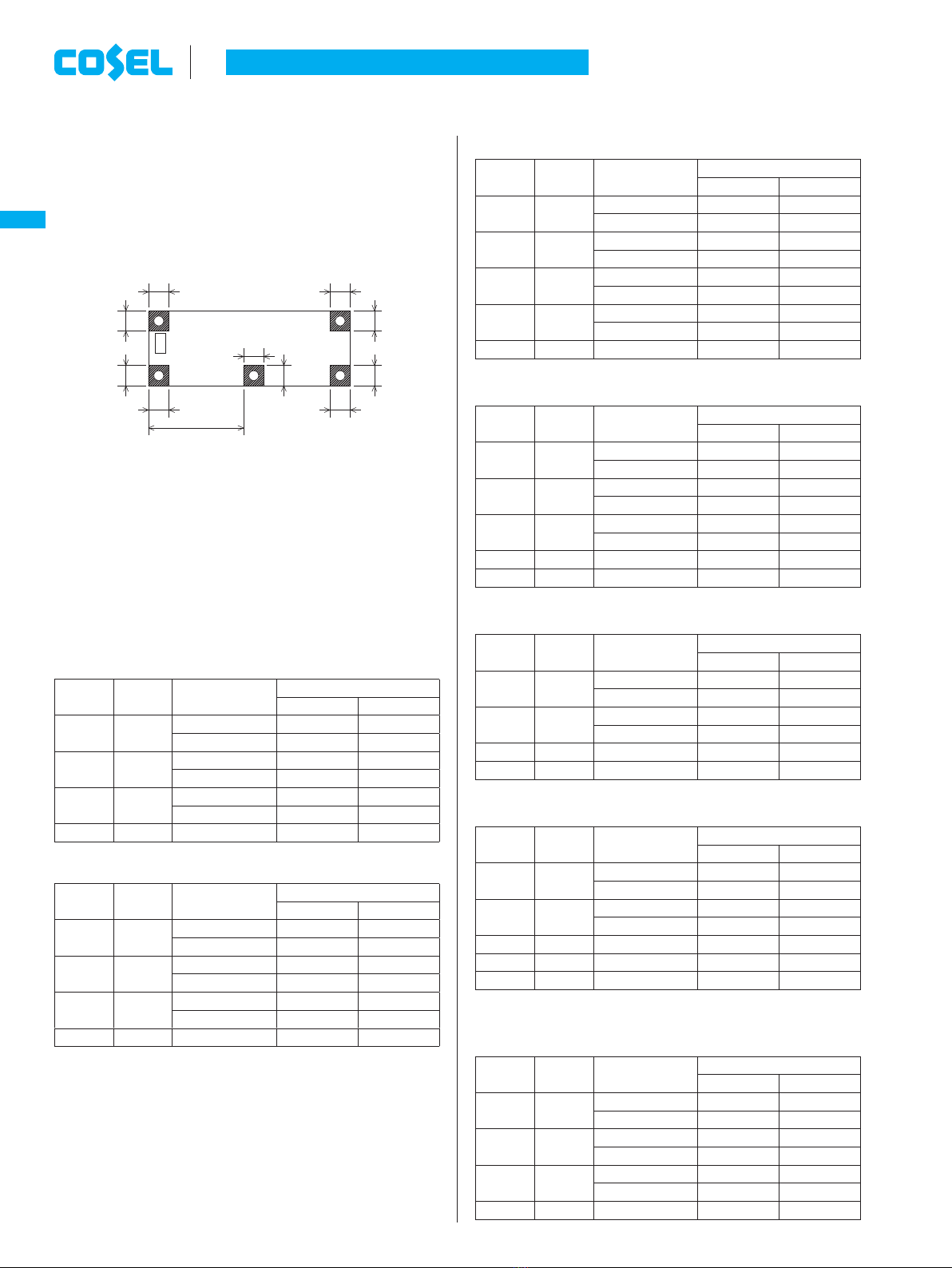
¡Adjustment of output voltage is possible by using potentiometer.
Please refer to instruction manual 5.1.
¡Option ”-Y” is recommended which can adjust the output voltatge.
1.6 Isolation
¡For a receiving inspection, such as Hi-Pot test, gradually increase
(decrease) the voltage for the start (shut down). Avoid using Hi-
Pot tester with the timer because it may generate voltage a few
times higher than the applied voltage, at ON/OFF of a timer.
2 Series Operation and
Parallel Operation
AC-DC Power Supplies Open Frame/ Enclosed Type
Instruction Manual
LGA-14
LGA
I2
I1I3
-
+
+
-
Load
Power
Supply
Power
Supply
Load
(a) (b)
Load Load
Power
Supply
+
-
Power
Supply
+
-
Power
Supply
+
-
+
-
Power
Supply
Fig.2.1 Examples of connecting in series operation
Fig.2.2 Example of redundancy operation
melga1.inddLGA-14me lga1 indd LGA-14 2015/06/1914:42:252015/06/19 14:42:25