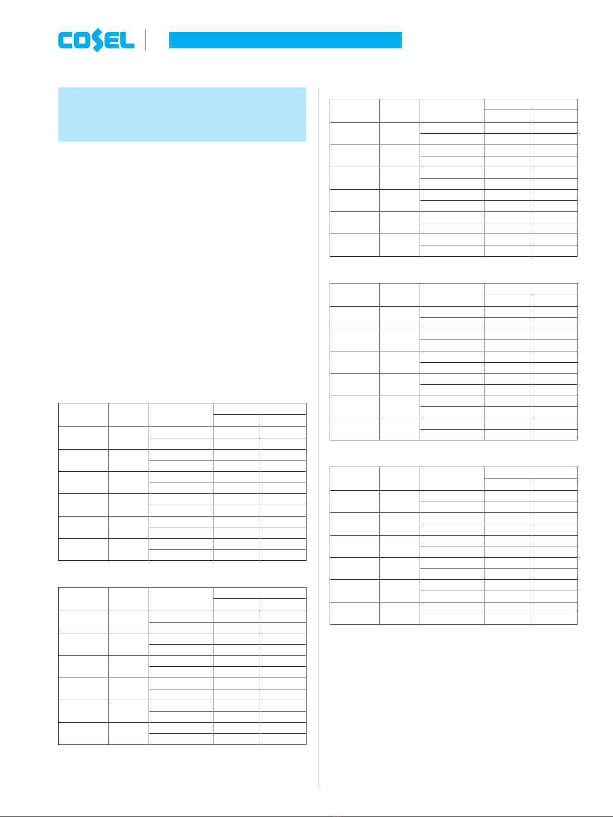
Table 3.6 Temperatures of Point A, Point B
LGA240A-O
Mounting
Method
Cooling
Method Load factor Max temperature
Point A[C] Point B[C]
A
Convection
35%<Io[100% 77 77
Io[35% 75 76
B
Convection
35%<Io[100% 71 74
Io[35% 71 74
C
Convection
35%<Io[100% 77 72
Io[35% 77 72
D
Convection
35%<Io[100% 82 71
Io[35% 82 71
E
Convection
35%<Io[100% 61 79
Io[35% 65 74
A,B,C,D,E,F Forced air 70%<Io[100% 80 75
Io[70% 75 70
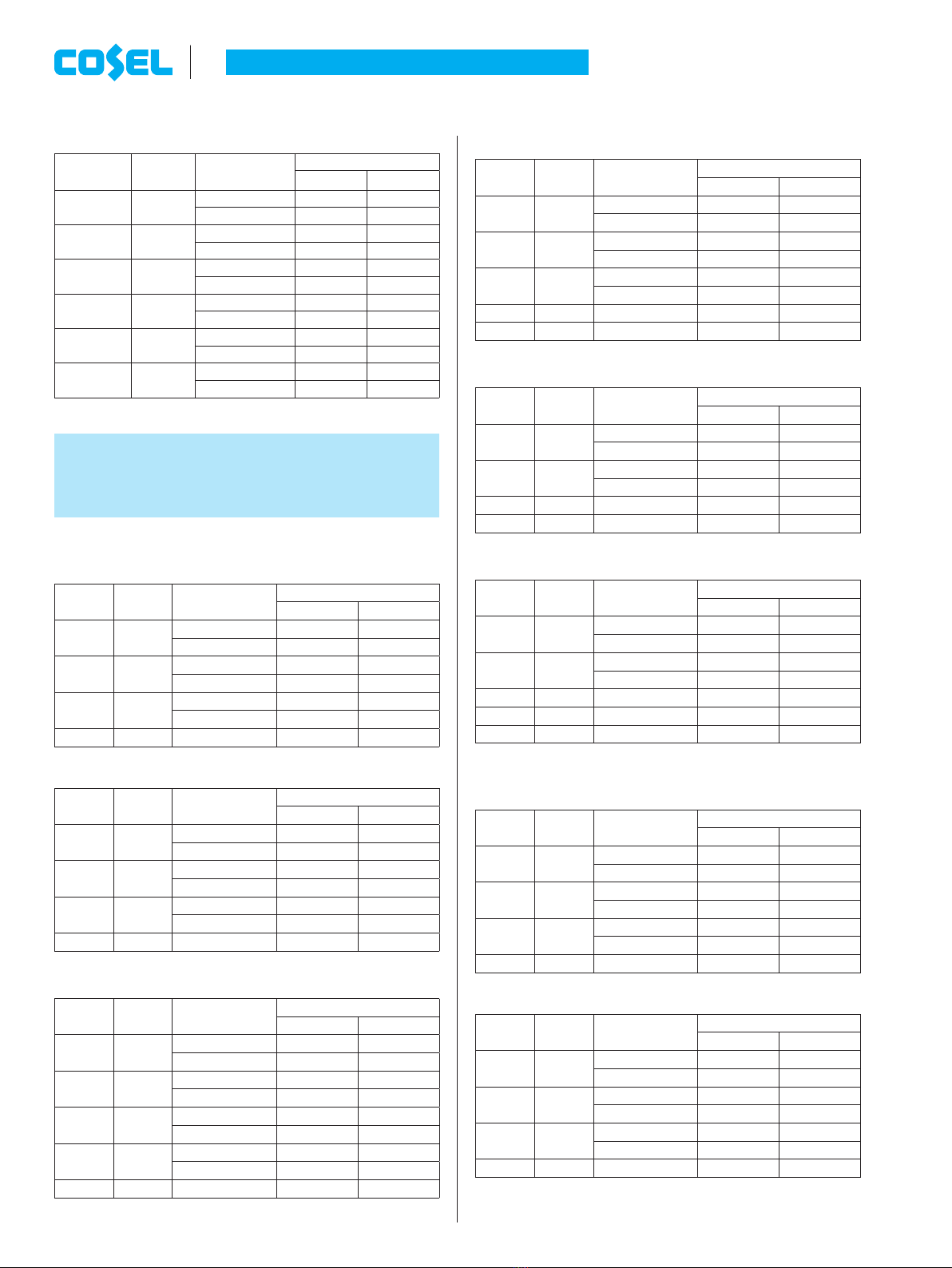
4 Life expectancy and
warranty
¡Life Expectancy.
Table 4.1 Life Expectancy (LGA50A-3R3-Y, -5, -12, -15)
Mounting
Method
Cooling
Method
Average ambient
temperature (year)
Load factor
Io[75%
75%<Io[100%
A Convection Ta = 40Cor less 10years or more 8years
Ta = 50C8years 4years
B , C , D Convection Ta = 30Cor less 10years or more 9years
Ta = 40C10years or more 4years
E
Convection Ta = 20Cor less 10years or more 10years or more
Ta = 30C10years or more 9years
A,B,C,D,E,F
Forced air Ta = 60C5years 3years
Table 4.2 Life Expectancy (LGA50A-24, -48)
Mounting
Method
Cooling
Method
Average ambient
temperature (year)
Load factor
Io[75%
75%<Io[100%
A Convection Ta = 35Cor less 10years or more 10years or more
Ta = 45C10years or more 5years
B , C , D Convection Ta = 30Cor less 10years or more 10years or more
Ta = 40C10years or more 6years
E Convection Ta = 20Cor less 10years or more 10years or more
Ta = 30C10years or more 10years or more
A,B,C,D,E,F
Forced air Ta = 50C5years 3years
Table 4.3 Life Expectancy
(
LGA75A-O
)
Mounting
Method
Cooling
Method
Average ambient
temperature (year)
Load factor
Io[75%
75%<Io[100%
A Convection Ta = 40Cor less 10years or more 8years
Ta = 50C9years 4years
B , C Convection Ta = 30Cor less 10years or more 10years or more
Ta = 40C10years or more 6years
D Convection Ta = 25Cor less 10years or more 10years or more
Ta = 35C10years or more 7years
E Convection Ta = 20Cor less 10years or more 10years or more
Ta = 30C10years or more 7years
A,B,C,D,E,F
Forced air Ta = 60C5years 3years
Table 4.4 Life Expectancy
(
LGA100A-O
)
Mounting
Method
Cooling
Method
Average ambient
temperature (year)
Load factor
Io[75%
75%<Io[100%
A Convection Ta = 40Cor less 10years or more 6years
Ta = 50C8years 3years
B Convection Ta = 30Cor less 10years or more 10years or more
Ta = 40C10years or more 9years
C , E Convection Ta = 25Cor less 10years or more 6years
Ta = 35C9years 3years
D Convection Ta = 30Cor less 10years or more 8years
A,B,C,D,E,F
Forced air Ta = 60C5years 3years
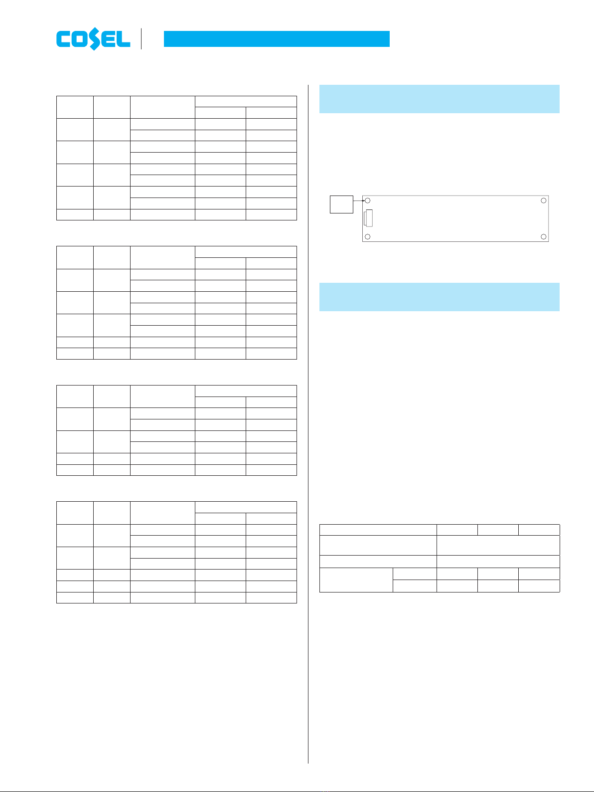
Table 4.5 Life Expectancy
(
LGA150A-O
)
Mounting
Method
Cooling
Method
Average ambient
temperature (year)
Load factor
Io[75%
75%<Io[100%
A Convection Ta = 30Cor less 10years or more 10years or more
Ta = 40C10years or more 4years
B , C Convection Ta = 20Cor less 10years or more 9years
Ta = 30C10years or more 4years
D , E Convection Ta = 20Cor less 10years or more 6years
A,B,C,D,E,F
Forced air Ta = 50C5years 3years
Table 4.6 Life Expectancy
(
LGA240A-O
)
Mounting
Method
Cooling
Method
Average ambient
temperature (year)
Load factor
Io[75%
75%<Io[100%
A Convection Ta = 30Cor less 10years or more 10years or more
Ta = 40C10years or more 8years
B , C Convection Ta = 20Cor less 10years or more 10years or more
Ta = 30C10years or more 10years or more
D Convection Ta = 20Cor less 10years or more 10years or more
E Convection Ta = 15Cor less 10years or more 5years
A,B,C,D,E,F
Forced air Ta = 50C5years 3years
¡Warranty
Table 4.7 Warranty
(
LGA50A-3R3-Y, -5, -12, -15
)
Mounting
Method
Cooling
Method
Average ambient
temperature (year)
Load factor
Io[75%
75%<Io[100%
A Convection Ta = 40Cor less 5years 5years
Ta = 50C5years 3years
B , C , D Convection Ta = 30Cor less 5years 5years
Ta = 40C5years 3years
E Convection Ta = 20Cor less 5years 5years
Ta = 30C5years 3years
A,B,C,D,E,F
Forced air Ta = 60C5years 3years
Table 4.8 Warranty
(
LGA50A-24, -48)
Mounting
Method
Cooling
Method
Average ambient
temperature (year)
Load factor
Io[75%
75%<Io[100%
A Convection Ta = 35Cor less 5years 5years
Ta = 45C5years 3years
B , C , D Convection Ta = 30Cor less 5years 5years
Ta = 40C5years 3years
E Convection Ta = 20Cor less 5years 5years
Ta = 30C5years 3years
A,B,C,D,E,F
Forced air Ta = 50C5years 3years
AC-DC Power Supplies Open Frame/ Enclosed Type
Instruction Manual
LGA-18 June 26, 2020