Cosel AME600F User manual

Basic Characteristics Data
Model Circuit method
Switching
frequency
[kHz]
Inrush
current
protection
circuit
PCB/Pattern
Series/Parallel
operation availability
Material
Single
sided Double
sided Series
operation Parallel
operation
Input module of
AME600F
Active filter 67 Relay FR-4 - Ye s N/A N/A
Half-bridge converter 133
Input module of
AME1200F
Active filter 67 Relay FR-4 - Ye s N/A N/A
Half-bridge converter 133
Output module of
A-D Buck converter 266 - FR-4 - Ye s ○*1N/A
*1Series operation is possible with the same output modules.
AME-6

1 Terminal Blocks AME-8
3
Series / Parallel operation in Modular power supply
AME-11
3.1 Series operation AME-11
4Functions AME-11
5Assembling and Installation Method AME-14
4.1 Input voltage range AME-11
4.2 Inrush current limiting AME-11
4.3 Overcurrent protection AME-11
4.4 Thermal protection AME-11
4.5 Overvoltage protection AME-12
4.6 Output ripple and ripple noise AME-12
4.7 Output voltage adjustment AME-12
4.8 Remote ON/OFF (RC) AME-12
4.9 Global inhibit (GI) AME-12
4.10 Isolation AME-13
4.11 Alarm AME-13
4.12 Auxiliary power (AUX) AME-14
4.13 Medical Isolation grade AME-14
5.1 Installation method AME-14
5.2 Output side attaching externally capacitor AME-14
5.3 Derating AME-15
5.4 Life expectancy and Warranty AME-15
2
Conguration - Model Name Construction
AME-10
AC-DC Power Supplies Congurable Type
Instruction Manual
AME-7

1 Terminal Blocks
¿ AME600F
⑥
⑤
④
③
②
①
SLOT
4 3 2 1
¿ AME1200F
②
①
③
④
⑤
⑥
3456 2 1
SLOT
1AC (L) Input Terminals 85 - 264VAC 1f45 - 66Hz
2AC (N) (M4)
3Frame ground (M4)
4CN1
5CN2 connectors
6LED (PR ALARM)
Connector pin numbers
2
8 7
1
10 9
2 1
CN2
CN1
Table 1.1 Pin conguration and function of CN1
Pin No. Function Ground
level
1 AUX : Auxiliary power
AUXG
2 AUXG : Auxiliary power ground
3 GI1 : Global inhibit
4 AUXG : Auxiliary power ground
5 GI2 : Global inhibit GIG
6 GIG : Global inhibit ground
7 N.C. : No connection -
8 N.C. : No connection
9 PR : PR Alarm PRG
10 PRG : PR Alarm ground
Table 1.2 Pin conguration and function of CN2
Pin No. Function Ground
level
1 N.C. : No connection
-
2 N.C. : No connection
3 N.C. : No connection
4 N.C. : No connection
5 N.C. : No connection
6 N.C. : No connection
7 N.C. : No connection
8 N.C. : No connection
*Do not connect anything to N.C. pins.
Table 1.3 Matching connectors and terminals
Connector Housing Terminal Mfr.
CN1
S10B-PHDSS PHDR-10VS
Reel : SPHD-002T-P0.5
Loose : BPHD-001T-P0.5 *1
BPHD-002T-P0.5 *1
J.S.T
*1 The manufacturer prepares only the ratchet hand.
AC-DC Power Supplies Congurable Type
Instruction Manual
AME-8

¿ Output module
12
10 9
Module : A-D
⑤
④
③
②
①
1-Output
2+Output
3CN3 (connector)
4LED (DC_OK)
5Potentiometer to adjust output voltage
Table 1.4 Pin conguration and function of CN3 (Applying module:A-D)
Pin No. Function Ground
level
1 RC : Remote ON/OFF RCG
2 RCG : Remote ON/OFF ground
3LV : LV Alarm LVG
4LVG : LV Alarm ground
5 N.C. : No connection
-
6 N.C. : No connection
7 N.C. : No connection
8 N.C. : No connection
9 N.C. : No connection
10 N.C. : No connection
*Do not connect anything to N.C. pins.
Table 1.5 Matching connectors and terminals
Connector Housing Terminal Mfr.
CN3
S10B-PHDSS PHDR-10VS
Reel : SPHD-002T-P0.5
Loose : BPHD-001T-P0.5 *1
BPHD-002T-P0.5 *1
J.S.T
*1 The manufacturer prepares only the ratchet hand.
AC-DC Power Supplies Congurable Type
Instruction Manual
AME-9

2
Conguration - Model
Name Construction
The AME series has Order Name which is used for the ordering
aside from Model Name. Please contact us for the detail.
¡Model Name Construction
AM
654321
Code Code
123456
Bar for Series
Bar for Parallel
Output modules
slot
1 2 3 4 5
1 Model
AM=AME series
2 Power
06=600W, 12=1200W
3 Output module conguration
The output module codes are showed in the specications.
When the slot is blank, “O” (Alphabet) needs to be set.
¶The number of slot is different depending on the model.
4 Parallel code
Refer to Table2.1 Parallel and Series Code.
5 Series code
Refer to Table2.1 Parallel and Series Code.
<Model Name Example>
AM12 ODCCBA C
0004
Example of option
Parallel connection is not necessary.
Slot1 Module A 5V 12A
Slot2 Module B 12V 8.5A
Slot3, 4
Two Module C in series
at 48V 5A
Slot5 Module D 48V 2.5A
Slot6 is blank
AME1200F
¡Order Name Construction
1to 3are same rules as Model Name, after that add manage-
ment number (6 digits).
Parallel and series code are not listed on Order name.
<Order Name example>
AM12 - O D C C B A - OOOOOOO: Alphanumeral
O: management number (6digits)
¿Note
(1) Please select the output module codes from the specications
to correspond with required voltage and current.
Please select ”O” when the slot is blank.
(2) If the output modules need to be connected in parallel or se-
ries, please select Parallel or Series code from Table2.1.
(3) At least two slots have to be occupied.
(4) The following is the list of modules which can be used in series
or parallel operation.
Available output modules
Series setting A - D
Parallel setting -
Table2.1 Parallel and Series Code.
Slot4Slot5Slot6 Slot3 Slot2 Slot1
00
01
02
03
04
05
06
07
08
09
0A
0B
0C
0D
0E
0F
10
11
12
13
14
15
16
17
18
19
1A
1B
1C
1D
1E
1F
Code
: Output terminal
: Connection
AME600F AME1200F
AC-DC Power Supplies Congurable Type
Instruction Manual
AME-10

3
Series / Parallel operation
in Modular power supply
3.1 Series operation
¡Series operation is possible only between identical output mod-
ules.
The copper bar for series connection is assembled before ship-
ping.
¡The output current in series operation is the same as the one of
the individual modules that are connected.
¡Please note the following items,
1Only same modules can be connected in series.
2Total of the rated voltage in series has to be 48V or less.
Adjusting output voltage is possible within 60V.
3The series operation is not available along with the parallel op-
eration.
Please contact us for any other conditions.
¡When in series, the output voltage at the start-up might have the
step as shown in Fig.3.1.
AC Input voltage
Input ON
Output voltage
Fig.3.1 Start-up waveform in series operation
4 Functions
4.1 Input voltage range
¡The input voltage range is from 85 VAC to 264 VAC.
The rated input voltage range for the safety approvals is from
100VAC to 240VAC (50/60Hz).
¡If the input voltage was out of the above range, the power supply
might not meet the specication or might fail.
Please do not apply the square wave of the UPS, the inverter and
so on to the power supply.
4.2 Inrush current limiting
¡If the switch is installed on the input, please select the one which
can work at the inrush current.
¡The relay is used in the inrush current limiting circuit. If the interval
of the input on/off was short, the inrush current limiting might not
work correctly. So, please make its interval long enough.
And, it makes the primary and the secondary inrush current.
4.3 Overcurrent protection
¡The overcurrent protection which will activate at 105% or more of
the rated current is built in. The output will automatically recover
when the overcurrent condition is resolved.
Please do not use the unit with short circuit and/or under the over-
current condition.
¡Hiccup mode
When the overcurrent protection circuit activates and the output
voltage drops, the output will get intermittent so that the average
current decreases.
4.4 Thermal protection
¡The unit has the thermal protection.
¡The thermal protection circuit might activate and shut down the
output under the following conditions.
1The case that the output current and/or the ambient tempera-
ture exceed the derating curve.
2The case that the fan stops working or the air volume is de-
creased by blocking the fan.
When the thermal protection activates, outputs on all output mod-
ules will shut down.
When either one of the following actions is taken, the output will
recover.
1Turn the input voltage off and solve all of overheating cause.
Then, turn the input on after enough time to cool the unit down.
2Turn all outputs off by GI terminal and solve all of overheating
cause. Then, turn all outputs on by GI terminal after enough
time to cool the unit down.
AC-DC Power Supplies Congurable Type
Instruction Manual
AME-11

4.5 Overvoltage protection
¡When the overvoltage protection activates, outputs on all output
modules will shut down.
When either one of the following actions is taken, the output will
recover.
1Turn the input voltage off and solve all of overvoltage cause.
Then, turn the input on after ten seconds.
2Turn all outputs off by GI terminal and solve all of overvoltage
cause.
Then, turn all outputs on by GI terminal after ten seconds.
* The recovery time varies depending on such factors as input
voltage.
¡If the external voltage was applied to the output of the power sup-
ply, the internal components might be damaged.
4.6 Output ripple and ripple noise
¡The measurement environment would affect the output noise.
Fig.4.1 is the recommended measurement method.
+Vout
-Vout
Load
150mm
C
1
Osiloscope/
Ripple noise meter
Bw:20MHz
Differential probe
+
C1 : Aluminum electrolytic capacitor 22μF
Fig.4.1 Measuring method of Ripple and Ripple Noise
Remarks :
The output ripple and noise might not be measured correctly by
the ux of magnetic force from the power supply which crosses
the ground wire of the probe.
Bad example Good example
Fig.4.2 Example of measuring output ripple and noise
4.7 Output voltage adjustment
¡To increase the output voltage, turn the built-in potentiometer
clockwise.
To decrease the output voltage, turn it counterclockwise.
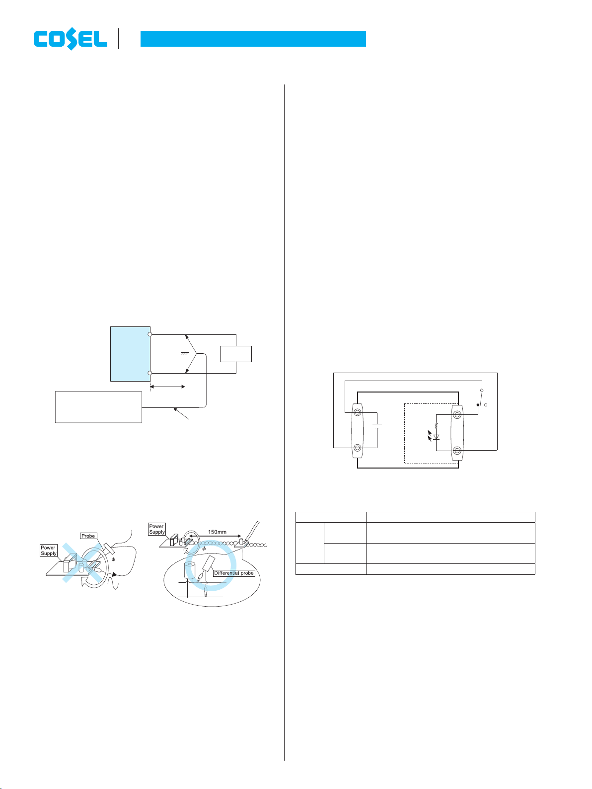
4.8 Remote ON/OFF(RC)
¡Each output module have remote ON/OFF functions. The output
voltage can be turned on/off by the signal to RC terminal in CN3
on each modules.
¡The remote ON/OFF circuit (RC, RCG) is isolated from the input,
the output, FG and other function terminals.
¡Auxiliary power (AUX) for remote ON/OFF.
The power supply has the auxiliary power (AUX) for the remote
ON/OFF.
The auxiliary power (AUX) is isolated from input, output, and FG.
Fig. 4.3 is the example of the remote ON/OFF with AUX.
¡Please note the followings for the remote ON/OFF function.
1 The output stops when 4.5V to 12.5V of the voltage is applied
to RC.
2 The built-in fan does not stop even if the output is turned OFF
by the remote ON/OFF.
3 When the output is turned off by the remote on/off, the LV alarm
will be delivered.
4This function individually operates on each output module.
¡The Remote ON/OFF circuit on each output module can operate
individually.
The detail of the “Global inhibit function” to turn all output modules
off at the same time is shown in the item 4.9.
CN3
CN1
RC
AUX
AUXG
RCG
SW
Output module
Output
on
Output
off
Ri=
1.8KΩ
Fig.4.3 Example of remote ON/OFF
Table 4.1 Remote ON/OFF specication
Connection method
Fig4.3 Remote SW
SW
Logic
Output on SW open
(0-0.5V between RC and RCG)
Output off SW short
(4.5-12V between RC and RCG)
Bases pin CN3 RCG
4.9 Global inhibit (GI)
¡The unit has the Global inhibit function.
Global inhibit is the control signal input which turns all outputs off
by supplying the current into GI2.
Table 4.2 is specications and Fig.4.4 is use examples for Global
inhibit.
¡The Global inhibit circuit (GI2, GIG) is isolated from input, output,
FG, AUX and other function terminals.
¡Please note the followings when using the Global inhibit function.
1The output can be turned off by supplying the current into GI2
pin.
2The current into GI2 pin is 3mA typ (12mA max).
3 The PR signal will get “High” when all output modules are
turned off by the Global inhibit function.
AC-DC Power Supplies Congurable Type
Instruction Manual
AME-12

4 The built-in fans will stop when all output modules are turned off
by the Global inhibit function.
5AUX is available even when outputs are turned off by Global
inhibit.
6If the voltage or the current which exceeds the value in table 4.2
were supplied into GI2 pin, the output might not be generated
correctly.
7Start time is 1,000ms max.
Table 4.2 Global inhibit specication
Connection method
Fig4.4 (a) Fig4.4 (b) Fig4.4 (c)
SW
Logic
Output on SW open
(0.1mA max)
SW open
(0.1mA max)
SW short
(0.5V max)
Output off SW short
(1.5mA min)
SW short
(1.5mA min)
SW open
(0.1mA max)
Bases pin GIG AUXG GIG,AUXG
AUX
150Ω
5V
typ
GI2
GIG
AUXG
2.2kΩGI1
GI1
GI2
R1
V1
2.2kΩ
CN1 CN1
CN1
AUXG
GIG
150Ω
5V
typ
AUX
150Ω
5V
typ
GI2
GIG
AUXG
2.2kΩGI1
Example R1:1kΩ V1:5V
(a)
(b)
(c)
SW
SW
SW
Fig.4.4 Examples of connection Global inhibit circuit
4.10 Isolation
¡When the Hi-Pot test for the receiving inspection, etc is conduct-
ed, the voltage should be increased gradually. Also, the voltage
should be decreased gradually by using the dial. Please do not
use the Hi-pot tester which has the timer because it might gener-
ate unwanted high voltage when timer is on.
¡When the isolation test between the input and the output, the input
and the FG and the output and the FG is conducted, all outputs
and terminals for all functions should be shorted.
4.11 Alarm
¡The unit has two typs of alarm below. Table 4.3 is the detail of the
alarm.
1PR: abnormal input voltage, fan alarm
2LV: drop and shut-off of output voltage
Table 4.3 Explanation of alarms
Alarm Output of alarm
PR
When the input voltage is
abnormal (low input voltage) or
the fan stops, the alarm signal is
generated from CN1.
Open collector method
Good:Low (0.5Vmax at
5mA)
Fail:High (50Vmax)
LV
When the rated output voltage
decreases or stops, the alarm
signal is generated from CN3.
Note:
When the overcurrent protection
activates, the alarm will be
unstable.
Open collector method
Good:Low (0.5Vmax at
5mA)
Fail:High (50Vmax)
Please contact us for details.
100kW0.1mF
PR
PRG
Fig.4.5 PR internal circuit
100kW0.1mF
LV
LVG
Fig.4.6 LV internal circuit
¡Please note the followings when you use the alarm (LV signal).
1If the output voltage is turned off by the remote ON/OFF circuit,
the LV signal will get “High”.
2 The LV signal may get “High”, if the output voltage drops to 40%
or less of the rated voltage.
¡The LV signal (Alarm) circuit is isolated from input, output, FG and
other function terminals.
AC-DC Power Supplies Congurable Type
Instruction Manual
AME-13

4.12 Auxiliary power (AUX)
¡The unit has the auxiliary power (AUX: 5V1A) in CN1 to provide
for the remote ON/OFF and external circuits.
¡When the Global inhibit function activates, the following derating
for the AUX is required.
Derating for AUX: Io(AUX) [0.5A
¡The AUX circuit(AUX, AUXG) is isolated from the input, the output,
the FG, and other function terminals except GI1.
¡If the output current of the AUX exceed 1A, the unit might be dam-
aged or malfunction.
When the DC-DC converter is connected to the AUX, the cur-
rent might be severalfold of the normal current when starting up.
Please check the current.
¡The maximum external capacitor to the AUX is 47μF.
4.13 Medical Isolation grade
¡AME series meets 2MOPP
1MOPP
Safety GND
primarysecondary
2MOPP
Fig.4.7 Medical Isolation Grade
5 Assembling and
Installation Method
5.1 Installation method
¡The unit has cooling fans.
Ensure that the inlet and outlet vents are not blocked.
Output
module
Air flow
FAN
Fig.5.1 Air ow
¡Fig.5.2 is the recommended installation method when the unit is
mounted by screws. When the unit is installed by any other meth-
od, please take into account of its weight and secure it.
A
B
C
Top Top Top
CN1
CN1
CN1
Fig.5.2 Installation method 1
¡Avoid installation method 2 as shown in Fig.5.3, which can cause
stress on the mounting holes.
¡Maximum length of mounting screws is 6mm (Refer to Fig.5.4).
NO
CN1
TOP
Chassis of
customer system
Screw M4
Chassis of
AME series
6mm max
Fig.5.3 Installation method 2 Fig.5.4 Mounting screw
5.2 Output side attaching externally capacitor
¡If the external capacitor is too large, the power supply might not
start up.
Table 5.1 Connectable External capacitor on the output side [μF]
module code capacitance
A 0 to 47,000
B 0 to 18,000
C 0 to 12,000
D 0 to 2,200
AC-DC Power Supplies Congurable Type
Instruction Manual
AME-14

5.3 Derating
¡The AME series is comprised multiple combination output. Both
the maximum output of each module and total maximum output
have to be within the specs.
¡Derating curve for ambient temperature
The derating curve for the ambient temperature (inlet temperature
for cooling) of output modules is shown in Fig.5.5.
The specications of the ripple and noise in the shaded area be-
low are different.
0
20
40
60
50
80
100
-20 -10 0 10 20 30 40 50 60 70
Ambient temperature [
℃
]
Load of output module [%]
Vin=85 to 264VAC
※
(a) AME600F
0
20
40
60
50
80
100
-
20
-
10 0 10 20 30 40 50 60 70
Ambient temperature [
℃
]
Load of output module [%]
①
Vin=85 to 170VAC
※
②
Vin=170 to 264VAC
①
②
(b) AME1200F
Fig.5.5 Derating curve for ambient temperature
*With derating due to input voltage
¡Derating curve for input voltage
The derating curve with respect to input voltage is shown in
Fig.5.6 and Fig.5.7.
200
320
400
500
700
Input voltage [VAC]
Total output power [W]
600
85 90 150 170 264
300
Fig.5.6 Derating curve for input voltage (AME600F)
700
800
1000
1100
1300
Input voltage [VAC]
Total output power [W]
1200
85 90 150 170 264
900
Fig.5.7 Derating curve for input voltage (AME1200F)
¡Dention of load factor
Load [%] = maximum value in A0to A6
A0 =×100
(Sum of each module power)
(Total output power)
= ×100
(Total output power)
(Ik ×Vk)
6
k=1
A1, A2, A3, A4, A5, A6: calculated by Ak= Ik/ I0× 100
Total output power : Dependent on input voltage (Refer to g.5.6
and Fig.5.7)
Ik, Vk, I0k : output current, voltage, and rated current
The sufx k means the k-th slot.
5.4 Life expectancy and Warranty
¡Life expectancy
Life expectancy is as follows.
Table.5.2 Life expectancy (AME600F)
Mounting
method
Input
Voltage
Average ambient
temperature (yearly)
Life expectancy
0% [Io [75% 75% < Io [100%
All
mounting
direction
85 to
170VAC
Ta = 40Cor less
10 years 4 years
Ta = 50C
7 years 2 years
170 to
264VAC
Ta = 40Cor less
10 years 4 years
Ta = 50C
7 years 2 years
Table.5.3 Life expectancy (AME1200F)
Mounting
method
Input
Voltage
Average ambient
temperature (yearly)
Life expectancy
0% [Io [75% 75% < Io [100%
All
mounting
direction
85 to
170VAC
Ta = 30Cor less
10 years 9 years
Ta = 40C
10 years 4 years
170 to
264VAC
Ta = 40Cor less
10 years 4 years
Ta = 50C
7 years 2 years
AC-DC Power Supplies Congurable Type
Instruction Manual
AME-15

¡Life expectancy (R(t)=90%) of fan depends on use conditions as
shown in Fig.5.8.
Life expectancy of fan [H]
Ambient temperature[C]
4030 50 60 70 8
0
500,000
100,000
10,000
Fig.5.8 Life expectancy of fan
¡Warranty term
Warranty is as follows and shall be 5 years maximum.
Warranty does not apply if used outside of derating specications.
Table.5.4 Warranty term (AME600F)
Mounting
method
Input
Voltage
Average ambient
temperature (yearly)
Warranty term
0% [Io [75% 75% < Io [100%
All
mounting
direction
85 to
170VAC
Ta = 40Cor less
5 years 4 years
Ta = 50C
5 years 2 years
170 to
264VAC
Ta = 40Cor less
5 years 4 years
Ta = 50C
5 years 2 years
Table.5.5 Warranty term (AME1200F)
Mounting
method
Input
Voltage
Average ambient
temperature (yearly)
Warranty term
0% [Io [75% 75% < Io [100%
All
mounting
direction
85 to
170VAC
Ta = 30Cor less
5 years 5 years
Ta = 40C
5 years 4 years
170 to
264VAC
Ta = 40Cor less
5 years 4 years
Ta = 50C
5 years 2 years
AC-DC Power Supplies Congurable Type
Instruction Manual
AME-16
This manual suits for next models
1
Table of contents
Other Cosel Power Supply manuals

Cosel
Cosel UAW125S User manual

Cosel
Cosel LHA30F User manual

Cosel
Cosel UAF500S Series User manual

Cosel
Cosel PCA600F User manual

Cosel
Cosel LCA10S User manual

Cosel
Cosel LGA50A User manual

Cosel
Cosel RBC200F User manual

Cosel
Cosel AD240 User manual

Cosel
Cosel MMB50A User manual

Cosel
Cosel AME Series User manual

Cosel
Cosel PAA50F User manual

Cosel
Cosel FETA2500B User manual

Cosel
Cosel GHA300F User manual

Cosel
Cosel PLA100F User manual

Cosel
Cosel KL Series User manual

Cosel
Cosel LDA10F User manual

Cosel
Cosel PCA Series User manual

Cosel
Cosel HCA3500TF-48 User manual

Cosel
Cosel SNA-01 User manual

Cosel
Cosel LMA Series User manual