manuals.online logo
Brands
  1. Home
  2. •
  3. Brands
  4. •
  5. Crestron
  6. •
  7. Transmitter
  8. •
  9. Crestron DigitalMedia 8G 401 Series Dimensional drawing

Crestron DigitalMedia 8G 401 Series Dimensional drawing

DO GUIDE
PC Connector Pin Assignments
DM-TX-401-S/DM-TX-401-S2
DigitalMedia 8G™ Fiber Transmitter 401
DO Install the Device
The DM-TX-401-S and DM-TX-401-S2 can be placed on a at surface, mounted into a rack, or
attached to the underside of a table. If rack mounting is desired, use the ST-RMK Rack Mount
Kit (sold separately). If under-table mounting is desired, use the UTK-1U-HALF Under-Table
Mounting Kit (sold separately).
DO Connect the Device
Connect the device as appropriate for the installation (refer to illustrations through ).
DM-TX-401-S and DM-TX-401-S2 Front Panel Connections (DM-TX-401-S Shown)
DM-TX-401-S Rear Panel Connections
DO Check the Box
QTY PRODUCT PART NUM.
1Connector, 2-Pin 20 03574
1Connector, 5-Pin 2003577
1 Power Pack, 24 Vdc 0.75 A, 100-240 Vac 2045865
Not Included: Cables, Mounting Kits
Mouse/Keyboard Input
USB HID RESET
DM
LINK SETUP AUTO VIDEO HDMI
DISPLAY
PORT SELECT
DM-TX-401-S
PWR PC
INPUT
10BASE-T/
100BASE-TX
Ethernet to Local
Network Device†
24V 0.75A
from Power Pack
(Included)
To DM
®
Switcher,
Receiver, or Other
DM Device
Unbalanced Stereo
Line Level
Audio Input
To Any
RS-232
Device
To IR Device
(e.g., Projector)
or Devices
without RS-232
Ground
DisplayPort
Digital Video/
Audio Input
HDMI®
Digital Video/
Audio Input
RGB,
Component,
S-Video, or
Composite
Video Input*
Composite
Video
Input
Unbalanced Stereo
Line Level Audio Input
*Refer to illustration for PC connector pin assignments.
† Refer to illustration for LAN connector pin assignments.
MMF/SC
VID PC
VIDEO IN
AUDIO IN
HDMI DISPLAY PORT
LR
G
TX
RX
RS
CS
L
I
N
K
C
O
M
CLASS 1
LASER
PRODUCT
DM OUT
IR
S G
24V 0.75A LAN
G
10BASE-T/
100BASE-TX
Ethernet to Local
Network Device
†
24V 0.75A
from Power Pack
(Included)
To DM Switcher,
Receiver, or Other
DM Device
Unbalanced Stereo
Line Level
Audio Input
To Any
RS-232
Device
To IR Device
(e.g., Projector)
or Devices
without RS-232
Ground
DisplayPort
Digital Video/
Audio Input
HDMI
Digital Video/
Audio Input
RGB,
Component,
S-Video, or
Composite
Video Input*
Composite
Video
Input
Unbalanced Stereo
Line Level Audio Input
*Refer to illustration for PC connector pin assignments.
† Refer to illustration for LAN connector pin assignments.
VID PC
VIDEO IN
HDMI DISPLAY PORT
AUDIO IN
LR
G
TX
RX
RS
CS
L
I
N
K
C
O
M
DM OUT
CLASS 1
LASER
PRODUCT
S G
IR G
LAN
SMF/LC 24V 0.75A
DM-TX-401-S2 Rear Panel Connections
PIN NUM. RGB YPbPr S-VIDEO COMPOSITE
1 R Pr C
2 G Y Y
3 B Pb COMP
5GND GND GND GND
6RED_GND Pr_GND C_GND
7GRN_GND Y_GND Y_GND
8BLU_GND Pb_GND
13 H
14 V
NOTE: For best video performance, ground connections
should be kept separate. Do not connect ground wires to the
connector shell. The connector shell is reserved for the cable
shield.
Pin 10
Pin 5 Pin 1
Pin 6
Pin 15 Pin 11
51
11
15
DO GUIDE
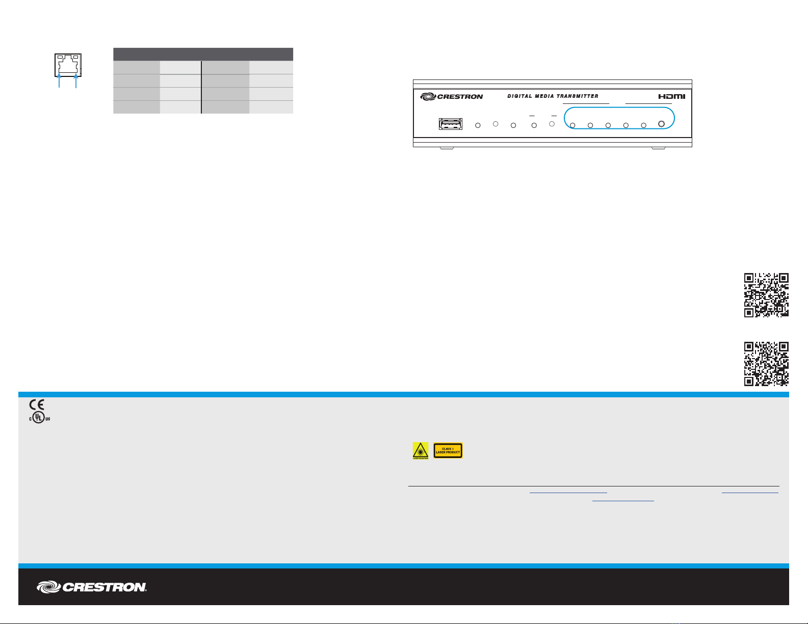
To manually select the desired audio/video input, press the SELECT button on the front panel of
the transmitter until the corresponding LED lights.
Front Panel (DM-TX-401-S Shown)
Pressing the SELECT button in succession cycles from automatic switching (default selection)
through the various available selections in the following order:
• DisplayPort audio and video. The DISPLAY PORT LED lights.
• HDMI audio and video. The HDMI LED lights.
• VGA video with 1/8” audio. The PC LED lights.
• Composite video with dual RCA audio. The VIDEO LED lights.
• None. No input is selected.
After cycling through the above selections, pressing the SELECT button
returns to automatic switching.
DOC. 7550A (2042275) 02.16
Specications subject to change without notice.
LAN Connector Pin Assignments
DO Set the IP Address
The IP address of the transmitter depends on the way the transmitter is congured within the
DigitalMedia 8G™ system:
• If the transmitter connects to a DigitalMedia™ switcher, the transmitter is congured by the
switcher automatically.
• If the transmitter connects to a receiver/room controller, the transmitter uses its own
conguration settings. By default, DHCP (Dynamic Host Conguration Protocol) is enabled.
If assignment of the default IP address to the transmitter is desired, hold down the SETUP
button while the unit boots up. The default IP address overwrites the current setting.
The default IP address of the DM-TX-401-S and DM-TX-401-S2 is 192.168.1.238.
To manually set a different IP address, use the Crestron Toolbox™ application.
DO Select Inputs
By default, automatic switching of inputs is enabled. Automatic switching causes inputs to
switch according to the following priorities:
• Video switching priority: DisplayPort, HDMI, RGB, composite
• Audio switching priority: DisplayPort, HDMI, 1/8" analog, dual RCA analog
The AUTO LED on the front panel of the device lights to indicate that automatic switching is
enabled.
DO Learn More
Visit the website for additional information and the latest rmware updates. To learn
more about this product, use a QR reader application on your mobile device to scan
the QR images.
Crestron Electronics
15 Volvo Drive, Rockleigh, NJ 07647
888.CRESTRON | www.crestron.com
As of the date of manufacture, these products have been tested and found to comply with specications for CE marking.
This product is Listed to applicable UL Standards and requirements by Underwriters Laboratories Inc.
Federal Communications Commission (FCC) Compliance Statement
This device complies with part 15 of the FCC Rules. Operation is subject to the following two conditions:
(1) This device may not cause harmful interference, and (2) this device must accept any interference received, including interference
that may cause undesired operation.
CAUTION:Changes or modications not expressly approved by the manufacturer responsible for compliance could void the
user’s authority to operate the equipment.
NOTE: This equipment has been tested and found to comply with the limits for a Class B digital device, pursuant to part 15 of the
FCC Rules. These limits are designed to provide reasonable protection against harmful interference in a residential installation.
This equipment generates, uses and can radiate radio frequency energy and, if not installed and used in accordance with the
instructions, may cause harmful interference to radio communications. However, there is no guarantee that interference will not
occur in a particular installation.
If this equipment does cause harmful interference to radio or television reception, which can be determined by turning the
equipment off and on, the user is encouraged to try to correct the interference by one or more of the following measures:
• Reorient or relocate the receiving antenna.
• Increase the separation between the equipment and receiver.
• Connect the equipment into an outlet on a circuit different from that to which the receiver is connected.
• Consult the dealer or an experienced radio/TV technician for help.
Industry Canada (IC) Compliance Statement
CAN ICES-3(B)/NMB-3(B)
The products are class 1 laser products. They comply with safety regulations of IEC-60825-1, FDA 21 CFR
1040 11 and FDA 21 CFR 1040 10.
Warning: Visible and invisible laser radiation when open. Avoid direct exposure to beam.
Note: Plug the included dust cap into the optical transceiver when the ber optic cable is unplugged.
The specic patents that cover Crestron products are listed at http://www.crestron.com/legal/patents. The product warranty can be found at www.crestron.com/warranty.
Certain Crestron products contain open source software. For specic information, please visit www.crestron.com/opensource.
Crestron, the Crestron logo, Crestron Toolbox, DigitalMedia, DigitalMedia 8G, and DM are either trademarks or registered trademarks of Crestron Electronics, Inc. in the United States and/or
other countries. HDMI, the HDMI logo, and High Denition Multimedia Interface are either trademarks or registered trademarks of HDMI Licensing LLC in the United States and/or other countries.
UL and the UL logo are either trademarks or registered trademarks of Underwriters Laboratories, Inc. in the United States and/or other countries. Other trademarks, registered trademarks, and
trade names may be used in this document to refer to either the entities claiming the marks and names or their products. Crestron disclaims any proprietary interest in the marks and names of
others. Crestron is not responsible for errors in typography or photography.
This document was written by the Technical Publications department at Crestron.
©2016 Crestron Electronics, Inc.
PIN NUM. SIGNAL PIN NUM. SIGNAL
1TX+ 5N/C
2TX- 6RX-
3RX+ 7N/C
4N/C 8N/C
DM-T X-401-S2
USB HID RESET
DM
LINK SETUP AUTO VIDEO HDMI
DISPLAY
PORT SELECT
DM-TX-401-S
PWR PC
INPUT
Pin 1Pin 8
DM-T X-401-S

This manual suits for next models

2

Other Crestron Transmitter manuals

Crestron QM-TX User manual

Crestron

Crestron QM-TX User manual

Crestron HD-TXCA-4KZ-101 User manual

Crestron

Crestron HD-TXCA-4KZ-101 User manual

Crestron DM-TX-200-C-2G User manual

Crestron

Crestron DM-TX-200-C-2G User manual

Crestron IM-WCVP Quick start guide

Crestron

Crestron IM-WCVP Quick start guide

Crestron DigitalMedia 8G+ DM-TX-201-C Dimensional drawing

Crestron

Crestron DigitalMedia 8G+ DM-TX-201-C Dimensional drawing

Crestron IM-FTCC-B How to use

Crestron

Crestron IM-FTCC-B How to use

Crestron IM-TCCV Quick start guide

Crestron

Crestron IM-TCCV Quick start guide

Crestron DM Lite HD-TX-4KZ-101 User manual

Crestron

Crestron DM Lite HD-TX-4KZ-101 User manual

Crestron DM-TX-4K-202-C User manual

Crestron

Crestron DM-TX-4K-202-C User manual

Crestron DigitalMedia DM-TX-300N User manual

Crestron

Crestron DigitalMedia DM-TX-300N User manual

Crestron HD-TX-4KZ-111-1G User manual

Crestron

Crestron HD-TX-4KZ-111-1G User manual

Crestron DigitalMedia 8G+ DM-TX-4KZ-100-C-1G User manual

Crestron

Crestron DigitalMedia 8G+ DM-TX-4KZ-100-C-1G User manual

Crestron DigitalMedia DMCF-TX-4K-SFP Dimensional drawing

Crestron

Crestron DigitalMedia DMCF-TX-4K-SFP Dimensional drawing

Crestron IM-WCVI User manual

Crestron

Crestron IM-WCVI User manual

Crestron CNIRHT-MM User manual

Crestron

Crestron CNIRHT-MM User manual

Crestron HD-TXC-4KZ-101 User manual

Crestron

Crestron HD-TXC-4KZ-101 User manual

Crestron HD-TXA-4KZ-101 User manual

Crestron

Crestron HD-TXA-4KZ-101 User manual

Crestron DigitalMedia DMF-TX-4K-SFP Dimensional drawing

Crestron

Crestron DigitalMedia DMF-TX-4K-SFP Dimensional drawing

Crestron DigitalMedia 8G+ DM-TX-4KZ-202-C Owner's manual

Crestron

Crestron DigitalMedia 8G+ DM-TX-4KZ-202-C Owner's manual

Crestron DM-TX-201-C User manual

Crestron

Crestron DM-TX-201-C User manual

Crestron DM-TX-200-C-2G Dimensional drawing

Crestron

Crestron DM-TX-200-C-2G Dimensional drawing

Crestron IM-WCC How to use

Crestron

Crestron IM-WCC How to use

Crestron DM-TX-201-S Dimensional drawing

Crestron

Crestron DM-TX-201-S Dimensional drawing

Crestron HD-TX-4KZ-101-1G User manual

Crestron

Crestron HD-TX-4KZ-101-1G User manual

Popular Transmitter manuals by other brands

M-system M3LV instruction manual

M-system

M-system M3LV instruction manual

Moore Industries TIY installation manual

Moore Industries

Moore Industries TIY installation manual

Retekess TR501 user manual

Retekess

Retekess TR501 user manual

CYP IP-7000TX Operation manuals

CYP

CYP IP-7000TX Operation manuals

Geemarc AMPLICALL 110 manual

Geemarc

Geemarc AMPLICALL 110 manual

Interlogix AT1000 Installation & operation

Interlogix

Interlogix AT1000 Installation & operation

KROHNE DR 400 Series Supplementary instructions

KROHNE

KROHNE DR 400 Series Supplementary instructions

Emerson Rosemount 5408 quick start guide

Emerson

Emerson Rosemount 5408 quick start guide

Hokuyo DMS Series instruction manual

Hokuyo

Hokuyo DMS Series instruction manual

GF Signet 8850-3 manual

GF

GF Signet 8850-3 manual

Long Range Systems T74C232 Quick setup & operation

Long Range Systems

Long Range Systems T74C232 Quick setup & operation

FONESTAR AIP-4010 instruction manual

FONESTAR

FONESTAR AIP-4010 instruction manual

Vislink PTX-PRO User and technical manual

Vislink

Vislink PTX-PRO User and technical manual

Avantree BTCK-310 user manual

Avantree

Avantree BTCK-310 user manual

Endress+Hauser Liquisys M CPM 223 operating instructions

Endress+Hauser

Endress+Hauser Liquisys M CPM 223 operating instructions

Altinex Multi Tasker MT103-122 user guide

Altinex

Altinex Multi Tasker MT103-122 user guide

Festo SDAT-MHS SA Series Brief Instruction

Festo

Festo SDAT-MHS SA Series Brief Instruction

Cygnett CY-3-PA2 Setup instructions

Cygnett

Cygnett CY-3-PA2 Setup instructions

manuals.online logo
manuals.online logoBrands
  • About & Mission
  • Contact us
  • Privacy Policy
  • Terms and Conditions

Copyright 2025 Manuals.Online. All Rights Reserved.