quickstart guide
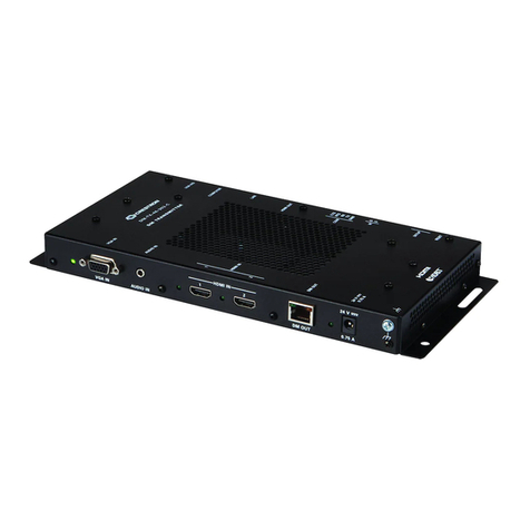
DM-TX-200-C-2G
www.crestron.com
888.273.7876 201.767.3400
Specifications subject to
change without notice.
DM-TX-200-C-2G
QUICKSTART DOC. 7321A (2032811) 12.11
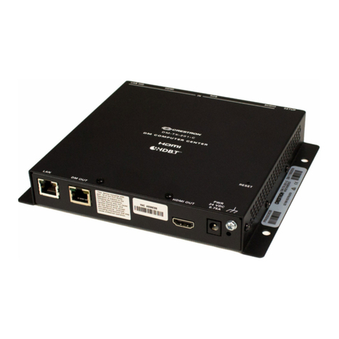
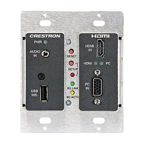
Wall Plate DigitalMedia 8G+™ Transmitter 200
Installation Overview
Installation into Electrical Box
1
1For details, refer to the latest version of the DM-TX-200-C-2G
Operations and Installation Guide, Doc. 7320.
DM-MD8X8
DM-RMC-100-C
COM
HDMI OUT
GND
TX
RX
RTS
CTS
S
G
S
S
1
2
IR
LAN
DM IN
RESET
SETUP
24 V
0.75A MAX
DM-RMC-100-C
DM ROOM CONTROLLER
Ground DM
OUT
24 G
24V
0.7A
Ground DM
OUT
24 G
24V
0.7A
POWER
PACK
DM-TX-200-C-2G Using PoDM Via Connection to DM Switcher
(DM-MD8X8 Shown)
DM-TX-200-C-2G Connection to DM Receiver/Room Controller
(DM-RMC-100-C Shown)—External Power Pack Required
When installing the DM-TX-200-C-2G, verify that the
required wiring has been fed through the electrical box/floor
box (not included) before connecting the rear panel of the
DM-TX-200-C-2G.
DM 8G+™ Output Connection
Connect the DM OUT port of the transmitter to the
DM 8G+
™
input of a DM® switcher, receiver/room controller,
or other DM device. If connecting to a DM switcher, connect
the transmitter to the DM IN port of a DMC-C/DMC-C-DSP
input card of the switcher.
For DM 8G+
™
wiring up to 330 feet (100 meters) between
devices, use any of the following cables (sold separately):
● Crestron® DM-CBL-8G DigitalMedia 8G™ cable
● Crestron DM-CBL DigitalMedia™ cable
● Crestron DM-CBL-D DigitalMedia D cable
● Generic CAT5e (or better) UTP or STP
Power Connection
If the transmitter is not to be powered using PoDM, connect
the 2-pin terminal block to the included power pack.
Ground Connection
Connect the chassis ground lug to earth ground
(building steel).
NOTE: Shielded cable and connectors are recommended
to safeguard against unpredictable environmental
electrical noise which may impact performance at
resolutions above 1080p.
NOTE: Connecting the 24 VDC 2-pin terminal block is
not required if the transmitter is to be powered using
Power over DM (PoDM).
Rear Panel Connections
2
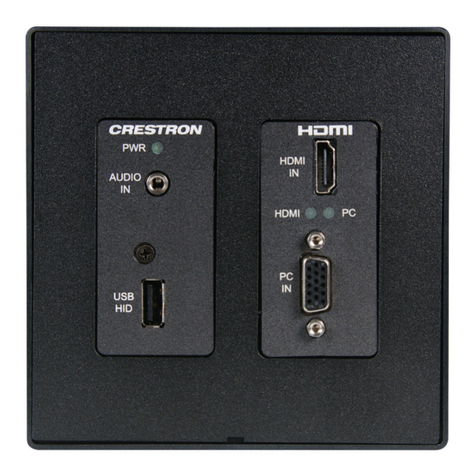
The DM-TX-200-C-2G is designed for installation into a
2-gang electrical box (not included). The DM-TX-200-C-2G
also fits in a 6 inch (153 mm) floor box (not included).
Installation
3
Refer to Section below for information about installing the
DM-TX-200-C-2G into an electrical box (not included). Refer to
Section on the following page for information about installing
the DM-TX-200-C-2G into a floor box (not included).
3A
3B
3A
The DM-TX-200-C-2G can be installed into a 2-gang electrical box
(not included) in a wall, floor, or ceiling. A minimum mounting
depth of 2.5 inches (64 mm) is required.
To install the DM-TX-200-C-2G into an electrical box:
1. Using a Phillips head or straight blade screwdriver, attach the
DM-TX-200-C-2G to the electrical box using the four included
#6-32 x 3/4 inch truss combo head screws (2009211).
2. Attach a decorator style faceplate (not included) to the front
panel of the DM-TX-200-C-2G using four screws (not included).
5
DM-TX-200-C-2G Installation into Electrical Box
2-Gang
Electrical Box
(Not Included)
DM-TX-200-C-2G-W-T (6505823)
or
DM-TX-200-C-2G-B-T (6505824)
#6-32 x 3/4”
Truss Combo
Head Screws (4)
(2009211)
2-Gang Faceplate
with Attachment Screws (4)
(Not Included)
