CYKLOP LIGOTECH LGT 260 User manual

LGT 260
Battery-operated
Hand Tool for Plastic
Strapping
Operating Manual /
Spare Parts

1. SAFETY INSTRUCTION
1.1 Personal Safety
1.2 Work Area Safety
1.3 Power Tool Use And Care
1.4 Battery Tool Use And Care
1.5 Hazards of Incorrect Operation
1.6 Straps Dispenser
1.7 Welding Effects
1.8 Correct Strap Cutting
1.9 Regular Maintenance
2. TECHNICAL PARAMETERS
2.1 Machine Introduction
2.2 Dimensions
2.3 Strap Specification
2.4 Strap Tensioning
2.5 Working Temperature
3. ATTACHMENT
3.1 Battery Specification
3.2 Charger Specification
3.3 One Set of Tool Kit For Free
3.4 Suspension System(optional)
4. MACHINE APPEARANCE AND OPERATING PANEL
5. OPERATION STEPS
5.1 Installation
5.2 Operation Function Description
5.2.1 Operation Panel And Buttons
5.2.2 Basic Settings
5.2.3 Strapping Operation Steps
5.2.4 Operation Methods for Three Modes
5.2.5 Operation Essentials For Three Modes
5.3 Strapping Effect and Adjustment
5.3.1 Strap Welding Effect Judgment
5.3.2 Appropriate Parameter Adjustment
5.3.3 Reference for Tension Force (Unit: N)
6. WIRING DIAGRAM
7. COMMON FAULT INDICATION AND TROUBLESHOOTING
7.1 Machine Fault Code Description
7.2 Common Faults and Troubleshooting
8. REPLANCEMENT OF WEARING PARTS
9. SPARE PARTS LIST
10. EXPLODED VIEW OF SPARE PARTS
2
2
3
3
3
4
4
4
5
5
6
6
6
6
6
6
7
7
7
7
8
10
11
11
12
12
14
16
17
18
19
19
19
20
21
22
22
22
23
24
28
CONTENT
Battery-operated Hand Tool LGT260 for Plastic Strapping User Manual
1

23
1. SAFETY INSTRUCTION
Stay alert, watch what you are doing and use common sense
when operating a power tool. Do not use a power tool while you are
tired or under the influence of drugs, alcohol or medication. A
moment of inattention while operating power tools may result in serious
personal injury.
Use personal protective equipment. Always wear eye protection.
Protective equipment such as dust mask, non-skid safety shoes, hard
hat, or hearing protection used for appropriate conditions will reduce
personal injuries.
Prevent unintentional starting. Ensure the switch is in the off-
position before connecting to power source and/or battery pack,
picking up or carrying the tool.
Carrying power tools with your finger on the switch or
energising power tools that have the switch on invites accidents.
Remove any adjusting key or wrench before turning the power
tool on. A wrench or a key left attached to a rotating part of the power
tool may result in personal injury.
Do not overreach. Keep proper footing and balance at all times.
This enables better control of the power tool in unexpected situations.
Dress properly. Do not wear loose clothing or jewellery. Keep
your hair, clothing and gloves away from moving parts. Loose
clothes, jewellery or long hair can be caught in moving parts.
If devices are provided for the connection of dust extraction
and collection facilities, ensure these are connected and properly
used. Use of dust collection can reduce dust-related hazards.
The operators must be trained strictly and correctly, and read
& understand the operation instructions of the tool correctly. If the
operation instructions are not followed or the straps is placed incorrectly,
the straps will be damaged and the operator will be injured.
Before getting start with the tool, please keep your fingers
away from the tension and cutting area of the tool.
Do not use the bonded straps to carry, drag or suspend the
heavy object, which may cause accidents.
Read all safety warnings and all instructions.
Failure to follow the warnings and instructions may result in electric
shock, fire and/or serious injury.
Save all warnings and instructions for future reference.
The term "power tool" in the warnings refers to your mains-
operated (corded) power tool or battery-operated (cordless) power tool.
1.1 Personal Safety
Do not force the power tool. Use the correct power tool for your application.
The correct power tool will do the job better and safer at the rate for which it was
designed.
Do not use the power tool if the switch does not turn it on and off. Any power
tool that cannot be controlled with the switch is dangerous and must be repaired.
Disconnect the plug from the power source and/or the battery pack from the
power tool before making any adjustments, changing accessories, or storing
power tools. Such preventive safety measures reduce the risk of starting the power tool
accidentally.
Store idle power tools out of the reach of children and do not allow persons
unfamiliar with the power tool or these instructions to operate the power tool.
Power tools are dangerous in the hands of untrained users.
Maintain power tools. Check for misalignment or binding of moving parts,
breakage of parts and any other condition that may affect the power tool's
operation. If damaged, have the power tool repaired before use. Many accidents are
caused by poorly maintained power tools.
Use the power tool and its accessories and tool bits etc. in accordance with
these instructions, taking into account the working conditions and the work to be
performed. Use of the power tool for operations different from those intended could
result in a hazardous situation.
1.2 Work Area Safety
Keep work area clean and well lit. Cluttered or dark areas invite accidents.
Do not operate power tools in explosive atmospheres, such as in the
presence of flammable liquids, gases or dust. Power tools create sparks which may
ignite the dust or fumes.
Keep children and bystanders away while operating a power tool. Distractions
can cause you to lose control.
Do not operate the tool in a narrow space.
1.3 Power Tool Use And Care
Environmental Protection. Please don't discard or burn the waste batteries at will,
causing environmental pollution. If you don't know how to deal with it, please consult the
supplier. Be sure to use the original battery to ensure safety.
Do not disassemble the battery. Please store the battery in a dry and frost
resistant room. Storage temperature should not be higher than 50℃, please keep dry all
the time.
Do not charge the waste batteries. If you find that the battery charging is abnormal,
please do not charge it by force and replace it with a new one to avoid accidents.
Recharge only with the charger specified by the manufacturer. A charger that is
suitable for one type of battery pack may create a risk of fire when used with another battery pack.
1.4 Battery Tool Use And Care
Battery-operated Hand Tool LGT260 for Plastic Strapping User Manual Battery-operated Hand Tool LGT260 for Plastic Strapping User Manual

45
Use power tools only with specifically designated battery packs. Use of any
other battery packs may create a risk of injury and fire.
When battery pack is not in use, keep it away from other metal objects, like
paper clips, coins, keys, nails, screws or other small metal objects, that can make
a connection from one terminal to another. Shorting the battery terminals together
may cause burns or a fire.
Under abusive conditions, liquid may be ejected from the battery; avoid contact.
If contact accidentally occurs, flush with water. If liquid contacts eyes, additionally seek
medical help. Liquid ejected from the battery may cause irritation or burns.
Incorrect operation, excessive tension, improper use of packing straps,
sudden loss of tension force due to loading of sharp objects, or breakage of straps
may eventually lead to:
The operator falling down as a result of out of balance.
Personal harm as a result of the tool and the strap whipping out to the operator quickly.
1.5 Hazards of Incorrect Operation
a. If the load object is sharp, please add edge protection between the strap and the object.
b. Please wrap the packing straps around the object correctly.
In the process of operation, the operator should stand beside the tool and the strap,
instead of in front and back of the tool and the strap. If the operator operates the tool by
standing in a straight-line position with the tool, he may be injured by the tool or the strap
that strikes forward or backward towards him due to improper operation. Keep away from
bystanders during operation. Please use a strap of qualified quality recommended in this
manual. A qualified strap shall have suitable width, thickness and strength. Unqualified
straps may result in strap breakage during strap tensioning, causing hazards.
Attention:
1.6 Straps Dispenser
Please use professional straps dispenser to work with the tool. After finished
the operation, please fold the end of the strap into the straps dispenser.
When it is found that the straps welding joint is unqualified(refer to 5.3 for the
welding joint standard), please cut off the strap and operate again.
Unqualified strap welding may lead to unsecure strapping, which may cause
serious damage during shipping process, bringing a safety hazard.
1.7 Welding Effects
Please cut off the strap with a suitable cutting tool and ensure a safe distance
between the strap and the operator. Do not stand in a same straight line as the strap,
and stay away from the loose direction of the strap, to prevent the operator from being
injured by the bounced strap due to sudden breakage of the strap.
Please use professional tools for cutting straps. Hammers, pliers, hacksaws,
axes, etc. are not allowed.
1.8 Correct Strap Cutting
Have your power tool serviced by a qualified repair person using only
identical replacement parts. This will ensure that the safety of the power tool is
maintained;
Regularly maintain the tool to keep it in a good working condition;
Regularly check for broken or worn parts. If there are broken or worn parts,
please replace the parts in time before using it;
It is recommended to clean the machine regularly (every day) if it is used in a
dirty environment. Remove impurities such as debris in the tensioning and welding
areas of the tool with an air gun(or other dust extraction tool), and observe it with naked
eyes at the same time. If the tool is obviously damaged, please repair it and replace parts
in time;
The battery needs to be charged every six months if it is not used in a long
time;
Most parts of the tool need to be replaced and repaired when the number of
strapping cycles reaches more than 100,000 to avoid personal injury caused by
tool failure;
Please consult the supplier if you need to purchase spare and accessory
parts;
Do not modify the strapping tool without permission, otherwise it may cause
personal injuries.
1.9 Regular Maintenance
Battery-operated Hand Tool LGT260 for Plastic Strapping User Manual Battery-operated Hand Tool LGT260 for Plastic Strapping User Manual

67
LGT260 series electric battery powered strapping tool has been improved greatly in
functions, performance and appearance after continuous tests and improvements by our
R&D team. It over performs competitors' similar tool in quality. Theoretically, up to 700
strapping cycles can be achieved for a battery charging, the maximum tension force can
reach 2800N (the direct tension force of strap tension wheel can reach 4200N), and the
welding time is as short as 1s.
Working modes: Fully Automatic (AUT), Semi-Automatic (SEM), Manual (MAN).
2.1 Machine Introduction
2.3 Strap Specification
Strap material: Smooth or Embossed PET(polyester) or PP (polypropylene)strap.
Strap width: 13mm-16mm; Strap thickness: 0.5-1.2mm
Please choose a strap with an appropriate size according to the strapping tool you
purchased.
2.4 Strap Tensioning
Tension: 400N-2800N(adjustable, the tension force of the tension wheel can reach 4200N).
Tightening speed: 100-200mm/s.
Welding strength: About 75-80% of the strength of PET Strap. (depending on the quality
of the straps)
The ambient air temperature is between 5℃ and 45 .
The optimum operating temperature is between 15℃ and 20℃.
℃
2.5 Working Temperature
Standard Chargers:
Input:
Output:
100-240V, ~50/60Hz 1.5A
16.8V 3.5A, 21V 3.5A
Please use the accessories/parts and maintenance tools required in this operation
manual. It may cause hurt if you using the unfit accessories/parts/maintenance tools.
3.1 Battery Specification
If you need to purchase the battery, contact your local supplier, please refer to the
following battery parameters and specifications:
Battery type: lithium battery
Voltage: 18V
Capacity: 5.0Ah
3.2 Charger Specification
Charging time:
Lithium batteries 5.0A/h, about 90 minutes.
3.3 One Set of Tool Kit For Free
Battery-operated Hand Tool LGT260 for Plastic Strapping User Manual Battery-operated Hand Tool LGT260 for Plastic Strapping User Manual
2. TECHNICAL PARAMETERS
2.2 Dimensions
Length: 335mm
Width: 145mm
Height: 145mm
Weight (without battery
& charger): 3.5kg
Battery weight: 0.62kg
335mm
145mm
145mm
3. ATTACHMENT

Battery-operated Hand Tool LGT260 for Plastic Strapping User Manual
89
Battery-operated Hand Tool LGT260 for Plastic Strapping User Manual
Figure 1: Selection 1 of suspension position during operation
Figure 2: Selection 2 of suspension position during operation
3.4 Suspension System(optional)
Q-2062
T023

10 11
Battery-operated Hand Tool LGT260 for Plastic Strapping User Manual Battery-operated Hand Tool LGT260 for Plastic Strapping User Manual
Please don't expose the tool in the rain or wet environment!
For the sake of safety, the battery is not charged full when delivered.
Please charge the battery before use. Please refer to the attached battery charger
manual.
Installation/Disassembly/Charging of battery:
The battery should be disassembled and assembled following the direction shown
in the below figures. When removing the battery, press the red button and move it out.
When the battery is inserted, the battery status will be displayed for a short time.
The battery power status is displayed by the charger indicator lights:
Flashing green light: it means the battery is being charged
Green light on: it means the battery on the charger is fully charged
5.1 Installation
Battery Installation:
Take out the lithium battery in the
packing box and install it as shown
in the figure on the right. When the
battery is inserted, the power
status light will be displayed for a
short time.
Battery Disassembly:
Remove the battery following the
direction shown in the figure.
When removing the battery, move
it out while pressing and holding
the red button, as shown in the
right figure.
5. OPERATION STEPS
Battery Base
Slot
Insert
the
battery
2.Pull
the
battery
out
1. Press and hold the red button
Normal Working
The battery is low, please charge it
Machine failure, please power it off and check
Work Completion
Light Indicates
Blue Light
Red Light Flash
Red Light ON
Purple Light ON
4. MACHINE APPEARANCE AND OPERATING PANEL
Model
Mechanical
Cover
Control Panel &
Display Screen
Button 1:
Tension
Button
Strap
Tension
Area
Strap
Welding
Area
Battery Power
Indicator
Rocker lever:
To Lift the Tension
Wheel / for
Emergency Stop
Lithium
Battery
Button 2:
Welding
Button

12 13
Battery-operated Hand Tool LGT260 for Plastic Strapping User Manual Battery-operated Hand Tool LGT260 for Plastic Strapping User Manual
Mode selection(MODE) and working status indicator:
Operation mode selector (MODE):
There are three operation modes: Manual(MAN), Semi-
automatic(SEM) and Fully automatic(AUT).
The corresponding indicator light will be on when a mode
is selected, and indicator lights of different colors mean
different working status.
Status indicator lights:
Blue light always-on: means the tool is normal, standby;
Red light flashing: means insufficient power, indicating
the battery has to be charged;
Red light always-on: means tool failure, please power it
off and check;
Purple light on for a short time: indicates completion of
the packing work
Battery indicator: Displays the remaining battery capacity
(all light on means the battery full charged.)
Tension force setting(SET):
Levels 1-9: 400N-2800N
Welding time setting(INC&DEC):
Used to set a welding time, INC is to increase time,
and DEC to shorten time, interval value: 0.5-3.5 seconds.
Tensioning mode selection:
Normal Mode H: The blue indicator light is on;
Soft Mode L: The yellow indicator light is on.
Buttons:
Button 1: Tension Button
Button 2: Welding Button
Yellow
Light On:
Soft
Mode L
Tension
Mode
Indicator
Blue
Light On:
Normal
Mode H
Battery
Indicator
Mode
Selector
Tension
Strength
Welding
Time
Rocker lever:
Holding up the rocker lever, you can lift the tension wheel;
retract the strap or stop the tool in an emergency.
Battery Charging:
Insert the battery to be charged
into the charger slot and plug it
into a power supply, as shown in
the figure on the right.
Insufficient battery power may lead to insufficient welding of the packing straps
Please cut off the strap if the strap welding is not enough!
The battery must be charged before using the tool again.
Warning:
Start preparation:
1. Operation panel unlocking and locking:
Plug in the power supply (battery), and the tool is in the locking state, at this time
any button on the operation panel is invalid.
Unlocking Method for the Operation Panel: Press the button DEC (for about 2s),
and then press the Welding button to unlock it after hearing a sound of Beep.
After parameters are set, you can also press the button DEC for 2s, and then press
the Welding button to lock the operation panel after hearing a sound of Beep.
Note: The tool will enter the locking state again if no operation is performed
within 30s after the tool is unlocked.
2. Waking-up from the sleep state:
The tool will changes to the sleep mode if no operation is carried out within 120s
after the tool is unlocked, and all the indicator lights go out. All buttons will be invalid,
except the button Tensioning A1. To wake up the tool, short press the button Tensioning
A1 to restore it to the standby mode.
At this time, the machine can work normally. If it is necessary to modify the
previously set parameters, please refer to the "Operation panel unlocking", unlocking
the operation panel and then modifying the parameters.
5.2 Operation Function Description
5.2.1 Operation Panel And Buttons

14 15
Welding time
setting
(INC&DEC)
Operation panel
locking (not in
the sleep state)
Waking up of the
tool from the
sleep state
Soft Mode (L- -):
Tension range: 400N-1600N
Level: 1-9
Note: This mode is used when objects to
be strapped are required to be strapped
relatively loosely (or when a PP strap is
used).
When setting the welding time, short press the button INC to increase the
welding time, and short press the button DEC to decrease the welding time
(One press means an increase or decrease of 0.1 seconds, and the value
display interval is 0.5-3.5 seconds.)
The tool will automatically lock its operation panel if no-operation status has
lasted for 30 seconds. Pressing any button on the operation panel will not
work at this time, that is, settings cannot be changed, but the tool can work
normally. It is unnecessary to unlock it unless it is necessary to change the
settings.
An unlocking operation is required before parameter settings are changed
each time.
Unlocking method: Long press the button DEC (for about 2s), and then press
the button Welding “2” after hearing a sound of Beep.
The tool will changes to sleep mode if no-operation status has lasted for 120
seconds, and all the indicator lights go out. All buttons will be invalid, except
the button Tensioning “1”. To wake up the tool, short press the button
Tensioning “1” to restore it to the standby mode.
You can check six digits:
After unlocking the operation panel, long press the button MODE for about 5
seconds, and the display screen will display three digits, ones place, tens
place, and hundreds place (a decimal point at the side of the ones place) in
the first page, and thousands place, ten thousands place and hundred
thousands place in the second page.
You can switch the pages in a circular manner by short pressing the button MODE.
Exit and return to the main display screen by pressing the button INC or any
other button.
First Page Second Page
Ones
Place
Tens
Place
Hundreds
Place
Thousands
Place
Ten
Thousands
Place
Hundred
Thousands
Place
Check “Cycle
Counter” (to
readout the
accumulative
strappings has
already
accomplished by
the tool): six
digits displayed
on the screen
Battery-operated Hand Tool LGT260 for Plastic Strapping User Manual Battery-operated Hand Tool LGT260 for Plastic Strapping User Manual
5.2.2 Basic Settings
Mode
selection
(MODE)
Tension force
setting (SET)
After the operation panel
unlocked, you can cycle to
select a mode you need by
short pressing the button
MODE.
Normal Mode (H- -):
Tension force range: 400-2800N (adjustable,
the tension force of the tension wheel can
reach 4200N.)
Level: 1-9
Instruction: This mode is used when objects
to be strapped are required to be strapped
relatively tightly (or when a PET strap is used).
Note: in the Normal Mode, please adjust the
tension force for your desired one by
increasing the tension force from the
minimum in sequence; and avoid the
maximum Level, as the tension force at this
Level is the strongest, a strap can't bear it,
which will cause personal injuries of the
operator.
Manual mode (MAN): Tensioning function and
welding function will be operated separately.
Press and hold the button Tensioning “1” until
the set tension force is reached and then press
the button Welding “2” for manual strap
welding & cutting.
Semi automatic mode (SEM): Long press the
button Tensioning “1”, and the straps will be
tensioned and welded one time.(The tension
wheel will stop rotating if the button Tensioning
“1” is released during the tensioning process,
and at this time, the tool will start welding and
cutting off the strap if the button Welding “2” is
pressed.)
Fully automatic mode (AUT): Short press the
button Tensioning “1”, and the machine will
automatically tension, weld and cut off the
strap. Under this mode: The strap will be
tensioned automatically, and will be welded
and cut off automatically when the tension
grade reaches the set one.
After the operation panel
unlocked:
◎Adjust the strap tension
range (Level 1-9) by short
pressing the button SET.
The larger the number is,
the stronger the tension
force will be; and the weaker
on the contrary. (Level 1
stands for the minimum
tension force, and Level 9
for the maximum.)
◎The default factory
setting of the machine is
Normal Mode H. Long
press the button SET on
the operation panel, and
“H - -" on the digital
display will flash for 3
times, which means the
tool enters the Normal
Mode. Then long press
the button SET on the
panel, and “L - -" on the
digital display will flash
for 3 times, which means
the tool enters the Soft
Mode.

Battery-operated Hand Tool LGT260 for Plastic Strapping User Manual
16 17
Battery-operated Hand Tool LGT260 for Plastic Strapping User Manual
Object(simulation)
d.Weld and cut off the strap:
Weld and cut off the strap to
finish the strapping operation
by referring to the Method for
Basic Settings.
The purple indicator light will be
on during the welding process.
Strap Welding & Cutting Completed
Remarks:
5.2.4 Operation Methods for Three Modes
e. Remove the machine and
complete the operation:
After the welding is finished,
the buzzer rings for 3 seconds
and stops, indicating that the
strap welding and cutting work
is completed. At this time, you
can remove the machine by
lifting the rocker lever and
moving the tool rightward and
wait for a next operation.
Manual Mode (MAN):
Semi-Automatic(SEM):
1. In the Automatic (AUT) Mode, only Steps a, b, c, e are required.
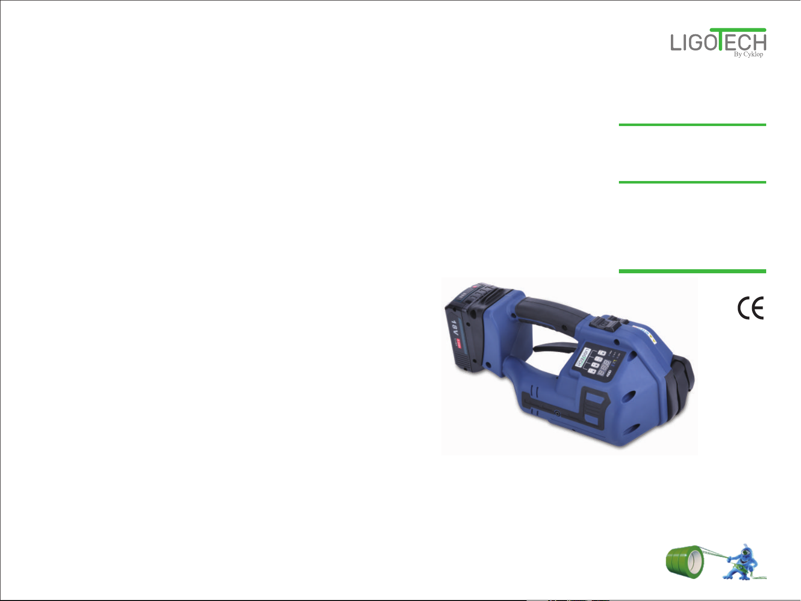
2. Remove the battery and then install it again, if the tool fails
to work normally due to misoperation or other reasons.
3. When the strap is stuck by the machine, the battery must be
pulled out first, then cut off the strap, remove the Left Guard
(side cover), and then remove the strap.
4.The tension protection function will start by pressing the
button Tensioning “1” continuously for 8 times, and at this time,
the protection function can be cancelled by lifting the rocker
lever once.
5. Note: If the rocker lever is lifted immediately after welding,
the machine will give rapid sound alarms for 5 seconds due to
a lack of cooling time.
Long press the button Tensioning “1” until the set tension level is
reached, and the machine will stop automatically. Then press the
button Welding “2”, and strap welding and cutting will be finished after
three short sounds of "Beep", and at this time, hold the rocker lever to
retract the strap and remove the tool.
Long press the button Tensioning “1” until the set tension level is
reached, and the machine will automatically weld and cut off the strap.
The strap welding will be finished after three short sounds of "Beep",
and at this time, hold the rocker lever to retract the strap and remove
the machine.
Fully Automatic(AUT): Short press the button Tensioning “1” until the set tension level is reached,
and the tool will automatically weld and cut off the strap. The strap welding
will be finished after three short sounds of "Beep", and at this time, hold the
rocker lever to retract the strap and remove the machine.
a. wrap the PP/PET straps around
the object to be packed:
The operator faces the tool, holding
the machine in his right hand, and the
machine is on the right side of the
operator. Place the strap around the
object to be strapped in the order of
upper side->front side->lower side-
>back side, as shown in the figure.
Warning: Please keep the
PP/PET strap away from oil,
grease and other dirt when
welding it, as a dirty strap cannot
be welded well.
5.2.3 Strapping Operation Steps
b. Put the straps into the tool:
After feeding the strap around
the object to be strapped
properly, lift the rocker lever of
the machine with your right
hand, and insert the parallel
overlaid straps into the tool
smoothly with your left hand, and
then release the rocker level.
Note: Please tension the
strap around the object as
much as possible and then
insert it into the tool, which can
reduce the strap tensioning
time of the tool, avoiding
wasting electric energy.
c. Tension the strap:
Tension the strap to finish the
strapping operation by referring
to the Method for Basic Settings.
Note:
Manual(MAN) and Semi-
Automatic(SEM) Mode: Press
the tension button “1” until the
indicator light shows purple, and the
tension protection does not affect
the next-step operation.
Automatic(AUT) Mode:
Press the tension button in a short
time and release.
Warning: Keep the movement
of the tool in balance during the
tensioning process. Lift the
rocker lever to stop working
when an emergency stop is
required during the tensioning
process. Therefore, do not
block the movement direction
of the strapping tool.
Object(simulation)
Correct Feeding Direction
Object(simulation)
Wrong Feeding Direction
Object(simulation) Object(simulation)
Proper Length of Strap Left Excessive Length of Strap Left
Object (simulation)
Tension Completed

Battery-operated Hand Tool LGT260 for Plastic Strapping User Manual
18 19
Battery-operated Hand Tool LGT260 for Plastic Strapping User Manual
It is necessary to control the welding effects after each strapping, which can be
judged by visual inspection.
There are the following three situations, as shown in the figure:
5.3 Strapping Effect and Adjustment
5.3.1 Strap Welding Effect Judgment
Welding time too long:
If the welding time is too long, it will lead to strap
overheating. Excessive molten material forced out on
both sides of the strap in the strap welding area
indicates welding time too long.
Warning: The strap with excessive welding must be
cut off, adjust the welding time and operate the tool again.
Welding time & effect perfect:
The whole width of the strap is welded fully in the strap
welding area, and the welding length is about 19mm. A
little molten material is forced out on both sides,
indicating that the welding time is appropriate.
Welding time too short:
In the strap welding area, there is no molten material
forced out on both sides or only a little forced out on
one side, and the whole strap width is not welded, all
of which indicates insufficient welding time and
insufficient welding.
Warning: The strap with insufficient welding must be
cut off, adjust the welding time and operate the tool again.
5.3.2 Appropriate Parameter Adjustment
When the strapping effect is too loose or too tensioned, and the welding time is not
appropriate, please adjust the parameters following the setting method to keep the
strapping effect in the best condition. The tool cannot be used grudgingly, especially
when the welding time deviation is too large, which may cause strap off, causing harm to
the operator or products.
Note: If it is necessary to change the strap specifications, please make the
following adjustments to the tool to adapt to the strap of different specifications:
1. According to the thickness of straps:
It is necessary to change the spring of the cutter to achieve strap cutting effects,
especially for thinner straps such as PP straps. (The supplied spring is included in the
toolkit supplied with the tool.)
2. According to the width of straps:
To switch the width of straps, it is necessary to replace the strap guides (included)
in the tensioning area in the front of the tool and the welding area in the back of the tool.
5.2.5 Operation Essentials For Three Modes
Item
a. Install the battery
b. Strapping
c.Idle for 30 seconds
d.Idle for 120 seconds
e.Red light flashing
Manual
Mode(MAN)
Semi-Automatic
Mode(SEM)
Full-Automatic
Mode(AUT)
1. Inset the charged battery into the battery slot, completed after a sound
of “Click”.
2. The display lights are ON, displaying all the previously set data, and
the blue light is always on, going to the standby mode.
It indicates the power is low, so replace the battery or remove the battery
and charge it.
1. Place the strap
around the object to
be strapped.
2. Long press the
button Tensioning “1”
for strap retraction until
your desired tension is
reached.
3. Press the button
Welding “2” for friction
welding process, the
purple light short on,
and one long sound of
“Beep”, the strapping
finished.
4. An emergency stop
or strap retraction can
be achieved by lifting
the rocker lever during
the strapping process.
5. The machine goes
into the standby mode
(the blue light always
on).
1. Place the strap
around the object to
be strapped.
2. Long press the
button Tensioning“1”
for strap retraction until
the set tension is
reached, and then the
machine will carry out
friction welding process
automatically, the
purple light short on,
and three short sounds
of “Beep”, the strapping
finished.
3. An emergency stop
or strap retraction can
be achieved by lifting
the rocker lever during
the strapping process.
4. The machine goes
into the standby mode
(the blue light always
on).
1. Place the strap
around the object to be
strapped.
2. Short press (releasing
immediately) the button
Tensioning “1” for strap
retraction until the set
tension is reached, and
then the tool will carry
out friction welding
process automatically,
the purple light short on,
and three short sounds
of “Beep”, the strapping
finished.
3. An emergency stop
or strap retraction can
be achieved by lifting
the rocker lever during
the strapping process.
4. The machine goes
into the standby mode
(the blue light always
on).
1. The operation panel of the machine will be locked with a sound of
"Beep" after 30 seconds without any operation.
2. Long press the button DEC (for about 2 seconds), and you can unlock
it by pressing the button Welding “2” after a sound of "Beep". (If it is not
necessary to set parameters, it is not necessary to unlock the panel,
because the machine can work in this case).
3. Strapping (the same as Item b).
1. The machine will go into the sleep state with a sound of "Beep" after
120 seconds without any operation. Any button/key is invalid, except the
button Tensioning “1”, in this case;
2. The machine can be wakened up by pressing the button Tensioning
“1”, and then enter the state of step a;
3. Strapping (the same as step b).

Battery-operated Hand Tool LGT260 for Plastic Strapping User Manual
21
20
Battery-operated Hand Tool LGT260 for Plastic Strapping User Manual
6.WIRING DIAGRAM
1234
1 2 3 4 5 6
1 2 3 4 5
6
7
8
9
10
7 8
Tensioning
Motor Hall Line
Reset
Microswitch
Welding
Microswitch
Straps Rewind
Microswitch
Tensioning
Microswitch
Negative
Pole of
Battery
(Black)
Positive
Pole
of Battery
(Red)
Tensioning
Motor
Welding
Motor
Welding Motor Hall Line
Display Board
Main Board
400
550
700
850
1000
1150
1300
1450
1600
1
2
3
4
5
6
7
8
9
400
900
1400
1900
2400
2900
3400
3800
4200
5.3.3 Reference for Tension Force from Tension Wheel ( Unit: N)
Gear Normal mode (H) Flexible mode (L)

Battery-operated Hand Tool LGT260 for Plastic Strapping User Manual
23
22
Battery-operated Hand Tool LGT260 for Plastic Strapping User Manual
Note: please remove the battery before repairing the machine each time.
Q-0010
Q-2040
Q-5027
Q-6006
Q-5020
Q-A002
Q-A001
Description of
Wearing Parts
8. REPLANCEMENT OF WEARING PARTS
Cutter(Q-0078)
Tension Wheel
(Q-0010)
Welding Toothed
Plate(Q-A001)
Tension Toothed
Plate(Q-2040)
Replacement Steps
First remove the left shield (side cover), moving it away, then remove the
screw on the cutter and move it away, take out the cutter and keep the
cutter spring properly. Replace the cutter, install it in the reverse order.
Remove the lower welding toothed plate by removing the fixing screw of the
lower welding toothed plate; replace the toothed plate, then install it in the
reverse order.
Remove the screw fixing the toothed plate on the base, lift the rocker lever,
take out the toothed plate for replacement, and then install it in the reverse
order.
First remove the left shield (side cover), moving it away, take out the tension
wheel, and then take out the two bearings in the tension wheel; replace the
tension wheel, and then install it in the reverse order.
E0.2
E0.3
E0.4
E0.5
E0.6
E1.0
E1.1
7.1 Machine Fault Code Description
Over-current protection
Tension motor timeout fault (tension function not completed after more than 10 seconds)
Short circuit fault of tension motor
Tension motor Hall abnormal/abnormal current induction of tension motor
Short circuit fault of welding motor
Welding motor Hall abnormal/abnormal current induction of welding motor
A motor is still outputting torque when the speed of the motor is 0 rpm/motor rotor locked
In case of any of the above faults, you can remove it by pressing any button and enter the
standby mode. If it can't return to normal, please contact the supplier for solutions.
7.2 Common Faults and Troubleshooting
Abnormal Situation Possible Causes Solution
The tool
doesn't work
The strap can not be
retracted or pulled
The machine slides
forward when
tensioning strap
Tension motor idles
Incomplete welding
Operation completed
but strap broken
Operation completed,
but failed to remove
the tool
Uneasily strap cutting
The battery is not installed
properly or short of power
Tension micro switch wire falling off
Failure of tension micro switch
Short of power possible
Grade problem
Soft mode(L)
Strap debris accumulated on
the anti-sliding toothed plate
The anti-sliding toothed plate worn
Strap debris accumulated in the
surface toothed grooves of the
tension wheel
The tension wheel worn
The strap too thin
Welding time too long or too short
Strap debris accumulated on
the friction toothed plate
The friction toothed plate worn
Strap width not adjusted properly
Welding time too long or too short
The items to be strapped having
excessive tension
The tension wheel cannot be
lifted up
Strap retraction function failure
The cutter worn or the cutter
spring losing its elasticity
Reinstall the battery or charge it
Re-weld/re-connect the wires
Replace the strap tension micro switch
Check the battery power, if it is low,
charge it and then use it
Increase the tension grade
Switch the mode to be Normal Mode(H)
Remove debris with a drill pin in the
tool kit
Replace the anti-sliding toothed plate
Remove debris with a drill pin in the
tool kit
Replace the tension wheel
Add an appropriate gasket under the
anti-sliding toothed plate
Make adjustments by referring to 5.3
Strapping Effect and Adjustment
Remove debris with a drill pin in the
tool kit
Replace the friction toothed plate
Adjust the strap width limit block
(refer to 5.3.2)
Make adjustments by referring to 5.3
Strapping Effect and Adjustment
Check if the cooling time is too short
Check if it is stuck by residual strap
Check if the strap retraction switch is faulty
Replace the cutter or the cutter spring
7. COMMON FAULT INDICATION AND TROUBLESHOOTING

Battery-operated Hand Tool LGT260 for Plastic Strapping User Manual
25
24
Battery-operated Hand Tool LGT260 for Plastic Strapping User Manual
Continued
Table 1
9. SPARE PARTS LIST
Q-0004
Q-0005
Q-0006
Q-0007
Q-0008
Q-0010
Q-0011
Q-0019
Q-0020B
Q-0026
Q-0027
Q-0028
Q-0031
Q-0032
Q-0040
Q-0041
Q-0042
Q-0052
Q-0053
Q-0077
Q-0078
Q-0079
Q-0080
Q-0098
Q-0099
Q-0122
Q-0123
Q-0125
Q-2021
Q-2022
Q-2023
Q-2024
Q-2025-1
Q-2040
1
3
3
1
1
1
3
1
1
1
1
1
1
3
1
1
1
1
1
1
1
1
1
1
1
2
2
5
1
1
1
1
1
1
2011000203
2010096287
2010096288
2010096289
2011000194
2010096290
2010096291
2010100170
2015000503
2011000198
2010100174
2010100175
2011000201
2011000202
2011000204
2010900064
2010900065
2011000186
2011000187
1030126719
2011000213
2011000214
1030126721
1030126722
1030126723
2010096315
2010096316
1030126726
2011000225
2011000226
2060074516
2011000227
2015000714
2011000237
Q-2041
Q-2042
Q-2051
T1099
Q-2061
Q-2063
Q-2064
Q-2L006
Q-3S023
Q-5005
Q-5006
Q-5008B
Q-5009A
Q-5010
Q-5011
Q-5013
Q-5014
Q-5014-1
Q-5016
Q-5017A
Q-5018
Q-5019
Q-5020
Q-5021
Q-5027
Q-5028
Q-5031
Q-5033
Q-5034
Q-5035
Q-5037
Q-5039
Q-5041
Q-6003
Q-6004
Q-6005
1
1
3
1
1
1
1
1
1
1
1
1
1
1
1
1
1
1
1
1
1
1
1
1
1
1
1
1
1
1
1
1
1
1
1
1
2010100168
2011000235
1021605521
1020608828
2015000107
1030144544
1030144545
1030144537
2015000512
1030127954
1030130272
2015000689
2015000583
2015000113
2010100240
2015000171
2015000116
2015000715
2010900075
2010100556
2015000152
2015000153
2010900077
2010900078
2015000155
2015000121
2015000118
2015000114
2015000150
1030128219
1021606068
2015000172
2015000117
1030127946
1030127947
1030127948
No. Part Code Description Qty
Base rocker pin
Planet carrier 2 pin
Planetary carrier 2 gear
Planetary carrier 2
Chute spring retaining pin
Tension pulley
Tensioning wheel planetary gear
Welding spring retainer sleeve-1
Welding spring retainer sleeve-2
Handle pin
Sector gear
Cam disc
Stop ejector pin shaft
Pin 1
Fixing pin of welding spring
13mm behind the guide belt
13mm in front of guide belt
13mm behind the guide belt
13mm in front of guide belt
Welding limit spring
Cutter
Cutter bushing
Cutter compression spring
Welding fixed frame return spring
Ejector shaft spring
Metal insert 1
Metal insert 2
Welding button spring
Fusion chute
Welding gear block
Connecting rod
Briquette
Eccentric shaft
Tighten the lower gear plate
Base rocker
Fusion drive pin
Microswitch zippy (right outlet)
The micro switch
Reset ejector shaft
Housing 2
Housing 1
Plastic part shield
Tensioning motor mounting plate
Bracket
Handle
Ratchet 19
Gear A
Double gear
Welding mounting base
Welding motor mounting plate
Large synchronous pulley
Timing pulley - 1
Reset lever
Blocking rod A
pin shaft
Fixing pin of welding spring
Belt guide rod
Fusion skeleton
Guide pin
Base guard
Cam
Tensioning motor gear
Tensioning motor
Handle return spring
Circuit board
Pin 1
Internal gear
Fusion button
Pull button
Mounting frame

26
Battery-operated Hand Tool LGT260 for Plastic Strapping User Manual
Continued
Battery-operated Hand Tool LGT260 for Plastic Strapping User Manual
27
Continued
Q-6006
Q-6007
Q-6008A
Q-6008B
Q-6020A
Q-6022A
Q-6023A
Q-6024A
Q-6038
Q-6S001
Q-6S002
Q-6S012
Q-A001
Q-A002
Q-A003
Q-5014-2
Q-A005
Q-A006
Q-A007
Q-A008
Q-T007
Q-T009
Q-T014
Q-T015
Q-T016
Q-T019B
Q-T026B
Q-T027B
Q-T046
Q-T050
Q-T206
Q-T208B
Q-T208C
Q-T212B
Q-T215
Q-T218
1
1
1
1
1
1
1
1
1
1
1
1
1
1
4
1
1
8
1
8
2
1
1
1
1
2
3
3
1
1
2
6
1
13
4
1
1030127949
1030129667
1030130958
1030130959
2010100686
3020008988
3020007405
1020103099
1030129657
1030131246
1030131247
2011000261
2010013130
2010013147
1030102658
2010100687
2010020285
1030131007
1030119859
1030128251
1021402954
1021403742
1030126733
1030126734
1030126735
1030131008
1030131009
1030131010
1020609694
1020609985
1030118355
1030131012
1030131013
1030131014
1021401289
1030128552
Q-T219B
Q-T223B
Q-T224
Q-T238A
Q-T235
Q-T236
Q-T501B
Q-T502
Q-T503
Q-T504
Q-T506B
Q-T508
Q-T511
Q-T601A
Q-T602A
Q-T607B
Q-T608
Q-T611
Q-T612
T021B
T1079B
T1083B
T1089B
T1094
T1099
T1104A
T501
T502
T503
T504
T611
T631
TD34
A72B
2
1
1
1
1
1
5
1
1
1
3
4
1
1
1
2
1
1
1
7
1
7
4
8
1
1
1
3
1
2
2
2
2
1
1030131015
1021510270
1021400502
1021404631
1030129251
1030129259
1030131016
1021401167
1021404630
1030128225
1030131017
1030128553
1030126753
1030215287
1021406733
1030131018
1030128522
1030130369
1030130370
1030131019
1030131020
1030131021
1030131022
1030100433
1020608828
1021403753
1021400712
1021401563
1021401582
1021401565
1031012719
1030126918
1030116838
1030131024
No. Part Code Description Qty No. Part Code Description Qty
Left hood
Support frame
Upper cover of circuit board
Lower cover of circuit board
Toggle lever A
Bushing A
Welding motor gear A
Welding motor A
Limit circlip
Left housing
Right housing
Body base
Welding lower gear
Welding lower gear plate fixing screw
Circlip Φ4
Belt pulley gasket
Sliding gear block baffle 1
Self tapping screw M2.5×6
Nut M4
Hexagon socket pan head screw M3*6
Bearing 61807-2Z
Needle bearing HK1015
Set screw M4×20
Set screw M8×6
Set screw M12×8
Screw M4×8
Screw M4×25
Countersunk screw M4×6
Charger
Battery
Cylindrical pin Φ3×8
Self tapping screw M3.5×16
Self tapping screw M3.5×18
Screw M4×10
Constant height bolt M5-Φ 6-10
Cylindrical pin Φ4×16
Screw M4×20
Timing belt MXL-65 teeth-12mm
NSK 686ZZ
F6-12M 6×12× 4.5 Plane bearing
Pearl cotton
Inner carton
Screw M4×12
NSK 6800ZZ
HFL0615 one-way bearing
Set screw M3×3
Screw M3×12
Stainless steel flat washer M6×12×0.2
Stainless steel flat washer M12×24×0.5
PVC panel
One way needle bearing HF0812
Countersunk screw M5X16
Hole circlip φ15
Stainless steel flat washer M6*9*0.2
Stainless steel flat washer M6*9*0.5
Screw M4×6
Screw M4*10
Self tapping screw M2.3×12
Countersunk screw M3×6
Steel ball Φ5
Fusion switch
Bearing NK10/12
Bearing NSK608-ZZ
Bearing NSK619-6Z
Bearing NSK626-ZZ
Bearing NSK627-ZZ
Hole circlip Φ22
Shaft ring Φ10
Set screw M3×5
Screw M5×16

28
A B C D E F G H
1
2
3
4
5
1
2
3
4
5
A B C D E F G H
Battery-operated Hand Tool LGT260 for Plastic Strapping User Manual Battery-operated Hand Tool LGT260 for Plastic Strapping User Manual
10. EXPLODED VIEW OF SPARE PARTS
Note: The manual is for reference only.
shall prevail in case of any change.
the real object
Q-5041
Q-5031
Q-0032
Q-T007
Q-0010
Q-T007
Q-0011
Q-T027B
Q-0028
Q-0042
Q-T009
Q-0007
Q-0005
Q-0006
T501
Q-5010
T502
Q-0004
Q-2041
Q-0053
Q-T027B
Q-2040
T021B
Q-0027
T631
Q-5027
Q-T508
T021B
Q-5039
Q-5020
Q-0052
Q-0031
Q-0099
Q-T016
Q-T015
Q-0098
Q-A003
Q-A001
Q-A002
TD34
Q-6S012
Q-2061
Q-5035
Q-T014
Q-A007
T502
Q-T602A
Q-5033
Q-T502
Q-5008B Q-T224
Q-T212B
Q-5009A
Q-T504
Q-A003
Q-5016
Q-5017A
Q-0026
T631
A72B
Q-5034
Q-3S023
Q-T215
Q-T026B
Q-5011
T502
T504
Q-T215
T611
Q-T050
Q-T508
Q-5018
Q-A003
Q-T508
Q-5019
Q-0077
Q-0040
Q-0019
Q-0020B
Q-6020A
Q-A003
T611
T504
Q-5028
T1089B
T1079B
Q-0041
Q-T019B
Q-T206
Q-5021
Q-2021
Q-T218
T1094
Q-A005
Q-2022
Q-0080
Q-0008
T021B
Q-2023
T1104A
Q-2025-1
T021B
Q-T501B
Q-0079
Q-2042
Q-0078 Q-2024
T503
Q-T611
Q-T238A
Q-T223B
Q-5014
Q-5013
Q-6024A
Q-T503
Q-6038
Q-T612
Q-T510A
Q-2051Q-2051
Q-T506B
Q-0125
Q-6S002
Q-T601A
Q-6004 T1083B
Q-2051
Q-0125
Q-6005Q-6003
Q-2051
T1083B
Q-6007
Q-6S001
T1079B
Q-A006 Q-5037
Q-0125
Q-3S009
Q-6006
Q-T208B
Q-T208C
Q-T219B
Q-T501B
Q-T614B
Q-T212B
Q-T607B
Q-T027B
Q-T212B
T1083B
Q-T506B
Q-5005
T1099
Q-6008B
Q-6008A
Q-2L006
Q-A008
Q-A008
Q-2063
Q-A008
Q-2064
Q-6022A
Q-6023A
Q-5014-1
Q-5014-2
T021B
Table of contents
Other CYKLOP Packaging Equipment manuals