manuals.online logo
Brands
  1. Home
  2. •
  3. Brands
  4. •
  5. D-Link
  6. •
  7. Security Camera
  8. •
  9. D-Link DCS-4712E User manual

D-Link DCS-4712E User manual

Additional documentation is also available on the D-Link website
DCS-4712E
INSTALLATIONSANLEITUNG
GUIDE D’INSTALLATION
GUÍA DE INSTALACIÓN
GUIDA DI INSTALLAZIONE
КРАТКОЕ РУКОВОДСТВО ПО УСТАНОВКЕ
КОРОТКИЙ ПОСІБНИК ЗІ ВСТАНОВЛЕННЯ
Quick Installation Guide
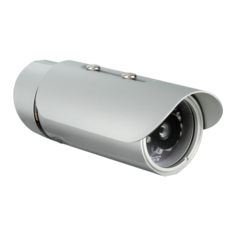
Vigilance Outdoor Bullet Camera
DCS-4714E
DCS-4718E
Contents
ENGLISH 1
DEUTSCH 7
FRANÇAIS 13
ESPAÑOL 19
ITALIANO 25
РУССКИЙ 31
УКРАЇНСЬКА 40
Quick Installation Guide 1
ENGLISH
Hardware Overview
DCS-4712E/DCS-4714E Front
Figure 1: DCS-4712E/DCS-4714E
Front View Features
# Feature Description
1 Camera Lens Fixed camera lens.
2 Light Sensor
The IR-Cut removable sensor
monitors lighting conditions
and switches between color and
infrared accordingly.
3Adjustable
Mount
Loosen the screw with the
included Allen key to adjust the
camera angle. Tighten it to lock
the camera angle.
Table 1: DCS-4712E/DCS-4714E
Front View Descriptions
DCS-4718E Front
Figure 2: DCS-4718E Front View Features
# Feature Description
1 Camera Lens Motorized vari-focal lens.
2 Light Sensor
The IR-Cut removable sensor
monitors lighting conditions
and switches between color and
infrared accordingly.
3Adjustable
Mount
Loosen the screw with the
included Allen key to adjust the
camera angle. Tighten it to lock
the camera angle.
Table 2: DCS-4718E Front View Descriptions
Before You Begin
This installation guide provids instructions
for installing and configuring your camera.
Additional documentation is also available on
the D-Link support website.
Refer to the manual for your model for
additional information on how to configure
the device using the associated Setup Wizard.
The manual and Setup Wizard may be found at
https://dlink.com/support/.
Package Contents
This package includes the following items:
• Vigilance Outdoor Bullet Camera
• Cable Waterproofing Connector
• Mounting Kit
• Allen Key
• Alignment Sticker
• Documentation
If any of the above items are damaged or
missing, please contact your local D-Link reseller.
Note: Using a power supply with a different
voltage than the one recommended for the
device will cause damage and void the warranty
for this product.
System Requirements
• Computer running Microsoft Windows®
• Internet Explorer 11
1
2
3
1
2
3
2Quick Installation Guide
ENGLISH
Cable Interfaces
Figure 3: Cable Interfaces
# Feature Description
1Ethernet
Jack
RJ-45 connector for Ethernet. Can
also be used to power the camera
using Power over Ethernet (PoE)
2Power
Connector
Connects to an optional 12 V / 1.5 A
power adapter (not included)
3Reset
Button
Press and hold for more than five
seconds, then release to perform
a factory reset.
Table 3: Cable Interface Descriptions
DCS-4712E/DCS-4714E Rear Panel
Interfaces
Figure 4: DCS-4712E/DCS-4714E
Rear Panel Interfaces
# Feature Description
1 microSD Slot Slot for a microSD card.
Table 4: DCS-4712E/DCS-4714E Rear
Panel Interface Descriptions
DCS-4718E Bottom Panel Interfaces
Figure 5: DCS-4718E Bottom Panel Interfaces
# Feature Description
1microSD
Slot
Slot for a microSD card.
Table 5: DCS-4718E Bottom Panel
Interface Descriptions
Management Options
To configure and manage your camera, it
is recommended that you download the
associated Setup Wizard and the D-ViewCam
software suite, both of which are available from
the D-Link website.
Installing the Setup Wizard
1. Open a web browser, navigate to
dlink.com/support/, and select your
region.
2. On the next screen, enter the model
number of your camera in the search bar
and click Search. Click the picture of your
camera. On the product page, click the
Download button next to SetupWizard.
3. Once the executable file has finished
downloading, click it and follow the
instructions to install the Setup Wizard.
1
1
1
2
3
Quick Installation Guide 3
ENGLISH
Conguring the Camera
1. Ensure that your camera is plugged in
(either using a 12 V 1.5 A power adapter
or a PoE-enabled device) and connected
to your computer with an Ethernet cable.
2. Open the Setup Wizard. It will display
the MAC address and IP address of your
camera. If you have a DHCP server on your
network, this will be a dynamic IP address. If
your network does not use a DHCP server,
the network camera’s default IP address
192.168.0.20 will be displayed. Select
your camera, then click the Link button to
continue.
Figure 6: Launching the Setup Wizard
3. If this is your first time logging in, you will
be prompted to create a password, which
must be between 8 and 30 characters and
must contain both letters and numbers.
Press Save.
Figure 7: Creating a Password
4. To view the camera display, click the Search
button on the main screen of the Setup
Wizard, then select your camera and click the
Link button to open the camera’s web UI.
Alternatively, open a web browser and type the
camera’s IP address (displayed in step 2) into the
address bar and press Enter. Enter the newly
created password, and click Login to continue.
Figure 8: Authentication
Installing D-ViewCam
1. Open a web browser, navigate to
dlink.com/support/, and select your
region.
2. On the next screen, click the D-ViewCam
link and click the most recent version to
download the D-ViewCam setup wizard
(packaged as a zip file).
3. Once the file has finished downloading,
unzip it, and click the executable file
SetupTool.exe. Follow the instructions
to install the D-ViewCam software suite.
For advanced viewing options, refer to the
D-ViewCam User Manual.
4Quick Installation Guide
ENGLISH
Mounting the Camera
Note: It is highly recommended that you
configure and test your camera before mounting
it. If you plan on inserting a microSD card, it is
also recommended to do this before mounting.
1. Place the alignment sticker where you
want to position the camera. Make sure
the camera base will be positioned so
that the cable channel is on the bottom.
2. Use a 4 mm drill bit to make the required
holes approximately 30 mm deep, then
insert the wall anchors into the holes.
Figure 9: Attaching theWall Anchors
3. If you are running the camera cables
through the wall, drill a hole in the center
and pull the cables through the hole. If you
are running the camera cables out the side
of the camera, guide the camera cables
through the cable channel on the base.
Figure 10: Securing the Cables
4. Use the screws provided to mount the
camera to the wall.
Figure 11: Securing the Camera
5. Connect the power and Ethernet cables,
or just the Ethernet cable if you are using
a PoE connection.
Figure 12: Connecting the Cables
6. To adjust the camera’s monitoring
direction, use the Allen key to turn the
adjustment screw counterclockwise to
loosen it, then move the camera to the
desired position and angle. When you
are finished, turn the adjustment screw
clockwise to tighten it.
Quick Installation Guide 5
ENGLISH
Waterproong Your Installation
A round Ethernet cable, a crimping tool, and RJ-45
plugs are required for this procedure.
1. Place the washer around the base of the
Ethernet connector as shown.
Figure 13: Attaching theWasher Ring
2. Thread the bare Ethernet cable through
the waterproof connector as shown.
Figure 14: Threading the Cable
3. Attach an RJ-45 plug to the end of the
cable using a crimping tool.
Figure 15: Attaching the RJ-45 Connector
4. Connect the RJ-45 plug into the Ethernet
connector, then screw the waterproof
connector to the Ethernet connector by
turning it clockwise about one half-turn.
Figure 16: Attaching theWaterproof Connector
5. Screw the back part of the waterproof
connector clockwise until there is a tight
seal around the Ethernet cable.
Figure 17: Tightening the Connector
6. The power connector and reset
button cables are not waterproof. It is
recommended to use waterproof tape
to protect them. Wind the tape around
each cable in an overlapping manner to
cover them.
Figure 18: Wrapping the Power
Connector and Reset Button
6Quick Installation Guide
ENGLISH
Using the DCS-37-4 Mount (optional)
1.
3.
2.
PM4*10mm
Quick Installation Guide 7
ENGLISH
Using the DCS-37-6 Mount (optional)
1.
3.
2.
TECHNICAL SUPPORT dlink.com/support
8Quick Installation Guide
ENGLISH
Additional Information
If you are encountering problems setting up
your network, please refer to the user manual.
Additional help is available online. To find out
more about D-Link products or marketing
information, please visit the D-Link support
website at http://dlink.com/support/.
Warranty Information
Please visit http://warranty.dlink.com/ for
warranty information for your region.
Model no.
DCS-37-4 DCS-37-6
Screw hole Screw size Screw hole Screw size
DCS-4712EK
DCS-4717EK A PM4*10mm D PM4*10mm
DCS-4718EK B PM4*10mm C PM4*10mm
Installation Information
Quick Installation Guide 9
DEUTSCH
Hardware-Übersicht
DCS-4712E/DCS-4714E Vorderseite
Abbildung 1: DCS-4712E/DCS-4714E
Elemente Vorderseite
Nr. Funktion Beschreibung
1 Kameraobjektiv Festes Kameraobjektiv.
2 Lichtsensor
Der austauschbare IR-Cut Sensor
prüft die Lichtverhältnisse
und wechselt entsprechend
zwischen Farbe und Infrarot.
3Anpassbare
Halterung
Lockern Siedie Schraubemit dem
Innensechskantschlüssel, um
den Kamerawinkel anzupassen.
Ziehen Sie die Schraube fest, um
den Kamerawinkel zu fixieren.
Tabelle 1: DCS-4712E/DCS-4714E
Beschreibung Vorderseite
DCS-4718E Front
Figure 2: DCS-4718E Front View Features
Nr. Funktion Beschreibung
1 Kameraobjektiv Motorisiertes Zoomobjektiv.
2 Lichtsensor
Der austauschbare IR-Cut Sensor
prüft die Lichtverhältnisse
und wechselt entsprechend
zwischen Farbe und Infrarot.
3Anpassbare
Halterung
Lockern Siedie Schraubemit dem
Innensechskantschlüssel, um
den Kamerawinkel anzupassen.
Ziehen Sie die Schraube fest, um
den Kamerawinkel zu fixieren.
Tabelle 2: DCS-4712E/DCS-4714E
Beschreibung Vorderseite
Vor der Inbetriebnahme
Diese Installationsanleitung beschreibt die
Installation und Konfiguration Ihrer Kamera.
Weitere Unterlagen finden Sie auf der Support-
Website von D-Link.
Für weitere Informationen zur Konfiguration
des Geräts mit dem Setup-Assistenten siehe
das Handbuch Ihres Produkts. Handbuch
und Setup-Assistenten finden Sie unter
https://dlink.com/support/.
Packungsinhalt
Im Lieferumfang ist Folgendes enthalten:
• Vigilance Outdoor Bullet Camera
• Wasserdichter Steckverbinder
• Montageset
• Innensechskantschlüssel
• Klebeschablone
• Dokumentation
Sollte eines der oben aufgeführten Teile
beschädigt sein oder fehlen, wenden Sie sich
bitte an Ihren D-Link-Händler vor Ort.
Hinweis: Die Verwendung eines Netzteils mit
einer anderen Betriebsspannung als der für
dieses Gerät empfohlenen führt zu Schäden
und einem Erlöschen des Garantieanspruchs
für dieses Produkt.
Systemvoraussetzungen
• Computer mit Microsoft Windows®
• Internet Explorer 11
1
2
3
1
2
3
10 Quick Installation Guide
DEUTSCH
Kabel
Abbildung 3: Kabel
Nr. Funktion Beschreibung
1Ethernet-
Anschluss
RJ-45-Verbindungsstecker
für Ethernet. Kann auch für
die Stromzufuhr mittels PoE
für die Kamera verwendet
werden
2 Stromanschluss
Zum Anschluss an ein
Netzteil (12 V / 1,5 A) (nicht
im Lieferumfang enthalten)
3 Reset-Taste
Halten Sie die Taste über fünf
Sekunden lang gedrückt und
lassen Sie dann los, um das
Gerät auf Werkseinstellungen
zurückzusetzen.
Tabelle 3: Beschreibung Kabel
DCS-4712E/DCS-4714E Anschlüsse
Rückseite
Abbildung 4: DCS-4712E/DCS-4714E
Anschlüsse Rückseite
Nr. Funktion Beschreibung
1microSD-
Steckplatz
Steckplatz für microSD-Karte.
Tabelle 4: DCS-4712E/DCS-4714E
Beschreibung Anschlüsse Rückseite
DCS-4718E Anschlüsse Unterseite
Abbildung 5: DCS-4718E Anschlüsse Unterseite
Nr. Funktion Beschreibung
1microSD-
Steckplatz
Steckplatz für microSD-Karte.
Tabelle 5: /DCS-4718E Beschreibung
Anschlüsse Unterseite
Kameraverwaltung
Es wird empfohlen, für Konfiguration und
Verwaltung Ihrer Kamera den entsprechenden
Setup-Assistenten und die D-ViewCam-Software
von der D-Link-Website herunterzuladen.
Den Setup-Assistenten installieren
1. Öffnen Sie dlink.com/support/ in einem
Webbrowser und wählen Sie Ihre Region.
2. Geben Sie im nächsten Bildschirm die
Modellnummer Ihrer Kamera in die
Suchleiste ein und klicken Sie auf Suchen.
Klicken Sie auf das Bild Ihrer Kamera.
Klicken Sie auf der Produktseite neben
Setup-Assistent auf Download.
3. Klicken Sie auf die heruntergeladene
ausführbare Datei und folgen Sie den
Anweisungen, um den Setup-Assistenten
zu installieren.
1
1
1
2
3
Quick Installation Guide 11
DEUTSCH
Die Kamera kongurieren
1. Stellen Sie sicher, dass die Kamera mit
Strom versorgt wird (entweder über ein
Netzteil mit 12 V/1,5 A oder ein PoE-
Gerät) und per Ethernet-Kabel mit Ihrem
Computer verbunden ist.
2. Öffnen Sie den Setup-Assistenten. Er zeigt
die MAC- und IP-Adresse Ihrer Kamera an.
Wenn in Ihrem Netzwerk ein DHCP-Server
vorhanden ist, ist dies eine dynamische
IP-Adresse. Wenn Ihr Netzwerk keinen
DHCP-Server verwendet, wird die
Standard-IP-Adresse der Netzwerkkamera
angezeigt (192.168.0.20). Wählen Sie Ihre
Kamera aus und klicken Sie auf Link, um
fortzufahren.
Abbildung 6: Den Setup-Assistenten starten
3. Wenn Sie sich zum ersten Mal anmelden,
werden Sie aufgefordert, ein Kennwort
zu erstellen. Es muss zwischen 8 und 30
Zeichen lang sein und Buchstaben und
Ziffern enthalten. Klicken Sie auf Save
(Speichern).
Abbildung 7: Ein Kennwort erstellen
4. Um die Kamera anzuzeigen, klicken Sie im
Hauptbildschirm des Setup-Assistenten auf
Search (Suche), wählen Sie Ihre Kamera
aus und klicken Sie auf Link, um die Web-
Benutzeroberfläche der Kamera zu öffnen.
Alternativ können Sie auch die in Schritt 2
angezeigte IP-Adresse der Kamera in die
Adresszeile eines Webbrowsers eingeben und
die Eingabetaste drücken. Geben Sie das neu
erstellte Kennwort ein und klicken Sie auf Login
(Anmelden).
Abbildung 8: Authentizierung
D-ViewCam installieren
1. Öffnen Sie dlink.com/support/ in einem
Webbrowser und wählen Sie Ihre Region.
2. Klicken Sie im nächsten Bildschirm auf
den D-ViewCam-Link und auf die aktuelle
Version, um den D-ViewCam Setup-
Assistenten als Zip-Datei herunterzuladen.
3. Entpacken Sie die heruntergeladene
Datei und klicken Sie auf die ausführbare
Datei SetupTool.exe. Folgen Sie den
Anweisungen zur Installation der
D-ViewCam Software.
Für weitere Ansichtsoptionen siehe das
D-ViewCam-Benutzerhandbuch.
Montage der Kamera
Hinweis: Es ist unbedingt ratsam, die Kamera
zuerst zu konfigurieren und zu testen, bevor
Sie sie montieren.Wenn Sie eine microSD-Karte
einsetzen möchten, sollten Sie dies ebenfalls vor
12 Quick Installation Guide
DEUTSCH
der Montage tun.
1. Platzieren Sie die Klebeschablone für die
Montage dort, wo die Kamera positioniert
werden soll. Stellen Sie sicher, dass der
Kamerasockel so ausgerichtet ist, dass der
Kabelkanal unten ist.
2. Bohren Sie mit einem 4-mm-Bohreinsatz
etwa 30 mm tiefe Löcher. Stecken Sie dann
die Dübel in die Löcher.
Abbildung 9: Dübel für die
Wandhalterung montieren
3. Sollen die Kamerakabel durch die Wand
geführt werden, bohren Sie ein Loch in die
Mitte und führen Sie die Kabel hindurch.
Wenn die Führung der Kamerakabel
außerhalb der Kamera erfolgen soll, führen
Sie die Kamerakabel durch den Kabelkanal
des Sockels.
Abbildung 10: Kabel anbringen
4. Befestigen Sie die Kamera mit den
mitgelieferten Schrauben an der Wand.
Abbildung 11: Montage der Kamera
5. Schließen Sie Strom- und Ethernet-Kabel
an (oder nur das Ethernet-Kabel, wenn Sie
eine PoE-Verbindung nutzen).
Abbildung 12: Kabel anschließen
6. Um den Winkel der Kamera einzustellen,
lockern Sie die Einstellschraube, indem
Sie sie mit dem Innensechskantschlüssel
gegen den Uhrzeigersinn drehen. Stellen
Sie dann die Kamera auf die gewünschte
Position und den gewünschtenWinkel ein.
Ist die gewünschte Position eingestellt,
drehen Sie die Einstellschraube im
Uhrzeigersinn, um die Position zu fixieren.
Quick Installation Guide 13
DEUTSCH
DieInstallation wasserdicht machen
Dafür benötigen Sie ein rundes Ethernet-Kabel,
eine Crimpzange und RJ-45 Stecker.
1. Bringen Sie den Dichtungsring wie
abgebildet auf dem Ethernet-
Steckverbinder an.
Abbildung 13: Unterlegscheibe anbringen
2. Führen Sie das blanke Ethernet-Kabel
wie abgebildet durch den wasserdichten
Steckverbinder.
Abbildung 14: Kabel durchführen
3. Bringen Sie mit der Crimpzange einen
RJ-45-Stecker am Kabelende an.
Abbildung 15: RJ-45-Stecker anbringen
4. Stecken Sie den RJ-45 Stecker in den
Ethernet-Steckverbinder und drehen Sie
den wasserdichten Steckverbinder im
Uhrzeigersinn etwa eine halbeUmdrehung
auf den Ethernet-Steckverbinder.
Abbildung 16: Wasserdichten
Steckerbinder anbringen
5. Drehen Sie den hinteren Teil des
wasserdichten Steckverbinders im
Uhrzeigersinn, bis eine feste Abdichtung
um das Ethernet-Kabel erreicht ist.
Abbildung 17: Steckverbinder xieren
6. Netzanschluss- und Reset-Kabel sind
nicht wasserdicht. Es wird empfohlen,
sie mit wasserdichtem Klebeband zu
schützen. Umwickeln Sie dazu die Kabel
überlappend mit Klebeband.
Abbildung 18: Netzanschluss und
Reset-Taste umwickeln
14 Quick Installation Guide
DEUTSCH
Verwendung der DCS-37-4-Halterung (optional)
1.
3.
2.
PM4*10mm
Quick Installation Guide 15
DEUTSCH
Verwendung der DCS-37-6-Halterung (optional)
1.
3.
2.
16 Quick Installation Guide
DEUTSCH
Modellnr.
DCS-37-4 DCS-37-6
Loch für Schraube Schraubengröße Loch für Schraube Schraubengröße
DCS-4712EK
DCS-4717EK A PM4*10mm D PM4*10mm
DCS-4718EK B PM4*10mm C PM4*10mm
Montageinformationen
Weitere Informationen
Wenn Sie Probleme bei der Einrichtung
Ihres Netzwerks haben, lesen Sie bitte das
Benutzerhandbuch.
Weitere Hilfe erhalten Sie online. Um mehr
über D-Link-Produkte zu erfahren oder
Marketinginformationen zu erhalten, besuchen
Sie die D-Link Support-Website unter http://
dlink.com/support/.
Garantieinformationen
Landesspezifische Informationen zur
Gewährleistung finden Sie unter
http://warranty.dlink.com/.
TECHNISCHE UNTERSTÜTZUNG eu.dlink.com/support
Quick Installation Guide 17
FRANÇAIS
Vue d'ensemble du matériel
DCS-4712E/DCS-4714E Avant
Figure 1: DCS-4712E/DCS-4714E
Caractéristiques de la vue avant
N° Caractéristique Description
1Objectif de
la caméra
Objectif fixe de la caméra.
2Capteur de
lumière
Le capteur PIR surveille les
conditions d'éclairage et alterne
entre la couleur et l'infrarouge en
conséquence.
3Monture
ajustable
Desserrez la vis à l’aide de la clé
Allen fournie pour régler l'angle de
la caméra. Serrez-la pour bloquer
l'angle de la caméra.
Tableau 1: DCS-4712E/DCS-4714E
Descriptions de la vue avant
DCS-4718E Avant
Figure 2: DCS-4718E Caractéristiques
de la vue avant
N° Caractéristique Description
1Objectif de
la caméra
Lentille vari-focale motorisée.
2Capteur de
lumière
Le capteur PIR surveille les
conditions d'éclairage et alterne
entre la couleur et l'infrarouge en
conséquence.
3Monture
ajustable
Desserrez la vis à l’aide de la clé
Allen fourniepour régler l'anglede
la caméra. Serrez-la pour bloquer
l'angle de la caméra.
Tableau 2: DCS-4718E Descriptions
de la vue avant
Avant de commencer
Ce guide d'installation fournit des instructions
pour l'installation et la configuration de votre
caméra. Une documentation supplémentaire
est également disponible sur le site Web
d'assistance D-Link.
Reportez-vous au manuel de votre modèle pour
obtenir des informations supplémentaires sur la
manière de configurer le périphérique à l'aide de
l'assistant de configuration associé. Le manuel
et l'assistant de configuration se trouvent à
l'adresse suivante https://dlink.com/support/.
Contenu de la boîte
Ce paquet comprend les éléments suivants :
• Vigilance Outdoor Bullet Camera
• Connecteur pour l'étanchéité des câbles
• Kit de montage
• Clé Allen
• Autocollant d'alignement
• Documentation
Si l'un des éléments ci-dessus est endommagé
ou manquant, contactez votre revendeur local
D-Link.
Remarque: L'utilisation d'une alimentation
électrique dont la tension est différente de celle
recommandée pour le périphérique provoquera
des dommages et annulera la garantie de ce
produit.
Conguration système requise
• Ordinateur fonctionnant sous Microsoft
Windows®.
• Internet Explorer 11
1
2
3
1
2
3
18 Quick Installation Guide
FRANÇAIS
Interfaces des câbles
Figure 3: Interfaces des câbles
N° Caractéristique Description
1Connecteur
Ethernet
Connecteur RJ-45 pour
Ethernet. Peut également
être utilisé pour alimenter
la caméra en utilisant
l'alimentation par Ethernet
(PoE)
2Connecteur
d’alimentation
Se connecte à un adaptateur
d’alimentation de 12 V / 1,5 A
optionnel (non inclus)
3Bouton de
réinitialisation
Maintenez la touche
enfoncée pendant plus
de cinq secondes, puis
relâchez-la pour effectuer
une réinitialisation.
Tableau 3: Descriptions des interfaces de câbles
DCS-4712E/DCS-4714E Interfaces
de la face arrière
Figure 4: DCS-4712E/DCS-4714E
Interfaces de la face arrière
N° Caractéristique Description
1Port de carte
microSD
Emplacement pour une carte
microSD.
Tableau 4: DCS-4712E/DCS-4714E Descriptions
des interfaces du panneau arrière
DCS-4718E Interfaces du panneau
inférieur
Figure 5: DCS-4718E Interfaces
du panneau inférieur
N° Caractéristique Description
1Port de carte
microSD
Emplacement pour une carte
microSD.
Tableau 5: DCS-4718E Descriptions des
interfaces du panneau inférieur
Options de gestion
Pour configurer et gérer votre caméra, il est
recommandé de télécharger l'assistant de
configuration associé et la suite logicielle
D-ViewCam, qui sont tous deux disponibles sur
le site web de D-Link.
Installation de l'assistant de
conguration
1. Ouvrez un navigateur Web, accédez à
dlink.com/support/, et sélectionnez
votre région.
2. Sur l'écran suivant, saisissez le numéro de
modèle de votre caméra dans la barre de
recherche et cliquez Rechercher. Cliquez
sur l'image de votre caméra. Sur la page du
produit, cliquez sur le bouton Télécharger
à côté de l'assistant d'installation.
3. Une fois le téléchargement du fichier
exécutable terminé, cliquez dessus et
suivez les instructions pour installer
l'assistant d'installation.
1
1
1
2
3

Other manuals for DCS-4712E

1

This manual suits for next models

2

Other D-Link Security Camera manuals

D-Link DCS-3410 User manual

D-Link

D-Link DCS-3410 User manual

D-Link Securicam DCS-3415 User manual

D-Link

D-Link Securicam DCS-3415 User manual

D-Link DCS-H100 User manual

D-Link

D-Link DCS-H100 User manual

D-Link DCS-3112 User manual

D-Link

D-Link DCS-3112 User manual

D-Link DCS-942L User manual

D-Link

D-Link DCS-942L User manual

D-Link BEYOND FIBER MSME SECURITY KIT User manual

D-Link

D-Link BEYOND FIBER MSME SECURITY KIT User manual

D-Link DCS-6314 User manual

D-Link

D-Link DCS-6314 User manual

D-Link DCS-8325LH User manual

D-Link

D-Link DCS-8325LH User manual

D-Link DCS-5222L User manual

D-Link

D-Link DCS-5222L User manual

D-Link SECURICAM DCS-5605 User manual

D-Link

D-Link SECURICAM DCS-5605 User manual

D-Link DCS-935L User manual

D-Link

D-Link DCS-935L User manual

D-Link DCS-942L User manual

D-Link

D-Link DCS-942L User manual

D-Link DCS-5000L User manual

D-Link

D-Link DCS-5000L User manual

D-Link DCS-71 Series User manual

D-Link

D-Link DCS-71 Series User manual

D-Link SECURICAM DCS-5605 User manual

D-Link

D-Link SECURICAM DCS-5605 User manual

D-Link Vigilance H.265 User manual

D-Link

D-Link Vigilance H.265 User manual

D-Link DCS-932L User manual

D-Link

D-Link DCS-932L User manual

D-Link DCS-3410 User manual

D-Link

D-Link DCS-3410 User manual

D-Link DCS-5230 User manual

D-Link

D-Link DCS-5230 User manual

D-Link DCS-2136L User manual

D-Link

D-Link DCS-2136L User manual

D-Link DCS-936L User manual

D-Link

D-Link DCS-936L User manual

D-Link DCS-934L User manual

D-Link

D-Link DCS-934L User manual

D-Link DCS-4705E User manual

D-Link

D-Link DCS-4705E User manual

D-Link SECURICAM DCS-7110 User manual

D-Link

D-Link SECURICAM DCS-7110 User manual

Popular Security Camera manuals by other brands

Samsung SCV-2010F user manual

Samsung

Samsung SCV-2010F user manual

Videology 20/21Z704 Communications manual

Videology

Videology 20/21Z704 Communications manual

Optus SecureCam user guide

Optus

Optus SecureCam user guide

Axis P3905-RE user manual

Axis

Axis P3905-RE user manual

urmet domus 1092/601 THERA 4 MINIDOME P/T/Z instruction manual

urmet domus

urmet domus 1092/601 THERA 4 MINIDOME P/T/Z instruction manual

Mace MaceView Covert Series user guide

Mace

Mace MaceView Covert Series user guide

DeView MD3CN12M Quick installation guide

DeView

DeView MD3CN12M Quick installation guide

Wansview W3 user manual

Wansview

Wansview W3 user manual

LevelOne FCS-5044 user manual

LevelOne

LevelOne FCS-5044 user manual

Vitek VTD-VPH266 Specifications

Vitek

Vitek VTD-VPH266 Specifications

Santec VCHD-1622 user manual

Santec

Santec VCHD-1622 user manual

Panasonic WV-CF400 operating instructions

Panasonic

Panasonic WV-CF400 operating instructions

Novus NVIP-1DN5001H/IRH-1P user manual

Novus

Novus NVIP-1DN5001H/IRH-1P user manual

Mami VeriCAM 4 Operation manual

Mami

Mami VeriCAM 4 Operation manual

Surveon CAM2441HI user manual

Surveon

Surveon CAM2441HI user manual

Dedicated Micros 2060 Operation manual

Dedicated Micros

Dedicated Micros 2060 Operation manual

Eneo NXD-1602M user manual

Eneo

Eneo NXD-1602M user manual

Monacor AVC-400 quick guide

Monacor

Monacor AVC-400 quick guide

manuals.online logo
manuals.online logoBrands
  • About & Mission
  • Contact us
  • Privacy Policy
  • Terms and Conditions

Copyright 2025 Manuals.Online. All Rights Reserved.