DAITEM SH148AX User manual


GB
16
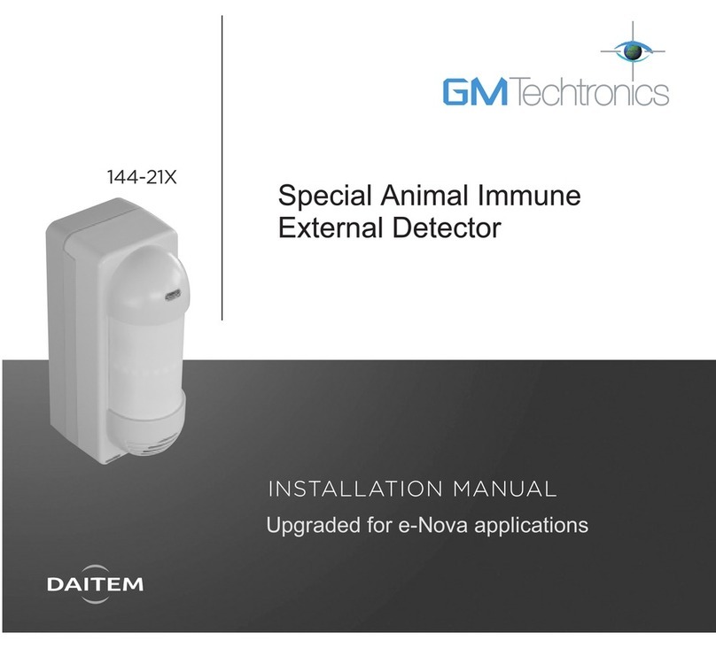
The outdoor anti-masking detector has been specially designed to
detect intruders before they break in and is able to tell the difference
between a human being and an animal.
Its anti-masking function allows it to detect attempts to mask
detection.
The detector has 2 detection beams (upper and lower), both of which
must be broken simultaneously for the alarm to be triggered. The
detection process prevents the device from triggering false alarms
due to the sun or the headlights of a car.
urthermore, a temperature compensation system automatically
increases and backs up detection sensitivity.
Its compact size, narrow horizontal protection, smaller detection
range and anti-masking function make it an ideal device for
protecting façades, balconies, various types of windows and any
other access points.
Contents
1. Introduction ........................................................................................... 16
2. Preparation ............................................................................................ 17
2.1 Opening the detector........................................................................ 17
2.2 Description ........................................................................................ 17
2.3 Power supply .................................................................................... 18
3. Recognition programming................................................................... 19
4. Parameter-setting................................................................................. 20
5. Installation precautions........................................................................ 21
6. Installing the detector .......................................................................... 22
6.1 Testing the radio link......................................................................... 22
6.2 ixing the detector in place .............................................................. 22
7. Detection settings and configuration................................................. 23
7.1 Detection range................................................................................. 23
7.2 Adjusting the detection angle horizontally ....................................... 25
7.3 Setting the operating options ........................................................... 25
7.4 Anti-masking function....................................................................... 26
8. Testing operation .................................................................................. 27
8.1 Testing the detection zone................................................................ 27
8.2 Performing a real test........................................................................ 27
9. Maintenance.......................................................................................... 28
9.1 ault indications................................................................................ 28
9.2 Changing the batter.......................................................................... 28
10. Technical data ..................................................................................... 29
1. Introduction
Recommendations
The user must not attempt to access the detector’s internal parts, except areas described in this manual. If the user does access these parts,
the product guarantee will be considered null and void and DAITEM shall not be held responsible for any problems. Touching the detector’s
internal parts and/or electronic components can damage the product. urthermore, the detector is designed in such a way that these parts
and components do not need to be accessed for operation or maintenance purposes.
IMPORTANT
• Some functions are only available with control panel version 2.0.0 or
later (enter ) on the control panel keypad
to check the version).
• Operating differences with respect to former ranges are described in
the compatibility booklet available in the Daitem Installers section at
www.daitem.co.uk.
GB
17
Remove the base.
2. Preparation
2.1 Opening the detector 2.2 Description
N.B. The product is delivered unscrewed.
d
ixing
at 2 points
(screws not
supplied)
Ba e
Radio box
Radio card
Guarantee sticker
Test button
Programming LED
Lithium battery
Tamper tab
Detection module
Upper detection
beam
Lower detection
beam LED indicator
Tamper tab
Locking mechanism
Dip switches
for operating
options
SH148AX
A1142A047879
Collersur certif
SH148AX
A1142A047879
Collersur certif
1 screw to be positioned on
the snap-off part to ensure
protection against removal
(screw not supplied).

GB
18
IMPORTANT: when powered, the LED
indicator positioned behind the lower
lens flashes quickly for several
seconds before going out (detection
circuit stabilisation period).
1. Connect the lithium power pack referring
to the arrow to make sure it is the right way
round.
When powered, the detector performs
a self-test.
If the self-test is satisfactory, the programming
indicator lights up for roughly 2 s.
2. Guarantee sticker
Remove the pre-cut part of the sticker and stick it to the guarantee certificate in the
user manual supplied with the control panel. If you are adding to an existing system,
use the guarantee certificate supplied with this product.
2.3 Power supply
In ide view of radio box Front panel
LED indicator
Unlocking tab
Programming LED
Guarantee
sticker
Upper lens
Lower lens
Front panel
(head-on view)
Front panel
(in ide view)
Closing
screw
Sticker listing
operating
options
Directional arrow
SH148AX
A1142A047879
Coller sur certif
SH148AX
A1142A047879
Coller sur certif

GB
19
3. Recognition programming
IMPORTANT
• The device does not need to be placed close to the control panel for recognition programming. In fact, we advise you to move the
product at least 2 metres away from the control panel.
• The detector n° is allocated automatically by the control panel during recognition programming.
This operation allows the control panel to recognise the detector.
2. Proceed as follows for recognition programming:
1. or detector recognition programming, the control panel must be in installation mode. If it is not, ask the user to enter:
then
IMPORTANT: the control panel issues three short beeps to indicate a programming error. When this happens, programming must
be performed again from the beginning.
Press *then #on
the control panel
keypad.
Press and hold the “test”
button until the control
panel responds.
Select the group from 1 to
8*. Use the control panel
keypad to do this.
Select the time delay:
0: immediate
1: delayed
2: combined
Use the control panel
keypad to do this.
The control panel
issues a voice
message to confirm
detector recognition
programming.
then to
)))))
10 s max.
“detector X” “group ?” “time delay?”
*to
* depending on the
type of control panel
master code (factory: 0000) installer code (factory: 1111)
“beep, detector X,
group Y, immediate
(or delayed
or combined)”
“beep, installation
mode”

GB
20
The motion detector is factory-configured
for deterrence (see your control panel
installation guide for system responses).
The alarm level can be changed by resetting
the parameters as shown opposite.
Parameter-setting sequence
Programming
LED off
Programming
LED on
Programming
sequence
about
5 s. about 10 s. about 2 s.
about 10 s.
To start,
press and
hold until the
LED goes out.
Press the button
5 times for the
parameter
number
Press and
hold until the
LED briefly
goes out
Press the button
1 to 4 times for the
parameter value
To end, press
and hold the
button until the
LED goes out
Programming
LED steadily lit
= parameter
set correctly
Start Press the
button 5 times
to select the
alarm level
Press
once to
create a
space
Press the button
twice to select the
prealarm level.
End
Parameter-setting example: setting the
detector to prealarm level: parameter
number 5, parameter value 2. 5 2 about 2 s.
tt
4. Parameter-setting
{
{
Parameter N° Alarm level Parameter value
5
Intrusion 1
Prealarm 2
Deterrence 3 (factory setting)
Warning 4 (function compatible with control panel
versions 2.0.0 and later)

GB
21
The detector must be placed:
• at a height of 0.8 to 1.2 m,
• facing a moving object (branches, bushes,
curtains, etc.),
• directly on a metal wall or close to sources
of interference (e.g. electricity meter) or
ventilation (air conditioning, heat pump,
etc.).
5. Installation precautions
IMPORTANT: make sure each product is at least two metres away from other devices, except other detectors.
The detector must not be placed:
• in a location where the detection beams
are likely to be directly or indirectly
impacted by the sun’s rays or by a very
powerful source of light,
H
• perpendicular to entrance points to be
protected to ensure intruders are quickly
detected,
Right
Wrong
• perpendicular to the
ground so that the
upper detection
zone is parallel to
the ground. If the
detector is at a
slope in relation to
the ground, its
operation may not
be as reliable.

GB
22
1. Before fixing the detectors in place,
position them in the location where they
are to be installed and check the radio
links with the control panel. If the link with
the control panel is satisfactory, the
control panel issues a voice message
identifying the device activated.
2. Press (> 5 s) on the “test” button of each
detector. The control panel will issue the
voice message: “beep, test detector X,
group Y, (immediate or delayed or
combined)”.
)))))
“beep, test detector X, group Y,
(immediate or delayed
or combined)”
d
1. ix the base to the wall using suitable
wall plugs and screws (i.e. with a
maximum diameter of 3 mm,
not supplied)
2. Position the 2 screw covers on the
fixing screws to ensure product water
tightness.
3. Position the radio box on the base.
6. Installing the detector
6.1 Testing the radio link 6.2 ixing the detector in place
4. Then tighten the screw.
.
IMPORTANT: the control panel must be in
installation mode to perform this test.
Screw covers
ixing screws
(max screw Ø ⭐3 mm)
A screw
(max Ø ⭐3 mm)
must be used to protect
the device from being
removed

GB
23
The detector’s overall range is determined by
the lower beam range.
• The upper beam must always be parallel
to the ground
• The lower beam must be adjusted in
relation to the position of the lower lens (2
m or 5 m mark).
• Given that the 2 beams must be
simultaneously broken to trigger an alarm,
the detector range is limited to the lower
beam range as shown in the diagram
below.
7. Detection settings and configuration
7.1 Detection range
IMPORTANT
• The 2 m or 5 m indications on the product
should only be used to help position the
lower lens.
• To determine the detection range, please
refer to the tables above.
d
1. Unscrew and open the front panel.
2.
Unclip the lower lens and rotate it 180°
before repositioning it.
.
Inside front panel
Lower
lens
Upper lens
Detection table for lower lens set
at 5 m
• The lower lens is factory-positioned for
detection at 5 m. If 2 m detection is
required:
• The detection range is determined by the
lower lens setting and the detector
installation height.
* Detection range data may vary in relation to atmospheric
conditions.
Installation
height (m) 0.8 0.9 1 1.1 1.2
Detection range
(m)* 6 7 7.5 8 8.5
Detection table for lower lens
set at 2 m
* Detection range data may vary in relation to atmospheric
conditions.
Installation
height (m) 0.8 0.9 1 1.1 1.2
Detection range
(m)* 3 3.5 3.7 4 4.2
A. no detection: only the lower beam is broken.
B. detection: the lower and upper beams are
broken.
C. no detection: only the upper beam is broken.
C
B
A
IMPORTANT: do not
remove the upper lens

GB
24
To set the detection zone:
1. Remove the locking
mechanism using a
flat-headed
screwdriver. Carefully
insert the screwdriver
into the right-hand
and then left-hand
openings and push
upwards.
2. Hold the detection module and
point it in the required direction
adjusting it 5° at a time.
4. Reposition the locking mechanism to block the
detection module in its final location.
3. or protection along a vertical surface (wall, bay window, etc.), it is advisable
to align the detection zone parallel with this surface:
• for improved detection,
• to reduce interference caused by this surface.
7.2 Adjusting the detection angle horizontally
IMPORTANT: check that the
locking mechanism is properly
inserted in the slots.
Detection zone setting range
Locking
mechanism
Top view
Setting range: 95°
(in 5° adjustments)
Setting range: 95°
(in 5° adjustments)
5° adjustments
The marks on the locking system help to achieve the
optimal adjustment in this configuration. Choose the
mark located on the opposite side of the surface
before repositioning the locking mechanism.

GB
25
Detector in test mode
The LED lights up each time something is detected making it possible to test the range.
Triggering time delay (factory setting)
Set for 120 s, even when something is permanently detected, the radio transmission is only
activated once every 120 s. Position recommended if there is frequent activity inside the
detection zone.
Mandatory position (factory setting)
LED indicator status selection (factory setting)
The LED does not light up with every detection (unless dip switch n°1 is ON).
Position recommended if there is frequent activity inside the detection zone.
Normal detector sensitivity (factory setting)
This setting is suitable for most installations.
Anti-masking function enabled (factory setting)
If the device is masked, the LED indicator flashes 3 times in a row every 5 seconds throughout
the duration of the fault (if dip switch n° 4 is ON).
The options are set using the 6 dip switches inside the detection module.
1 2 3 4 5 6
ON
1 2 3 4 5 6
ON
Detector in normal user mode (factory setting)
The LED remains unlit (unless dip switch n° 4 is ON). The frequency of radio message
transmission depends on the position of dip switch n° 2.
1 2 3 4 5 6
ON
Triggering time delay
Set for 5 s, even when something is permanently detected, the radio transmission is only
activated once every 5 s.
1 2 3 4 5 6
ON
1 2 3 4 5 6
ON
1 2 3 4 5 6
ON
LED indicator status selection
The LED lights up with every detection
1 2 3 4 5 6
ON
1 2 3 4 5 6
ON
1 2 3 4 5 6
ON
Low detector sensitivity
This setting is recommended for difficult environmental conditions (wind, reflecting ground,
high brightness level, etc.)
1 2 3 4 5 6
ON
1 2 3 4 5 6
ON
Anti-masking function disabled
7.3 Setting the operating options
IMPORTANT: if you position dip switch 2 or
dip switch 4 to ON, the battery life will be
shortened.
factory setting
Operating option
dip switches
LED indicator

GB
26
7.4 Anti-masking function
IMPORTANT: during this phase, any object or
person in front of the detector (within a radius
of roughly 1 metre) causes the anti-masking
feature to dysfunction.
The function is operational if:
• the option has been validated (dip switch n°4 ON)
• the product is fixed to the wall and its front panel is closed.
When the above both apply, there are three phases:
1. a recognition programming phase launched for 1 minute so that the detector can adapt the anti-masking function to its close environment,
2. then an intermediary phase lasting roughly ten minutes when front panel masking is detected within 20 s,
3. after this ten-minute period, the normal operating phase begins when front panel masking is detected within 3 minutes.
Product fixed
to the wall
with its front
panel closed
1. programming phase 2. intermediary phase 3. operating phase
1 minute 10 minutes
(detection within 20 s if the front panel is masked)
detection
within 3 minutes
if the front panel
is masked
7.4.1 Masking detected after Arming
When the alarm system is already armed, detector masking triggers a deterrence radio transmission (depending on parameter setting)
roughly 3 minutes after the front panel has been masked.
7.4.2 Masking detected before Arming
When the alarm system is armed and the detector front panel is already masked (for roughly 3 minutes), the alarm control panel issues the
following message to indicate masking:
• “Beep, exit X open” (if the control panel is programmed for “Block arming enabled/parameter 45 set at 1, 2, 3 or 4”). The control panel is
programmed to prevent system arming if a fault is detected or an exit has remained open and it issues the message “Beep, e it X open” to
indicate the fault. In this case, the fault must be cleared to be able to arm the system.
• “Beep, armed, exit X open” (if the control panel is programmed for “Block arming disabled/parameter 45 set at 0”). In this case, the
system is armed even when the detector is masked. The detector concerned is automatically inhibited at the end of the exit time delay
(factory setting: 90 s). The control panel issues the voice message “Beep, armed, exit X inhibited” and the detector is deactivated.
Automatic detector inhibition can be deleted by programming control panel parameter 61 (see control panel installation guide: non-
inhibitable detector). In this case, the detector remains enabled after control panel arming.

GB
27
8. Operating test
8.1 Testing the detection zone
1. Put the control panel in user mode by entering:
2
.
Put the control panel in Total Arm mode.
3. Wait until the end of the exit time delay or 120 s for the detector to become activated.
4. Walk across the protected area and check the control panel response (see control panel installation manual).
8.2 Performing a real test
5. Put the control panel back in installation mode by entering:
6. Open the front panel, switch the dip switch to O and then close the front panel.
1. Switch the dip switch to ON.
2. Close the front panel and tighten the screw.
3. Put the control panel in test mode by entering the following:
4. Check the detection zone using the LED and adjust the detection angle if necessary.
With each detection:
• the LED indicator lights up once for 2 s,
• the control panel issues the voice message, “Beep, deterrence detector X” (the
message depends on the parameter setting), a first time when the detection zone is
entered and a second time when the detection zone is exited.
This real test must be performed at least once a year and notably
before long periods away from home.
installer code
installer code
installer code
Detected
Zone A Zone B
Not detected
Zone A: detection range (determined by the lower
lens position and the installation height).
Perform an operating test to confirm. Detection must
take place in zone A and not in zone B.
IMPORTANT: It is normal for the LED indicator to light up only 2 or 3 seconds later during
the detection zone test.

GB
28
The control panel responds to detector
battery faults, tamper faults, radio faults and
anti-masking faults.
• Battery fault: following a system
command, the control panel issues the
voice message “Beep, fault, battery,
detector X”.
• Tamper fault: following a system
command, the control panel issues the
voice message “Beep, fault, tamper,
detector X”.
This fault is caused by the radio box not
being properly closed on the base or by
the front panel not being properly closed
on the detection module.
• Radio fault: following a system command,
the control panel issues the voice message
“Beep, fault, radio, detector X”.
• Masking fault: when the front panel has
been masked for roughly 3 minutes and
following an arming command, the control
panel issues the voice message “Beep,
e it X open” or “Beep, armed, e it X open”.
9. Maintenance
9.1 ault indications
1. Put the control panel in installation mode by asking the user to enter:
then
2. Open the detector box (see § 2. Opening the detector).
3. Replace the flat lithium battery.
4. Put the control panel back in user mode by entering:
5. Perform a real test (see § 8. Performing a real test).
9.2 Changing the battery
IMPORTANT: the detector’s parameters are saved when the battery is changed.
master code installer code
installer code
• It is essential to replace the lithium battery supplied with the same type of lithium battery offering
the same characteristics (3.6 V - 4 Ah).
• We advise you to use a DAITEM brand BatLi25 battery available in the catalogue in order
to guarantee individual safety and equipment reliability.
• Dispose of the flat lithium battery in the appropriate recycling bin.
Li
N.B.: a deposit of frost on the upper and
lower lens composes an opaque surface
that may have the effect of masking the
front panel.

GB
29
Technical specifications SH148AX
Outdoor IR anti-masking 5 m detector
Type of detection Passive infrared
Coverage can be adjusted to 2 m (12°) or 5 m (12°)
Detection zone setting range 190° in 5° adjustments
Installation height 0.8 m < H < 1.2 m
Use Interior/exterior
Battery BatLi25 3.6 V – 4 Ah lithium battery
Battery life 5 years in normal conditions of use
Radio links TwinBand®400/800 MHz
ixing wall
Operating temperature - 20 °C to + 60°C
Average humidity rate from 5% to 75% without condensation at 25°C
with a yearly 30-day variation of 85% to 95%
Mechanical protection rating IP 55/IK 04
Anti-tamper protection against opening and removal
Anti-masking function when system is armed
Dimensions (W x H x D) 53 x 176 x 67 mm
Weight 250 g (with battery)
10. Technical data
Non-binding document, subject to modifications without prior notice.
DECLARATION OF CONFORMITY
Manufacturer: Hager Security SAS
Address: F-38926 Crolles Cedex - France
Product type: Outdoor IR anti-masking 5 m detector
Trade mark: Daitem
We declare under our sole responsibility that the products to which this declaration
relates are thus compliant with the essential requirements of the following European
Directives:
• R&TTE Directive: 99/5/CE
• Low Voltage Directive: 2006/95/CE
• ROHS Directive: 2002/95/CE
in compliance with the following harmonised European Standards:
These products can be used in all EU, EEA Countries and Switzerland.
Crolles 07.01.2013 Signature:
Patrick Bernard
Research & Development Manager
Product reference SH148AX
EN 300 220-2 V2.3.1 X
EN 50130-4 (2011) X
EN 60950-1 (2006) X
EN 301 489-1 V1.8.1 X
13
GB
Waste processing of electrical and electronic devices at the end of their service life (Applicable in European Union countries and other European
countries with a waste collection system). Used on products or product packaging, this symbol indicates that the product must not be thrown out with
household waste. It must be taken to a waste collection point for electrical and electronic product recycling. When you make sure that this product is dis-
posed of in the most appropriate manner, you are helping to protect the environment and human health. If you would like additional information concerning the
recycling of this product, please contact your town/city council, nearest waste collection centre or the shop where you bought the product.

30

31

805220/B - 03.2013
Table of contents
Other DAITEM Security Sensor manuals

DAITEM
DAITEM SH271AX User manual

DAITEM
DAITEM 145-21X User manual

DAITEM
DAITEM 171-21X User manual

DAITEM
DAITEM 173-21X User manual

DAITEM
DAITEM DP1101 User manual

DAITEM
DAITEM 144-21X User manual

DAITEM
DAITEM SH195AX User manual

DAITEM
DAITEM SH273AX User manual

DAITEM
DAITEM SH271AX User manual

DAITEM
DAITEM SH101AX User manual