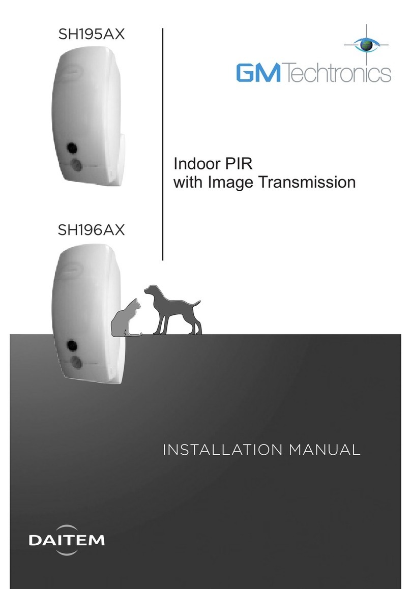
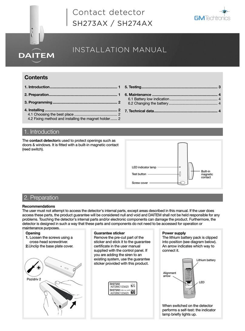
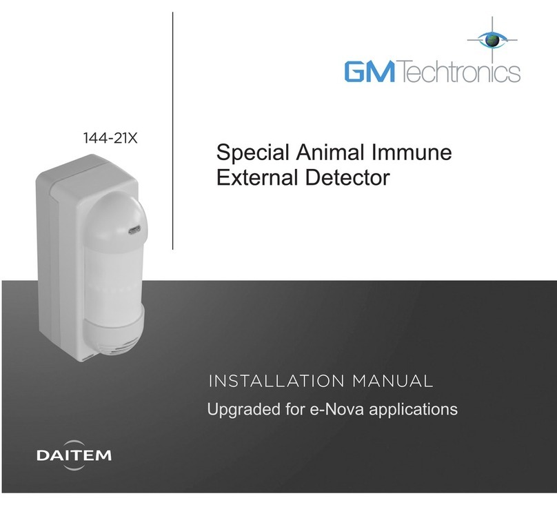
DAITEM DP1101 User manual

www.absolualarme.com met à la disposition du public, via www.docalarme.com, de la documentation technique dont les références, marques et logos, sont la propriété des détenteurs respectifs
F - Détecteur
de mouvement
......................
2
......................
8
....................
14
D - Bewegungsmelder
GB - Motion detector
DP1101
803347/A - Daitem - 09/03
Document non contractuel, soumis à modifications sans préavis.
inweis: Änderungen der technischen Daten und des Designs aufgrund von Produktverbesserungen
bleiben uns ohne Ankündigung vorbehalten.
Non-binding document, subject to modification without notice.
Declaration of conformity to the R&TTE directives 99/5/EC
Manufacturer: ATRAL S.A., rue du Pré de l’Orme, F-38926 Crolles Cedex, France
Atral radio equipments are in conformity with the following european directives:
- R and TTE Directive 99/5/EC,
- Electromagnetic Compatibility Directive 89/336/EEC,
- Low Voltage Directive 73/23/EEC,
and the harmonised European Standards notified under these directives:
- EN 300 220-3 (Spectrum Respect),
- EN 300 683 or EN 301489-1 (EMC Conformity),
- EN 55022 and EN 55024,
- EN 60950 (Electrical Security).
These products can be used in all the EU and EEA countries and Switzerland.
Crolles, January the 14th 2003

www.absolualarme.com met à la disposition du public, via www.docalarme.com, de la documentation technique dont les références, marques et logos, sont la propriété des détenteurs respectifs
3
F
2
F
●en présence d’un obstacle entre le détecteur et la zone à protéger
(meuble, mur, pilier...) qui gènerait la détection.
●Un tournevis cruciforme.
●Une perceuse avec un foret béton Ø 6 mm.
●La pile (fournie).
●Les accessoires de fixation (fournis) : 1 rotule, 1 contre-rotule, 1 vis
longue, 1 cheville, 1 rondelle.
IG. A Vue face
➀ Lentille de détection. ➁ Touche test.
IG. B Ouverture
Ouvrez le boîtier du détecteur en poussant l'ergot de verrouillage ➂avec
un tournevis plat.
IG. C Vignette de garantie
●Détacher la partie prédécoupée amovible de la vignette de garantie et la
coller sur le bon de garantie fourni avec la centrale (une vignette doit rester
sur le produit).
●Si vous complétez un système, utilisez la demande d'extension gratuite
de garantie fournie avec ce produit.
IG. D Alimentation
Connectez la pile.
IG. D et ECodage du détecteur
Le codage du détecteur se fait par programmation à l’aide du voyant de
programmation et des touches 0 et 1.
Vous allez programmer par appuis successifs (sur les touches 0 et 1) le
code installation, puis la zone affectée au détecteur et la sensibilité de
détection.
●Programmation du code installation (fig. D)
Effectuez le codage du détecteur après avoir codé la centrale.
Lorsque vous sortez le détecteur de son emballage, le code installation
programmé correspond à tous les micro-interrupteurs sur ON.
Mise en œuvre
Matériel nécessaire
■Le détecteur de mouvement surveille en permanence l'intérieur de l'ha-
bitation. Il détecte le rayonnement infrarouge émis naturellement par le
corps de l'intrus se déplaçant dans l'espace protégé. L'espace protégé par
ce détecteur est limité par les murs de la pièce dans laquelle il est fixé.
●Transmissions radio TwinPass®
●Programmation par 2 touches spécifiques :
- du code installation
- de la zone et de la sensibilité
●24 faisceaux, portée 12 m avec un angle de 75° à 90°
●Affectation :
- à la zone 1 : déclenchement immédiat
- à la zone 2 : déclenchement retardable
- à la zone 3 : déclenchement immédiat
- à la zone 4 : déclenchement retardable
●Touche test et voyants rouges permettant :
- le contrôle de l'état de la pile
- la visualisation de l'espace protégé
- le contrôle de la liaison radio
- le contrôle de la programmation
- le contrôle de la zone choisie
●Autoprotection à l'ouverture 24 h/24
●Alimentation par pile lithium 3,6 V fournie
●Autosurveillance de l’alimentation
■Installez-le :
●à l'intérieur de l'habitation,
●en hauteur (2,20 m environ),
●de manière à ce que son espace protégé ne croise pas celui d'un autre
détecteur de mouvement (voir Fig. I),
●perpendiculairement aux issues à protéger (voir Fig. I),
●dans les pièces à risque (salon, chambre des parents...) il est préférable
de protéger l'accès à la centrale par un détecteur de mouvement,
■Ne l'installez pas :
●en face ou au-dessus d'une surface pouvant s'échauffer rapidement
(convecteur électrique, cheminée, ventilation),
●en face d'une baie vitrée, cheminée
●directement sur une paroi métallique,
●orienté vers l’extérieur de l’habitation,
Précautions d’installation
Caractéristiques
Fonctionnement
Attention : n'appuyez pas sur la touche de test pendant la phase de
programmation.

www.absolualarme.com met à la disposition du public, via www.docalarme.com, de la documentation technique dont les références, marques et logos, sont la propriété des détenteurs respectifs
système d’alarme fourni avec la centrale.
Appuyez brièvement sur la touche test du détecteur et vérifiez que la centrale émet
un message sonore en allumant le voyant correspondant à la zone.
Si la centrale ne réagit pas comme prévu, reprenez d’abord le codage du détec-
teur. Si le problème persiste, reprenez le codage de la centrale et essayez à nou-
veau. Vous avez affecté le code installation au détecteur.
●Programmation de la zone et de la sensibilité (fig. D)
Le détecteur est affecté en usine à la zone 1 avec une sensibilité normale.
Vous pouvez modifier cette affectation selon le tableau ci-dessous.
Le dernier chiffre du code de la zone permet de choisir la sensibilité :
- pour une sensibilité maximale (le détecteur émet l'information d'intrusion dès
la première détection.
- pour une sensibilité normale (le détecteur émet l'information d'intrusion après
la seconde détection : permet d'éviter les fausses alarmes dans les grandes pièces).
Programmez le code choisi (succession de 3 chiffres composée de “0” et de “1”) en
effectuant des appuis sur les touches 0 et 1 du détecteur comme indiqué ci-dessous.
1
5
F
4
F
Cochez sur la 1re ligne du tableau ci-dessous les cases correspondant
au code installation de la centrale (n° des micro-interrupteurs sur OFF).
Ecrivez sur la 2eligne un “0” (zéro) au-dessous de chaque croix.
Complétez les cases vides de la 2eligne par des “1” (un).
Exemple (à ne pas reproduire) : vous avez positionné les micro-interrup-
teurs 2, 7 et 8 sur OFF.
Vous obtenez une succession de 10 chiffres composée de “0” et de “1” cor-
respondant au code à programmer sur le détecteur.
Attention : le code 0000000000 est déconseillé !
Programmez le code installation en effectuant des appuis sur les
touches 0 et 1 du détecteur comme indiqué ci-dessous.
Exemple pour programmer le code 1011110011 : après un appui simulta-
né du début de programmation, appuyez successivement sur 1, 0, 1, 1, 1,
1, 0, 0, 1, 1 et terminez par un appui simultané de fin de programmation.
Test du code installation (fig. E)
Si vous complétez votre système, vous devez au préalable passer la centrale en
mode test pour effectuer ce test. Reportez vous alors au guide d’installation du
5
4
3
2
1
12345678910
code installation XXX
code détecteur
12345678910
code installation XXX
code détecteur
1011110011
0
{
Appui simultané
jusqu’à ce que le
voyant de
programmation
s’éteigne.
Appui simultané jusqu’à ce
que le voyant s’éteigne. Le
voyant s’éclaire ensuite 5 s
pour signaler une
programmation correcte
10 appuis courts successifs
correspondant au code radio à
programmer. Le voyant
s’éclaire à chaque appui.
▲
01
50744540001
07/95
01
50744540001
07/95
Début de programmation Fin de programmation
Programmation
{
1er appui simultané
jusqu’à ce que le
voyant de
programmation
s’éteigne.
2e appui simultané
jusqu’à ce que le
voyant s’éteigne.
Appui simultané jusqu’à ce
que le voyant s’éteigne. Le
voyant s’éclaire ensuite 5 s
pour signaler une
programmation correcte
3appuis courts
successifs
correspondant
au code à
programmer.
Le voyant s’éclaire
à chaque appui.
▲
Début de programmation Fin de programmation
Programmation
01
50744540001
07/95
01
50744540001
07/95
01
50744540001
07/95
Attention : si au cours de la manipulation vous attendez plus de
7 secondes entre 2 appuis, si l’appui sur 0 et 1 en début ou en fin de pro
grammation n’est pas simultané ou assez long, vous sortez alors du
mode programmation : le voyant clignote, la programmation est incorrec
te. Le code initialement programmé est conservé. Recommencez l’opé
ration depuis le début.
1 1 0
1011110011
1
Déclenchement immédiat
Sensibilité maximale
Zone 1
Déclenchement immédiat ou retardé
Zone 2
Déclenchement immédiat
Zone 3
Déclenchement immédiat ou retardé
Zone 4
Zone Fonctionnement Code
de la zone
Choix
de la sensibilité
000
Sensibilité normale
001
Sensibilité maximale
010
Sensibilité normale
011
Sensibilité maximale
100
Sensibilité normale
101
Sensibilité maximale
110
Sensibilité normale
111

www.absolualarme.com met à la disposition du public, via www.docalarme.com, de la documentation technique dont les références, marques et logos, sont la propriété des détenteurs respectifs
7
F
6
F
Exemple pour programmer la zone 4 avec une sensibilité maximale : après les 2
appuis simultanés du début de programmation, appuyez successivement sur 1,
puis 1, puis 0 et terminez par l’appui simultané de fin de programmation.
Test de la zone choisie (fig. E)
Appuyez longuement (durée approximative : 7 s) sur la touche test du
détecteur jusqu’à extinction du voyant test. Il va alors clignoter 1 à 4 fois
selon la zone programmée. Exemple : le voyant test clignote 4 fois si vous
avez programmé la zone 4. Si le détecteur ne réagit pas comme prévu,
reprenez la programmation de la zone désirée.
Vous avez affecté au détecteur la zone choisie. Si vous désirez changer
cette zone ultérieurement, vous devrez recommencer l’opération de pro-
grammation de la zone et de la sensibilité.
IG. , G et Hixation
Pour des raisons de sécurité et de durée de vie de la pile du détec-
teur, le montage du pion d'autoprotection est obligatoire. En cas
d'oubli ou de montage incorrect du pion, le voyant rouge clignote en
permanence quand le détecteur est clipsé sur son socle.
■ixation sur rotule (fig. )
●Positionnez au mur l’embase ➁à l’endroit choisi pour repérer les 2 trous
de perçage.
●Percez le mur.
●Insérez la vis-tige ➀ dans l’embase et fixez l’embase.
●Positionnez le capot de l’embase ➂.
●Insérer la rotule ➃dans la vis-tige.
●Positionnez le socle du détecteur de mouvement (une figurine indique le
haut du socle).
●Vissez la vis de serrage ➄sans forcer de façon à pouvoir ajuster l’orien-
tation du détecteur de mouvement.
●Détachez le pion n° 3 de la grappe ➅.
●Positionnez le pion d’autoprotection dans son emplacement.
●Positionnez le détecteur de mouvement sur son socle et orientez-le
approximativement.
■ixation en angle (fig. G)
●Pré-percez le socle du détecteur de mouvement pour une fixation en
angle.
●Positionnez le socle au mur à l’endroit choisi pour repérer les trous de
perçage (une figurine indique le haut du socle).
●Percez le mur et fixez le socle.
●Détachez le pion n° 2 de la grappe ➅.
●Positionnez le pion d’autoprotection dans son emplacement.
●Positionnez le détecteur de mouvement sur son socle.
■ixation à plat (fig. H)
●Pré-percez le socle du détecteur de mouvement pour une fixation à plat.
●Positionnez le socle au mur à l’endroit choisi pour repérer les trous de
perçage (une figurine indique le haut du socle).
2
●Percez le mur et fixez le socle.
●Détachez le pion n° 1 de la grappe ➅.
●Positionnez le pion d’autoprotection dans son emplacement.
●Positionnez le détecteur de mouvement sur son socle.
IG. I Test
Représentation de la portée et de l'espace protégé.
Appuyez brièvement sur la touche test du détecteur pour le mettre en
mode test. Le voyant test s'éclaire durant l'appui, une période de test de
1 minute 30 secondes est enclenchée. Passez une ou plusieurs fois
devant le détecteur : le voyant test s'allume pour signaler chaque détec-
tion. Concernant la fixation sur rotule (fig. F), si l'orientation du détecteur
ne vous satisfait pas vous pouvez l'améliorer grâce à sa rotule multidirec-
tionnelle. Une fois le réglage d’orientation terminé ouvrez le boîtier du
détecteur et bloquez la rotule sans trop forcer. Si les sirènes se déclen-
chent, envoyez un ordre d’arrêt avec une télécommande ou un clavier.
Après la période de test, le détecteur se mettra en fonctionnement nor-
mal, le voyant test ne s'éclairera plus lors de chaque détection de mou-
vement, et le détecteur n'enverra des signaux radio à la centrale qu'à
chaque détection et au maximum toutes les 1 minute 30 secondes.
Faites un essai réel du détecteur avec le système d’alarme (cf NOTICE
D'INSTALLATION, chapitre 6).

www.absolualarme.com met à la disposition du public, via www.docalarme.com, de la documentation technique dont les références, marques et logos, sont la propriété des détenteurs respectifs
9
D
8
D
●Gegenüber von Spiegeln und Fenstern
●Auf die Außenwände gerichtet
●Direkt auf Metallflächen
●So, dass ein Gegenstand (z. B. Möbel, große Pflanze, etc.) zwischen
dem Melder und dem zu überwachenden Bereich liegt.
●Einen Kreuzschlitz-Schraubendreher 3 oder 4 mm
●Einen Steinbohrer mit 6 mm Durchmesser
●Die mitgelieferte Batterie
●Das mitgelieferte Montagezubehör: 1 Kugelgelenk, Sockelplatte, 1 lange
Schraube, 1 Dübel, 1 Unterlegscheibe
BILD A Vorderansicht
➀ Detektionslinse. ➁ Test-Taste
BILD B Öffnen
Öffnen Sie das Gehäuse, indem Sie mit einer Münze leicht gegen die
alteklammer drücken ➂.
BILD C Garantieaufkleber
■Bringen Sie den oberen Teil des Garantieaufklebers (im Gerät) auf der
Garantiekarte an. Der untere Teil des Aufklebers bleibt im Gerät.
●Sie installieren das System neu: Verwenden Sie die Garantiekarte, die
der Bedienungsanleitung des gesamten Systems beiliegt.
●Sie erweitern eine bereits bestehende Anlage: Verwenden Sie die
Garantiekarte, die diesem Produkt beiliegt.
■Sollte keine Garantiekarte mitgeliefert werden, so wenden Sie sich an
Ihren ändler, bei welchem Sie die Anlage erworben haben.
BILD D Einsetzen der Batterie
Klipsen Sie die Batterie in den Batteriehalter ein. Achten Sie dabei auf die
richtige Polung.
BILDER D und EPersonalisierung
Personalisieren Sie Ihren Melder mit ilfe der beiden Tasten 0 und 1.
Programmieren Sie nun Ihren geheimen Anlagencode durch aufeinander-
folgendes Drücken der Tasten 0 und 1. Legen Sie dann die Betriebsart des
Melders fest.
●Programmieren des Anlagencodes (Bild D)
Achten Sie darauf, dass die Zentrale schon codiert ist, bevor Sie dem
Melder den Anlagencode zuweisen.
Die werksseitige Codierung des Bewegungsmelders ist 1111111111.
Inbetriebnahme
Sie benötigen
■Der Passiv-Infrarot-Bewegungsmelder dient zur Überwachung von
Innenräumen, z. B. Wohnräume, Diele und Keller. Er erkennt die schnelle
Veränderung der Infrarotstrahlung in seinen Detektionszonen und nimmt
somit ein unbefugtes Betreten des Überwachungsbereiches wahr. Per
Funk wird das Signal an Ihre Zentrale übertragen. Der Überwachungsbe-
reich ist durch die Wände des Raumes begrenzt.
●2-Frequenz-Übertragungsverfahren
●Linie, Anlagencode und Betriebsart personalisierbar, die Eingabe erfolgt
über 2 spezielle Tasten
●24 Doppelzonen auf 3 Ebenen mit 12 Metern Reichweite und 75/90° Öff-
nungswinkel
●Betriebsart:
- auf Linie 1: Alarmbereit bei Teil und Gesamt Ein für Sofortauslösung
- auf Linie 2: Alarmbereit bei Teil und Gesamt Ein für verzögerbare
Auslösung
- auf Linie 3: Nicht in Betrieb bei Teil Ein Alarmbereit bei Gesamt Ein für
Sofortauslösung
- auf Linie 4: Nicht in Betrieb bei Teil Ein Alarmbereit bei Gesamt Ein für
verzögerbare Auslösung
●Test-Taste und LED ermöglichen:
- die Anzeige des Überwachungsbereichs
- die Auslösung des Funktests zur Reichweitenermittlung
- die Kontrolle der Funkverbindung
- die Überprüfung der Programmierung des Anlagencodes
- manuelles Abfragen des Batteriezustandes
●personalisierbarer Anlagencode
●Ständige Überwachung auf unbefugtes Öffnen des Gehäuses durch
Deckelkontakt
●mindestens 2 Jahre Batteriebetriebszeit durch mitgelieferte Batterie.
■Montieren Sie den Bewegungsmelder wie folgt:
●Im Innenbereich des Objektes
●Möglichst in ca. 2,20 m öhe
●Der Überwachungsbereich sollte sich nicht mit dem eines anderen
Melders kreuzen. Die Zentrale sollte sich im Überwachungsbereich eines
Bewegungsmelders befinden (Bild I).
●Der Raum muss parallel zum Melder durchschritten werden können (Bild I).
■Montieren Sie den Bewegungsmelder generell nicht wie folgt:
●In der Nähe von Wärmequellen, wie z. B. elektrischen eizkörpern,
eizstrahlern, Kaminzügen und eizlüftern
Besondere Montagehinweise
Arbeitsweise
Beschreibung
Vorsicht: Achten Sie darauf, dass Sie während der Programmierung
nicht die Test Taste drücken.
www.absolualarme.com met à la disposition du public, via www.docalarme.com, de la documentation technique dont les références, marques et logos, sont la propriété des détenteurs respectifs
grammieren Sie den Melder erneut. Falls das Problem andauert, führen Sie
nochmals die Codierung der Zentrale durch, und wiederholen Sie den Test
●
Programmieren der Linie und der Sensibilität des Melders (Bild D)
Bei Inbetriebnahme ist der Melder werksseitig auf die “Linie 1” und “normale
Empfindlichkeit” programmiert. Sie können diese Einstellung beibehalten oder
gemäß folgender Tabelle ändern. Die letzte Ziffer des Codes legt die Sensibilität
fest:
- für hohe Sensibilität (Übermittlung nach der 1. Detektion)
- für normale Sensibilität (Übermittlung erst nach der 2. Detektion; zum
Vermeiden von Fehlarmen in grösseren Räumen).
Weisen Sie dem Melder die gewünschte Betriebsart zu, indem Sie den
entsprechenden Code programmieren (dreistellige Folge aus “0” und “1”).
Geben Sie hierzu die nachstehende Tastenfolge ein
1
11
D
10
D
Setzen Sie in die 1. Zeile der folgenden Tabelle Kreuze gemäß des
Anlagencodes der Zentrale (für alle Schalter, die auf OFF stehen).
Zeichnen Sie in die 2. Zeile der Tabelle unter jedes Kreuz eine "0" (Null).
Füllen Sie dann die leeren Kästchen der Tabelle mit “1” (Eins).
Beispiel (bitte nicht nachahmen): Sie haben die Schalter 2, 7 und 8 auf
OFF gestellt.
Sie erhalten eine zehnstellige Folge von “0” und “1”: Dies ist der zu pro-
grammierende Code des Bewegungsmelders.
Hinweis: Die Codes “0000000000” und “1111111111” sind nicht zulässig.
Personalisieren Sie Ihren Melder dann durch Drücken der Tasten wie folgt:
Überprüfung des Anlagencodes (Bild E)
Bei einer Anlagenerweiterung muss die Zentrale zuerst in den Testmodus versetzt
werden (Deckel offen). Details hierzu auf S. 26 der Montageanleitung der Zentrale.
Drücken Sie kurz die Test-Taste des Melders, und vergewissern Sie sich, dass die
zuvor codierte Zentrale ein akustisches Signal abgibt und die LED der entspre-
chenden Linie aufleuchtet. Sollte die Zentrale nicht wie beschrieben reagieren, pro-
5
4
3
2
1
12345678910
Anlagencode der Zentrale XXX
Code des Bewegungsmelders
12345678910
Anlagencode der Zentrale XXX
Code des Bewegungsmelders
1011110011
0
{
Gleichzeitiges
Drücken,
bis die LED
erlischt.
Gleichzeitiges Drücken, bis die
LED erlischt. Die Anzeige leuch-
tet danach 5 Sek. lang, um die
korrekte Programmierung zu
bestätigen.
10er-Folge der Tasten 0 oder 1
gemäß Ihrer Personalisierung.
Die rote LED blitzt bei
jedem Tastendruck kurz auf.
▲
01
50744540001
07/95
01
50744540001
07/95
Beginn der Programmierung Ende der Programmierung
Programmierung
{
Beide Tasten
gleichzeitig drücken,
bis die LED
erlischt.
Nochmals beide
Tasten gleichzeitig
drücken, bis die
LED erlischt.
Beide Tasten wieder
gleichzeitig drücken,
bis die LED erlischt.
Die korrekte Programmierung
wird durch erneutes
Aufleuchten der LED
(5 Sek. lang) bestätigt.
Eingabe des 3stelligen
Codes durch kurzes
aufeinanderfolgendes
Drücken von 0 oder 1.
Die LED blitzt
bei jedem
Tastendruck auf.
▲
Programmierbeginn Programmierende
Programmierung
01
50744540001
07/95
01
50744540001
07/95
01
50744540001
07/95
Vorsicht: Wenn während der Programmierung mehr als 7 Sek. zwi
schen aufeinander folgendem Tastendruck vergehen oder 0 und 1 nicht
gleichzeitig gedrückt werden (nur beim Beginn und Ende der Codierung),
wird die Programmierung verworfen. Die rote LED blinkt, um eine fehler
hafte Programmierung anzuzeigen. Bitte führen Sie die Codierung in die
sem Fall nochmals vollständig durch.
1 1 0
1011110011
1
aktiv bei Teil und Gesamt Ein
für sofortige Alarmauslösung
hoch
1
aktiv bei Teil und Gesamt Ein
für verzögerbare Alarmauslösung
2
nur aktiv bei Gesamt Ein
für sofortige Alarmauslösung
3
nur aktiv bei Gesamt Ein
für verzögerbare Alarmauslösung
4
Linie
Betriebsart des Melders zu program-
mierender Code Empfindlichkeit
normal
001
hoch
010
normal
011
hoch
100
normal
101
hoch
110
normal
111
000

www.absolualarme.com met à la disposition du public, via www.docalarme.com, de la documentation technique dont les références, marques et logos, sont la propriété des détenteurs respectifs
13
D
12
D
Beispiel für das Programmieren der Linie 4: Nachdem Sie zweimal gleich-
zeitig die Tasten 0 und 1 für den Programmierbeginn gedrückt haben,
drücken Sie nacheinander 1, dann 1 und dann 0. Beenden Sie die
Programmierung dann durch erneutes gleichzeitiges Drücken beider
Tasten und achten Sie darauf, ob die LED 5 Sek. lang als Bestätigung auf-
leuchtet.
Überprüfen der zugeordneten Linie (Bild E)
Drücken Sie die Test-Taste des Melders etwa 7 Sek. lang, bis die LED
erlischt. Sie blinkt dann ein- bis viermal, je nach zugeordneter Linie.
Führen Sie die Programmierung andernfalls nochmals durch.
Beispiel: Die LED blinkt dreimal, wenn Sie den Melder auf die Linie 3 pro-
grammiert haben.
Sie können dem Melder jederzeit eine andere Linie zuweisen, indem Sie
die neue Linie wie vorher beschrieben (nach Öffnen des Gehäuses) ein-
programmieren.
BILDER , G und HEndmontage
Aus Sicherheitsgründen und um die Batteriebetriebszeit
nicht zu beeinträchtigen muss der Sabotagestößel des Melders mon-
tiert werden. Andernfalls bzw. bei falscher Montage blinkt die rote
LED ständig auf, sobald der Melder auf seinen Sockel gesetzt wird.
■
Befestigung mit Kugelgelenk
(BILD )
●Die Sockelplatte an den vorgesehenen Montageort halten und die bei-
den Befestigungspunkte markieren ➁.
●Die beiden Löcher bohren.
●Die Gewindeschraube ➀in die Sockelplatte einführen und diesen befes-
tigen.
●Den Gehäusedeckel aufsetzen ➂.
●Das Kugelgelenk ➃in die Gewindeschraube einsetzen.
●Das Unterteil des Bewegungsmelders positionieren (ein Symbol zeigt die
korrekte Ausrichtung).
●Die Befestigungsschraube ➄erst leicht anziehen, um den Melder noch
ausrichten zu können.
●Den Sabotagestößel Nr. 3 vom mitgelieferten ➅Zubehörteil ablösen und
an die vorgesehene Stelle platzieren.
●Dann den Melder auf seinen Sockel setzen und ungefähr ausrichten.
■
Eckmontage
(BILD G)
●Den Sockel des Melders für die Eckmontage vorbohren.
●Den Sockel an die vorgesehene Montagestelle halten, um die
Bohrpunkte anzubringen (hierzu Symbol für Sockeloberteil beachten).
●Dann die Löcher bohren und den Sockel befestigen.
●Den Sabotagestößel Nr. 2 ablösen und an die vorgesehene Stelle brin-
gen.
●Dann den Bewegungsmelder auf seinen Sockel setzen.
2
■
Wandmontage
t (BILD H)
●Den Sockel des Melders für die Wandmontage vorbohren.
●Den Sockel an die vorgesehene Montagestelle halten, um die
Bohrpunkte anzubringen (hierzu Symbol für Sockeloberteil beachten).
●Dann die Löcher bohren und den Sockel befestigen.
●Den Sabotagestößel Nr. 1 ablösen und an die vorgesehene Stelle brin-
gen.
●Dann den Bewegungsmelder auf seinen Sockel setzen.
BILD I Test
Prüfen der unkreichweite und des Überwachungsbereiches:
Betätigen Sie die Test-Taste, um den Melder in den Testmodus zu schal-
ten. Die LED ist aktiv, solange Sie die Taste betätigen. Danach bleibt der
Melder selbsttätig für 1,5 Minuten im Testmodus. Betreten Sie nun mehr-
mals den überwachten Bereich des Melders. Jede Detektion wird durch
das Leuchten der LED angezeigt, und ein Funksignal wird abgeschickt.
Durch das Kugelgelenk können Sie den Melder so drehen oder neigen,
dass ein idealer Detektionsbereich eingestellt ist. Danach öffnen Sie den
Melder noch einmal und zeihen die Schraube erst jetzt fest. Wenn die
Sirenen auslösen, können Sie diese mit der Taste Aus der Fernbedienung
abstellen.
Nach der Testphase setzt sich der Melder automatisch in den
Normalbetrieb zurück. Die LED zeigt keine Detektion mehr an, und
der Melder kann maximal alle 1,5 Minuten ein unksignal absenden.
Lösen Sie, wie in der Montage-Anleitung der Zentrale beschrieben, einen
echten Alarm aus.
Wenn die LED des Melders nach Betätigen der Test-Taste nicht mehr auf-
leuchtet, muss die Batterie gewechselt werden.
Batteriewechsel

www.absolualarme.com met à la disposition du public, via www.docalarme.com, de la documentation technique dont les références, marques et logos, sont la propriété des détenteurs respectifs
14 15
GB GB
●where there is an obstacle (furniture, wall, pillar,...), which might prevent
detection, between the detector and the area to be protected.
●A cruciform screwdriver
●A drill with 6 mm Ø concrete bit
●The battery (supplied)
●The fixing accessories supplied: 1 ball and socket joint, 1 long screw,
1 dowel, 1 washer.
IG. A ront view
➀ Detection lens. ➁ Test button.
IG. B Opening
Open the detector casing by pushing the locking pin ➂with a flat screw-
driver.
IG. D Power supply
Connect the battery.
IG. D and EDetector coding
The detector is coded by programming using the programming indicator
light and keys 0 and 1.
Programme first your installation radio code and then the zone assigned to
the detector and the detection sensitivity by pressing keys 0 and 1 in turn.
●Programming the installation radio code (fig. D)
You should code the control panel before the detector.
When you take the detector out of its packing, the installation radio code
correspond to the ten microswitches of the control panel all in ON position.
Implementation
You will need
■The motion detector constantly monitors the interior of the home. It
detects the infrared radiation naturally emitted by the body of the intruder
moving around in the protected area. The area protected by this detector is
limited by the walls of the room in which it is installed.
●Dual requency radio transmission
●Programming by 2 specific keys:
- of the installation radio code
- of the zone and sensitivity
●24 beams, 12 meters range with an angle of 75-90°
●Allocation:
- to zone 1: immediate triggering
- to zone 2: immediate or delayed triggering
- to zone 3: immediate triggering
- to zone 4: immediate or delayed triggering
●Test key with light indicator to check:
- the protected area
- the chosen zone
- programming
- radio link
- battery state
●24 hour tamper protection against lid removal
●round-the-clock tamper-proof function
●Supplied by 3.6 V lithium battery (supplied)
■Install it:
●inside the home,
●high up (approx. 2.20 meters),
●so that the protected area does not overlap that of another motion detector,
It is recommended to protect the access to the control panel with a motion
detector (see fig. I).
●in high risk areas (lounge, main bedroom, etc.),
●perpendicular to the entrances to be protected (see fig. I).
■Do not install it:
●opposite or above a surface that can heat up quickly (electric convector,
fireplace, ventilator),
●opposite a bay window,
●directly on a metal surface,
●directed towards the outside of the home,
Installation precautions
Characteristics
Operation
Caution: do not press the test key while programming.

www.absolualarme.com met à la disposition du public, via www.docalarme.com, de la documentation technique dont les références, marques et logos, sont la propriété des détenteurs respectifs
If the control panel does not properly respond, first recode the detector.
Then if the problem persists, recode the control panel and try again.
You have now assigned the detector its installation radio code.
●Programming the zone and sensitivity (fig. D)
The zone 1 detector is factory-set to normal sensitivity.
These settings can be modified in accordance with the table below.
The last digit of the code allows the sensitivity to be set:
-
for maximum sensitivity
(the detector transmits the intrusion alarm on the
first detection)
-
for normal sensitivity
(the detector transmits the intrusion alarm after the
second detection: avoids false detections in large rooms).
Assign the detector the chosen zone by programming the relevant code
(series of 3 digits made up of "0" and "1"), pressing the keys as shown
below:
1
16 17
GB GB
On the 1st line of the table below tick the boxes corresponding to the
installation radio code of the control panel (a cross for each microswitches
in OFF position).
On the 2nd line mark “0” (zero) below each tick.
Enter “1” (one) in the empty boxes on the 2nd line.
Example (not to be used): the switches 2, 7 and 8 are in OFF position.
You now have a series of 10 digits made up of “0” and “1” corresponding to
your detector’s installation radio code.
Warning: code 0000000000 is not recommended.
Programme the radio code by pressing keys 0 and 1 on the detector as
shown below:
Installation radio code test (fig. E)
If you are adding to your system, you should first activate the system’s test
mode to carry out this test. To do this, refer to the installation guide for the
alarm system provided with the unit.
Briefly press the detector’s test button and check that the unit emits an
audio message while lighting up the indicator corresponding to the zone.
5
4
3
2
1
12345678910
customised radio code
XXX
detector code
12345678910
customised radio code
XXX
detector code
1011110011
0
{
Press both keys at
the same time until
the light indicator
goes out.
Press both keys at the same time
until the light indicator goes out.
The light indicator then comes
on for 5 sec. to indicate
that programming is OK.
Briefly press the keys 10 times
for your installation radio code.
The red light indicator comes
on each time a key is pressed.
▲
01
50744540001
07/95
01
50744540001
07/95
Start of programming End of programming
Programming
{
Press both keys at
the same time until
the light indicator
goes out.
Press both keys at
the same time
again until the light
indicator goes out
Press both keys at the same time
until the light indicator goes out.
The light indicator then comes
on for 5 sec. to indicate
that programming is OK.
Briefly press the keys
3 times for your
group code. The
light indicator
comes on each time
a key is pressed.
▲
Start of programming End of programming
Programming
01
50744540001
07/95
01
50744540001
07/95
01
50744540001
07/95
Warning: If during programming more than 7 seconds elapse between
pressing 2 keys or if you do not press simultaneously or long enough
keys 0 and 1 at the beginning or end of programming, you will leave the
programming mode. The red light indicator then flashes to show that pro
gramming is not correct. The initially programmed code is kept, and you
must repeat the operation from the beginning.
1 1 0
1011110011
1
Immediate tripping Maximum sensitivity
Zone 1
Immediate or delayed tripping
Zone 2
Immediate tripping
Zone 3
Immediate or delayed tripping
Zone 4
Zone Functionning Group
code
Choice
of sensitivity
000
Normal sensitivity
001
Maximum sensitivity
010
Normal sensitivity
011
Maximum sensitivity
100
Normal sensitivity
101
Maximum sensitivity
110
Normal sensitivity
111

www.absolualarme.com met à la disposition du public, via www.docalarme.com, de la documentation technique dont les références, marques et logos, sont la propriété des détenteurs respectifs
19
GB
18
GB
An example for programming zone 4 with maximum sensitivity: after press-
ing the keys twice at the same time at the start of programming, press 1, 1
again then 0 in turn and finally press both keys again at the end of pro-
gramming.
Testing the chosen zone (fig. E)
Press and hold down the detector's test key for roughly 7 seconds until the
test indicator light goes out. It will then flash 1 to 4 times according to the
programmed zone. For example, the test indicator light will flash 3 times if
zone 3 is program-med. If the detector does not react as you expect,
reprogramme the chosen zone.
You have assigned your detector its chosen zone. If you wish to change
this zone at any stage you must programme the zone and sensitivity pro-
gramming operation.
IG. , G and Hixing
or reasons of security and long battery life of the detector, the ins-
tallation of the anti-tamper pin is obligatory. In case of omission or of
incorrect installation of the pin, the red LED flashes continuously
when the detector is fitted to its bracket or to the wall.
■To fix on an adjustment axis (fig. )
●old the back plate ➁on the wall in the desired position to mark where
to drill the holes.
●Drill the wall.
●Insert the long screw ➀ into the back plate and fasten the back plate to
the wall.
●Put the back plate cover ➂in place.
●Insert the adjustment axis ➃into the long screw.
●Position the base of the movement detector (a figure shows the top of
the base).
●Tighten the securing screw ➄, but not too much, so that the direction of
the movement detector can be adjusted.
●Detach pin n° 3 from the selection supplied ➅.
●Place the anti tamper pin in position.
●Place the movement detector on the base and turn it to approximately
the right angle.
■To fix in a corner (fig. G)
●Select the pre-drilled holes in the base of the movement detector for cor-
ner fixing.
●old the back plate on the wall in the desired position to mark where to
drill the holes (a figure indicates the top of the base).
●Drill the wall and fix the base.
●Detach pin n° 2 from the selection supplied ➅.
●Place the anti tamper pin in position.
●Place the movement detector on the base.
■To fix flat (fig. H)
●Select the pre-drilled holes in the base of the movement detector for
fixing flat.
2
●old the back plate on the wall in the desired position to mark where to
drill the holes (a figure indicates the top of the base).
●Drill the wall and fix the base.
●Detach pin n° 1 from the selection supplied ➅.
●Place the anti tamper pin in position.
●Position the movement detector on the base.
IG. I Test
Representation of the range and area protected.
Press the test button on the detector to put it into the test mode. The red
light indicator comes on while you press, a test period of 1 minute 30 sec-
onds is starting.
Pass in front of the detector once or several times: the red light indicator
comes on to indicate each detection.
About fixing on an adjustment axis (fig. F), if the orientation of the detector
is not ideal, you can improve it thanks to the multi-directional ball and soc-
ket joint. When the orientation is decided, open the detector casing and
block the ball and socket joint without forcing.
If the sirens sound, send an off order using the keypad or a remote control.
After the test period, the detector returns to the normal operating
mode and the light does not come on upon motion detection. The
detector only sends radio signals to the control panel every 1 minute
30 seconds at most.
Carry out a genuine test of the detector using the alarm system (see
Logisty installation guide chapter 6).
The warranty conditions of the motion detector are the same as those
given in the documents supplied with the control panel.
Warranty

www.absolualarme.com met à la disposition du public, via www.docalarme.com, de la documentation technique dont les références, marques et logos, sont la propriété des détenteurs respectifs
A
E
C
123456789012
123456789012
D
01
50744540001
07/95
B
➀
➁➂
Voyant de programmation
Programmier-LED
Programming indicator Light
Connecteur pile
Batteriestecker
Battery connector
a
a
a
a
a
aaaa
a
a
a
a
a
a
aa
a
a
a
a
a
aa
a
a
aa
a
a
a
a
a
a
a
a
a
a
aa
a
a
a
a
a
a
a
a
a
a
a
a
a
a
a
aa
a
a
a
a
a
a
a
a
a
Pion n° 3 pour une fixation sur rotule
Sabotagestößel Nr. 3 für eine Montage mit Kugelgelenk
Pin n° 3 use when fixing with an adjustment axis
➀➄➅➃➂➁

www.absolualarme.com met à la disposition du public, via www.docalarme.com, de la documentation technique dont les références, marques et logos, sont la propriété des détenteurs respectifs
G
2,2 m
2 4 6 8 10 12 m
2,2 m
2 4 6 8 10 12 m
12 m
4 m
8 m
I
H
4 vis de fixation
4 Befestigungspunkte
4 fixing screws
Préperçages
Durchbrüche
Pre-drilled holes
Pion n° 2 pour une fixation en angle
Sabotagestößel Nr. 2 für die Eckmontage
Pin n° 2 use when fixing in a corner
90°
2 vis de fixation
2 Befestigungspunkte
2 fixing screws
Préperçages
Durchbrüche
Pre-drilled holes
Pion n° 1 pour une fixation à plat
Sabotagestößel Nr. 1 für die Wandmontage
Pin n° 1 use when fixing flat
Table of contents
Languages:
Other DAITEM Security Sensor manuals

DAITEM
DAITEM SH273AX User manual

DAITEM
DAITEM SH101AX User manual

DAITEM
DAITEM SH195AX User manual

DAITEM
DAITEM SH271AX User manual

DAITEM
DAITEM 155-21X User manual

DAITEM
DAITEM SH148AX User manual

DAITEM
DAITEM 171-21X User manual

DAITEM
DAITEM 144-21X User manual

DAITEM
DAITEM 191-21X User manual

DAITEM
DAITEM 145-21X User manual