DazeTechnology DazeBox C User manual

DAZEBOXC
Installation Manual

The information contained in this manual is the property of DazeTechnology
and may not be reproduced in whole or in part.
This manual is supplied with the device to the Customer.
DazeTechnology shall not be held liable for any damage that may directly or
indirectly be caused to persons, property or animals due to failure to comply
with all the requirements set out in this manual.
© Copyright 2021 DazeTechnology
All rights reserved
www.dazetechnology.com
Manual in English rev.0
2

3

SUMMARY
SUMMARY 3
1. INTRODUCTION 5
1.1. Manual warning 5
1.2. Useful documentation 6
1.3. Used symbols 6
1.4. Abbreviations 6
1.5. Terminology 7
2. SAFETY INFORMATION 8
3. DESCRIPTION 10
3.1. Wallbox description 10
3.2. DazeBox C models 10
3.3. Nameplate 11
3.4. Technical specifications 12
3.5. Power Management and Solar Boost (optional) 15
3.6. Daze App Matching 16
4. INSTALLATION 17
4.1. Choice of the installation site 17
4.2.Packaging 19
4.3. Transport and preliminary check 19
4.4. Protection and power supply of the charging station 20
4.5. Assembly 27
4.6. Single-phase DazeBox electrical connection 32
4.7. Three-phase DazeBox electrical connection 35
4.8. Three-phase DazeBox electrical connection on single phase system 38
4.9. Single-phase DazeBox on three phase system 38
4.10. Release coil connection 39
4.11. Configuration guide 40
4.12. Putting into operation 48
4

1. INTRODUCTION
1.1. Manual warning
The DazeBox is a charging station (wallbox) for electric vehicles installed in
Charging Mode 3, i.e. with a permanent connection to the electricity grid.
The information in this manual is intended for the installer of DazeBox C
and covers the installation, use and care of the wallbox.
The most recent and up-to-date version of this manual can be found on the
website. The original instructions in this document are in Italian (ITA). All
other versions are translations of the original instructions.
The illustrations in this document show a typical configuration and are
provided for instruction and description purposes only. It is not always
possible to show the configuration of the device in use.
6

1.2. Useful documentation
See the other documents on the site by framing the QR code.
▪DazeBox C Installation Manual
▪EC Declaration of Conformity
▪Drilling template
▪Dynamic Power Management Manual
1.3. Used symbols
7

1.4. Abbreviations
Abbreviation
Definition
AC
Alternating current
DC
Direct current
EMC
Electromagnetic compatibility
EV
Electric Vehicle
EVSE
Electric Vehicle Supply Equipment
PE
Protective earthing
1P
Single-phase
3P
Three-phase
PM
Power Management
1.5. Terminology
Term
Definition
Installer
External contractor contracted by the owner to carry out
technical, civil engineering and electrical installation work
Owner
Legal owner of the wallbox
User
Owner of an electric vehicle (EV) using the EVSE device
to charge the EV
Local regulations
All regulations applicable to the EVSE device during its
entire life cycle. Local regulations include national
8

regulations and laws
Qualified
personnel
Qualified technical personnel for the design,
implementation and certification of domestic electrical
installations in accordance with local regulations and the
energy supply contract
9

2. SAFETY INFORMATION
DazeBox has been developed, manufactured and tested in accordance with
current safety regulations. Therefore, the product does not normally involve
any danger to persons or property. The manufacturer accepts no liability for
any damage to persons or property resulting from failure to observe the
safety regulations and these recommendations.
All installation, maintenance and decommissioning of the product must only
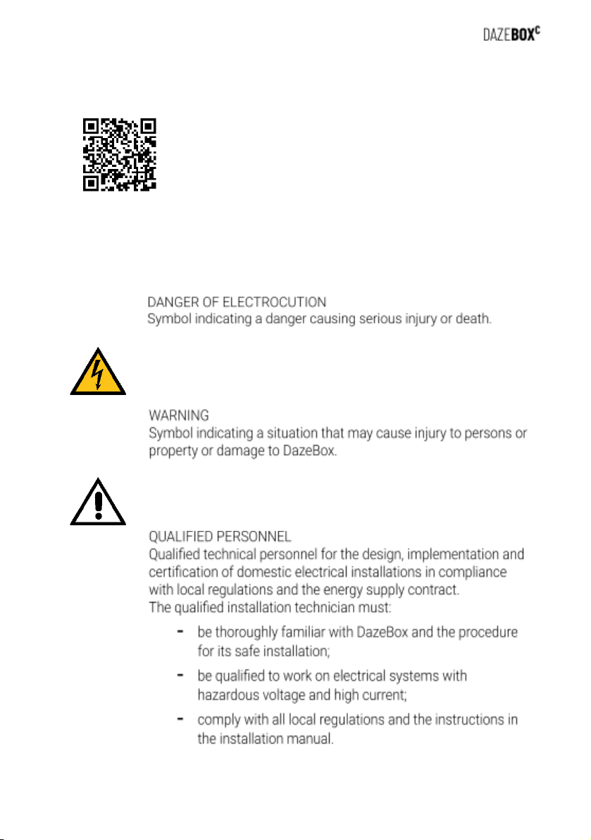
be carried out by qualified and authorised personnel. The qualified
installation technician must:
-be thoroughly familiar with DazeBox and the procedure for its safe
installation;
-be qualified to work on electrical systems with hazardous voltage
and high current;
-comply with all local regulations and the instructions in the
installation manual.
It is the responsibility of the DazeBox owner to ensure that all qualified
installation technicians comply with all local regulations, installation
instructions and product specifications.
10

11

3. DESCRIPTION
3.1. Wallbox description
DazeBox is a device for AC charging of electric or plug-in hybrid vehicles
with a Type 2 charging socket (according to IEC 62196).
DazeBox is designed exclusively for fixed installation, with permanent
connection to the mains, indoors or outdoors, in accordance with the
instructions in Chapter 4 and local regulations.
Charging is carried out in mode 3, in accordance with IEC/EN 61851-1,
which consists of connecting the rechargeable electric or hybrid vehicle to
the AC mains using specific connectors, in accordance with IEC 62196-1
and 2, and the presence of a pilot control circuit within the station to check
the continuity of the protective conductor between the vehicle and the
mains during charging. This control is necessary to ensure that no
hazardous voltage can be discharged through accidental contact by
unaware persons. Mode 3 is therefore recommended for its maximum
degree of safety and also for its ability to deliver high currents.
3.2. DazeBox C models
Two main DazeBox models can be distinguished, depending on customer
requirements:
- DazeBox C DB-07-M, hereafter called DazeBox 1P or DazeBox
single-phase, 230 V with maximum power up to 7.4 kW;
- DazeBox C DB-07-T, hereinafter referred to as DazeBox 3P or DazeBox
three-phase, 400 V with a maximum power output of up to 22 kW.
For technical details and differences between these two types see Section
3.4 - Technical Specifications.
The DazeBox model can be identified by reading the nameplate on the
device. See next paragraph.
12

3.3. Nameplate
The figure above is an example of a DazeBox nameplate.
- In the column from left to right you read:
- Manufacturer
- Manufacturer address
- DazeBox code (PN)
- Serial number of DazeBox (SN)
- Nominal data of DazeBox
- Product name
- CE marking
The nameplate is located on the rear side of the charging station (E, in the
picture below). The data shown may vary depending on the model. In
general, the model is clearly identified by reading the nominal voltage, i.e.
230V for single-phase DazeBox and 400V for three-phase DazeBox.
13

In caso di necessità, per ricevere assistenza è necessario conoscere il
numero seriale (SN) della DazeBox. Dal momento che, una volta installata a
muro, la targhetta posta sul retro non è più raggiungibile, è possibile
identificare ugualmente il numero seriale (SN) estraendo il coperchio
rimovibile frontale; il codice è su una piccola etichetta applicata nella parte
inferiore dell’involucro. È possibile trovare il numero seriale anche sulla
tessera all’interno della confezione.
3.4. Technical specifications
The wallbox casing is made of polycarbonate to ensure high rigidity and
lightness.
14

1 - Casing
2 - Removable cover
3 - Status LED
4 - Charging cable with Type 2 connector
5 - Connector holder
6 - Electrical system with protectors and cables (not included)
15

There are two types of DazeBox for two different charging capacities,
according to customer requirements: single-phase wallbox and three-phase
wallbox.
Description
DazeBox 1P
DazeBox 3P
Model number (PN)
DB-07-M
DB-07-T
EV charging cable
Type 2 (IEC 62196-1, IEC 62196-2)
EVSE standard
IEC 61851-1, IEC 61851-21
CE Marking
Yes
Warranty
2 years
Charging mode
Mode 3
Connector cable length Type 2 [m]
3, 5, 7
5, 7
General specifications
Degree of protection
IP55, IK08 (IEC 60529)
Dimensions [mm]
335 x 277 x 102 (without connector)
335 x 277 x 285 (with connector)
Casing material
polycarbonate
Weight [kg]
~ 4
~ 5
Electrical specifications
Maximum power [kW]
7,4
22
Voltage [V]
230 ±10%
single-phase
400 ±10%
three-phase
Frequency [Hz]
50
16

Current [A]
32
Stand-by consumption [W]
< 2
Network configuration
TT / TN
Protection class
I
Pollution degree
PD2
Overvoltage category
OVC III
Internal protections
continuous current monitoring
residual current > 6 mA DC
Power cable routing
open/under track
Power supply wire cross-section
6 mm2
Environmental specifications
Operating temperature range [°C]
-25 / +50 (without exposure
exposure to direct sunlight)
Storage temperature range [°C]
-30 / +60
Relative humidity
<95%, non-condensing
Maximum installation altitude
2000 m a.s.l.
Overheating protection
Yes
Fire safety
UL94 V-0
Operation
Dynamic Power Management
Yes (optional)
Solar Boost (energy from photovoltaics)
Yes (optional)
No
User interface
Status indicator
RGB LED
Connectivity
Bluetooth, WiFi
User interface
Daze App for Android and iOS
External master communication protocol
Modbus RTU
3.5. Power Management and Solar Boost (optional)
DazeBox can include the Power Management (PM) function, or load
balancing, which allows you to dynamically modulate the power dedicated
to recharging the vehicle so that it does not exceed the contracted power of
the meter, thus preventing it from tripping.
To activate Power Management, the following explains how to install the
current sensor that detects consumption at the meter. DazeBox can also
operate without Power Management; in this case, the installation of a
dedicated sensor is not necessary, but there is no guarantee that blackouts
due to power consumption can be avoided.
17

DazeBox can also include Solar Boost, a function to speed up charging
when there is excess photovoltaic production. If, downstream of the meter,
a generation system via photovoltaic panels is installed, it is recommended
to activate this function for optimal DazeBox operation by following the
instructions below.
The Solar Boost function detects any surplus energy produced (not
consumed internally by the building and transferred to the grid via the
two-way meter) and dedicates it to recharging the vehicle, thus speeding it
up. In order to activate the Solar Boost function, it is essential that the
optional Power Management sensor is correctly installed (see Dynamic
Power Management Manual); in fact, this function is intended as an
extension of the PM in the presence of a photovoltaic system.
18

3.6. Daze App Matching
Daze is a smartphone app useful for monitoring and setting up DazeBox via
Bluetooth.
1. Download the App via Google Play or App Store.
2. Add your DazeBox: enter the Serial Number and PUK of the wallbox.
This data can be found on a card inside the DazeBox package. The
picture below shows the back of the card. Do not miss.
19

4. INSTALLATION
Installation must be carried out by qualified personnel, i.e. with the skills
described in Section 1.5.
If installation is not explicitly included in the sales contract together with the
wallbox, we will gladly assist in finding a qualified installer.
Do not make arbitrary changes to the device. Repairs may only be carried
out by the manufacturer or qualified personnel. Do not remove safety
symbols, warning notices, cable labels or nameplates.
4.1. Choice of the installation site
DazeBox is designed to be installed fixed to the wall. Therefore, it cannot be
moved for use in different environments.
Before proceeding with the installation of the device, the most suitable
installation location must be chosen. The DazeBox installation location
must:
▪tenere conto della posizione dell'attacco di ricarica sul proprio veicolo
e del senso di parcheggio abituale: specialmente per DazeBox dotate
20
Other manuals for DazeBox C
1
Table of contents
Other DazeTechnology Batteries Charger manuals
Popular Batteries Charger manuals by other brands

Eton
Eton Blackout Buddy Connect Charge user manual

Pro-Team
Pro-Team R840083 owner's manual

FRONIUS
FRONIUS Wattpilot Go 11 J 2.0 operating instructions

Silvercrest
Silvercrest 270366 Operation and safety notes

Silvercrest
Silvercrest SLS 2200 C2 operating instructions

Proseries
Proseries PSC-15A-OB owner's manual