DCS LDT-M1 User manual

LDT-M1 User Manual
11/02/2020

LDT- M1 User Manual
2
Introduction
DCS’ LDT-M1 is a lens encoding system for the Arri ALEXA Mini and Mini LF. It reads the Focus,
Iris and Zoom motor movements and translates this information into compatible data for the
host camera. This metadata is then written directly into the ArriRaw camera files in real time.
Please note: LDT-M1 requires a connection to the camera through the LBUS on the lens mount.
If a lens mount is being used which does not have the LBUS connection the LDT-M1 cannot
record metadata. If this is the case contact DCS and ask about the LDT-R1 which can record the
lens data on an SD card.
Please note: LDT-M1 works with the Preston system but in order to create a lens table a WCU-4
handset is required.
LDT-M1 Components
Add image
1
ETH
10-pin 1B Lemo
2
LDE
12-pin S103 Fischer
3
SERIAL
4-pin 0B Lemo
4
MDR
4-pin 0B Lemo
5
CAM
4-pin 0B Lemo
6
CAL
Calibration Button

LDT- M1 User Manual
3
Physical Connections
Name
Type
Description
Cable Codes
ETH
10-pin 1B Lemo
Ethernet to RJ-45
computer
connection
ETHA
LDE
12-pin S103 Fischer
Lens data encoder
connection port for
LDT-E1 and Arri
LDE-1
LDE, LDE-1
embedded cable
SERIAL
4-pin 0B Lemo
Serial passthrough
connection port
CT
MDR
4-pin 0B Lemo
Preston MDR Serial
connection port
MDR, MDRP
CAM
4-pin 0B Lemo
LBUS connection to
camera
LBUS
Cable Types and Codes
All DCS cables are categorized using a code and a bend relief color for each of the cable
types. Cables have two default lengths, 12 or 18 inches and the connector type can be
straight (S), right angle (R), or anglissimo (O). Custom cables can be made upon
request.
Code
Bend
Relief
Color
Type
Port Name
Description
ETHA
Black
10-Pin 1B Lemo
to RJ-45
ETH
ETHA cable connects the LDT-M1 to a
computer for firmware updating.

LDT- M1 User Manual
4
LDE
Green
12-pin S103
Fischer to 6-pin
0B Lemo
LDE
LDE connects the LDT-E1 to the LDT-M1.
CT
Orange
4-pin 0B Lemo to
6-pin 1B Lemo
SERIAL
CT cable connects the Preston MDR 2 or 3
serial port with a CineTape. This cable
connects to the LDT-M1 Serial connector if
the Preston MDR serial ports are in use.
MDR
Blue
4-pin 0B Lemo to
4-pin 0B Lemo
MDR
MDR cable connects the LDT-M1 to a Preston
MDR 2 or 3 serial port.
MDRP
Blue
4-pin 0B Lemo to
4-pin 0B Lemo
MDR
MDRP cable connects the LDT-A1 to a
Preston MDR 2 or 3 serial port. Also provides
power.
LBUS
Red
4-pin 0B Lemo to
4-pin 0B Lemo
CAM
LBUS cable connects LDT-M1 to the LBUS
port of the Alexa Mini / Mini LF camera. It
injects the encoded data into the RAW file.
Setting up the Preston
The Preston MDR must be running firmware 1.15 or later please update your MDR first.
In order to correctly create lens maps, Preston F-Mapping must be disabled. This can be
enabled for normal operation once the maps have been made but it is essential it’s disabled
during setup.
●Press the Menu key,
●Select Lens,
●If the focal length and serial number of a lens appears to the right of
“Lens”, press F-Map OFF,

LDT- M1 User Manual
5
●The HU3 is now ready for basic operation.
Setting up the Alexa Mini
The Camera’s internal lens mount must be disabled in order to use the external LBUS connector.
●Choose MENU > Electronic Control System (ECS) >Lens data > Lens info > Settings,
●Untick ‘Enable lens mount’.
Change ‘Focus unit’ to ‘Imperial’
Overlay Lens Data on a Monitor
In order to display lens data as an overlay on an SDI monitor, do the following:
●Choose MENU > Monitoring > SDI > SDI processing > Overlays > Status components,
●Tick on Lens data.
Rigging the camera
●Connect the LDT-M1 using the MDR Blue Cable from the MDR port on the LDT-M1 to
Serial 1 on the Preston MDR-3,
●Plug the LBUS Red cable from the CAM port on the LDT-M1 to the LBUS Port on the lens
mount of the Alexa Mini,
●Turn off the Arri WCU-4 handset,
●Connect the Preston Hand unit to the MDR,
●Use the calibration button on the LDT-M1 to calibrate the lens. Visually check all active
axes are calibrating,
●This system requires that the MDR is ALWAYS calibrated from the LDT, not the button on
the MDR itself,

LDT- M1 User Manual
6
●Make sure all the axes that are plugged into the MDR are active by operating the Preston
Hand Unit,
●Ensure that the motors are all in the right direction for normal use by the Preston HU3,
Programming a New Lens Table
Creating a lens table is essential to the encoding process. It requires inputting the
relevant lens information (lens name, brand, serial number etc.) and then inputting all of
the marks from each axis (focus/iris/zoom) for each lens. The following guide explains
this process.
Creating a New Lens Table
Mapping a new lens table is crucial to ensuring that the data encoded throughout the
production is precise.

LDT- M1 User Manual
7
When mapping a lens, a methodical process needs to be adopted. As standard practice,
DCS suggests to enter a mark point on the WCU-4 for each engraved mark on the lens
and let the LDS system interpolate the rest of the data.
Ensure that the lens calibration happens without any motor slip. When moving the lens
axis with a remote handset, mark alignment should always be achieved from the same
direction to avoid slack on the lens.
Initial check
Establish which direction will be used on the Preston HU3 for the run of the show (close
focus, infinity, wide open iris, close iris, wide zoom, tight zoom). DCS suggests keeping
it consistent throughout the whole set of lenses.
Switch off the Preston HU3 and connect the WCU-4 to the Alexa Mini. Make sure you can move
the Preston motors connected by operating the WCU-4.
Do not move Preston Motors or change direction while encoding the lenses unless
required by rigging purpose.
Remember to insert an SD card into the slot of the WCU-4 before starting.
Always calibrate the lens from the LDT-M1 calibration button.
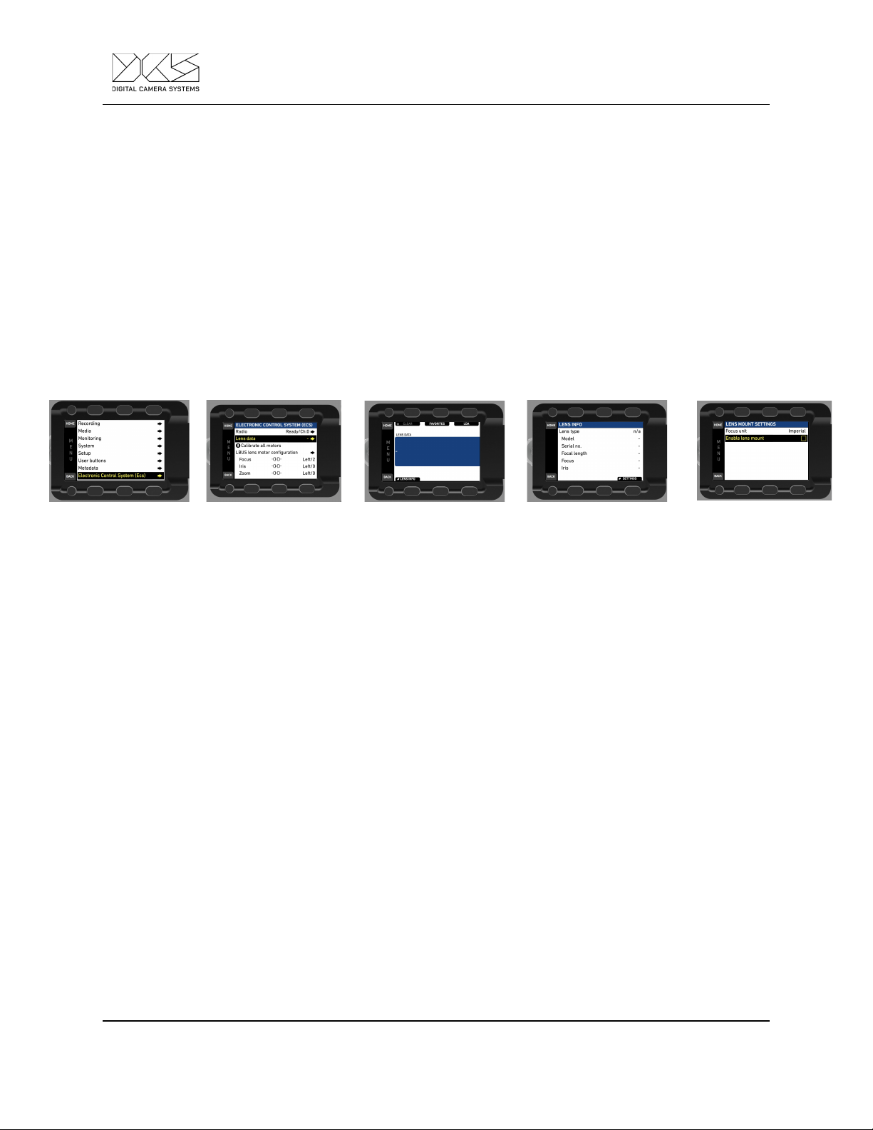
The directions of the Focus, Iris, and Zoom axis on the WCU-4 may have to be changed to match
the direction of the Preston motors. In order to change the motor direction on the WCU-4 or on
the Alexa Mini:
●Choose MENU > Electronic Control System (ECS) > LBUS lens motor configuration,
●Set the configuration for the lens motor. You have the following options:
○Focus/Iris/ Zoom motor torque - Available values in the range of 1 (lowest) to 4
(highest),
○Focus/Iris/Zoom motor direction - Available values are Left and Right,
○Focus/Iris/Zoom motor teeth count - Leave this setting to AUTO.
Do not change the direction of the Preston motors.
Please follow the ARRI WCU-4 User Manual in order to map lenses using the WCU-4.
Adding a New Lens

LDT- M1 User Manual
8
Mount a new lens to the camera. On the LDT-M1 press the calibrate button. On the WCU-4
Choose: MENU > LENS DATA > LENS PROGRAMMING > CREATE LENS FILE.
Select the lens brand, it can either be selected from a list or added manually. Use the up and
down buttons to select from the list, or select custom to enter a custom lens brand name. Press
OK or the user button to confirm the selection.
To enter a custom brand lens use the zoom stick to select characters on the left hand side of
the screen. In order to select a character press the user button. In order to delete a character
press the delete button. When finished press the OK button to select the lens type.
To select a focal length use the up and down buttons or the zoom stick to navigate the list. In
order to enter a custom focal length press custom. For a zoom lens select zoom and then press
OK or user button to confirm.
To enter the lens serial number use the zoom stick to highlight a number and press the user
button to select it. Press the delete button to delete the last number. Press the OK button once
the serial number is complete.
Select the unit of measurement for focus, use the up and down buttons or the zoom stick to
select metric or imperial and then press the OK or User button to confirm.
Mapping a Lens Table
Once all the lens information is entered, select either ‘Focus’, ‘Iris’ or ‘‘Zoom’ (if a Zoom
lens is being used) axis to start mapping the lens.
Mapping The Focus Axis
Use the focus knob to move through the span of the axis, ensuring that it reaches each
end of the lens. If not, check if there were any slips during calibration.
To programme the focus scale press the focus button.
To set the infinity mark for focus rotate the focus knob until the lens reaches infinity. Press the
OK or user button to set the infinity point.
To set the close focus mark. Rotate the focus knob until the lens reaches closed focus. Use the
up and down buttons or zoom stick until the close focus value appears on the screen. Press the

LDT- M1 User Manual
9
OK or the user button to confirm. Now repeat the above steps in order to populate your lens
table. Work through each engraved value on the lens to ensure maximum precision. Use the
Down button to edit any data points.
Once all focus values have been entered press finish to save. Press OK to return to the Select
Axis Screen.
Mapping the Iris Axis
Use the iris slider to move through the span of the axis, ensuring that it reaches each
end of the lens. If not, check if there were any slips during calibration.
Now move onto mapping the Iris by pressing the Iris button.
Set the iris to wide open. Use the up and down buttons or the zoom stick to select the open iris
value. Press the OK or User button to confirm.
Now work through the rest of the Iris marks. Move the iris slider to the next engraved mark on
the lens and press the OK or user button to confirm and repeat until all the desired marks are
entered.
When finished press the OK button or the Finish button
Mapping the Zoom Axis
If encoding a zoom lens press the Zoom button.
Use the zoom stick to move through the span of the axis, ensuring that it reaches each
end of the lens. If not, check if there were any slips during calibration.
Use the iris slider to move the zoom axis. Set the zoom to its widest zoom mark then use the up
and down buttons or the zoom stick to set the wide focal length on the handset. Press the OK or
User button to confirm the focal length.
Move the zoom scale to the next focal length mark. On the handset use the up and down
buttons or zoom stick to set the focal value length. Press the OK or User button to confirm the
value. Repeat for the rest of the focal length points.
After entering all focal length points, press the OK button to return to the Select axis screen.
Once completed press the OK button to return to the Select Axis Screen.

LDT- M1 User Manual
10
To save the lens table, first be sure to insert an SD card into the WCU-4, then press the Save
button. The file will be saved on the folder/ARRI/ALEXA/LDA.
It is possible to change the name of the lens that will be displayed on the camera or motor
controller before finally saving onto the SD card. This name will also be the name of the lens file.
Press the Mode button and select insert, overwrite or delete a character. Press the Save button
when happy with the name to save it to the SD card.
Edit a Lens Table
An existing lens table can be edited with the WCU-4 hand unit and then stored back on the SD
card. Load the lens file to edit onto an SD card in the (folder /ARRI/ALEXA/LDA) and insert the
SD card into the SD card slot of the WCU-4.
Go to MENU > LENS DATA > LENS PROGRAMMING > EDIT LENS FILE.
Use the UP and DOWN soft buttons or the zoom stick to scroll through the list of lens files on
the SD card. Press the SELECT soft button or the User button to select a lens file.
On the following screen, use the FOCUS, IRIS or ZOOM soft button to select the lens scale to
edit. If metric and imperial scales exist, select the scale unit first.
The following screen provides three different options (OFFSET, SLIDE, SNAP) for editing
existing data points.
Offset Function
Use the OFFSET soft button to correct a fixed offset between the complete lens scale and the
corresponding scale on the WCU-4 screen:
Select a reference witness mark on the WCU-4 display (e.g. infinity).
While keeping the OFFSET soft button pressed, drive the lens scale to the corresponding
witness mark.
Release the OFFSET soft button when lens scale and display scale match.
Slide Function
Use the SLIDE soft button to correct an offset for a single data point:

LDT- M1 User Manual
11
Select the witness mark to edit on the WCU-4 display.
While keeping the SLIDE soft button pressed, drive the lens scale to the corresponding witness
mark.
Release the SLIDE soft button when lens mark and display mark match.
Snap Function
Use the SNAP soft button to correct a slight offset for a single data point. The snap function will
move the nearest available data point on the WCU-4 screen to the currently set lens position:
Drive the lens scale to a witness mark.
Press the SNAP soft button. The nearest available data point on the WCU-4 screen will jump to
the currently set position.
Press the RESET soft button to reset all editing actions.
Press the BACK soft button to apply all editing actions and return to the Select Axis screen.
Press the SAVE soft button to save the lens file to SD card folder /ARRI/ALEXA/LDA. You can
edit the lens name before saving.
Using a Lens Data Encoder
Usually camera operators like to have a manual control of zoom instead of controlling it by using
a motor. A lens encoder can be used instead in order to avoid the friction of a motor, allowing
the axis to spin free and be able to achieve valuable encoding data.
DCS have an own brand lens data encoder called LDT-E1, alternatively a Arri LDE-1 can be
used. Both of these solutions are plug and play, there is no need to create a new or separate
lens table when using either.
Note: On the LDT-M1 the Lens Data Encoder it can be used for the Zoom axis only. On
the LDT-E1, the physical button for selecting a bounding axis is disabled when
connected to the LDT-M1.
Note: the direction of the motor might need to be reversed: please go to the Changing
the Motor Direction chapter.
Changing the Motors direction

LDT- M1 User Manual
12
If for rigging purpose a lens motor or lens encoder need to be reverse:
●Choose: Menu > ECS > LBUS Lens Motor Config and select Right or
Left on one of the axes.
Transfer a Lens Table
Users can select a lens file stored on the SD card in their WCU-4 and using just the hand unit
wirelessly transmit the file to the ALEXA Mini, saving time and effort.
To transfer a lens file, insert the SD card with lens files on it into the SD card slot of the WCU-4:
● Go to MENU > LENS DATA > LENS FILE TRANSFER,
● Select LENS FILE TRANSFER.
Use the UP, DOWN and SELECT soft buttons or zoom stick and User button to navigate through
the folder structure on the SD card and select a lens file.
Press SEND to transmit the lens file wirelessly to the camera device. The transferred lens file is
activated immediately.
If the lens file transfer does not work wirelessly then you need to use a computer to transfer the
lens file from the WCU-4 SD Card to a USB Drive and place it inside the LDA folder. Then load the
files into the camera.
Testing the Lens Table
Once the lens file has been transferred to the Alexa Mini, switch off the WCU-4 and turn on the
Preston Hand Unit:
●Choose MENU > Electronic Control System (ECS) > Lens data > Clear,
●Choose MENU > Electronic Control System (ECS) > Lens data > LDA,
●Select the Lens Table corresponding to the mounted lens,
●Calibrate the lens using the calibration button on the LDT-M1,
●Check if the lens lines up with the lens data into ECS or by using the monitor overlay.

LDT- M1 User Manual
13
Proofing FbF data using ARC
Good practise would be to run some test footage through ARRIRAW Converter (ARC) and check
the Fame by Frame data (LDS) are properly written into the ARRIRAW files.
You can download ARC from the ARRI Website:
https://www.arri.com/en/learn-help/learn-help-camera-system/tools/arriraw-converter
●Download the test clip on a computer,
●Run ARC and, select the test clip using the browser tab,
●Once the clip is loaded select ‘View’ tab,
●Click on ‘LDS’, a popup tab will appear,
●The three lines, representing focus (blue), iris (yellow), focal length (green), display the
trend of the axis through the shoot.
If these lines are missing, the encoding was not successful.
Shooting a Test
When shooting test footage, allow approximately one hour per camera type being used on the
production. A test will involve recording the metadata with a camera and recording a separate
feed from the camera with an overlay to verify the data is correct at the final stage of the test.
We recommend using a zoom lens (if any are being used during the shoot) in order to check all
three axes.
To do a test:
● Encode a lens and test it (see “Programming a New Lens Table”),
● Shoot test footage in camera and record separate overlay feed at the same time,
● Extract the Frame by Frame data using Arri Metadata Extract (see Appendix #),

LDT- M1 User Manual
14
● Merge the CSV files to the EXR footage.
Compare the metadata of the EXR file to the overlay footage.
Appendix 2: Extracting data from RAW footage
The name of the CSV file is the name of the clip.
The CSV file is a tab delimited type of file. Follow a list of only column header that
concern LDT-R1 or where the LDT-R1’s data get phrased:
●Index: incremental number, one increment per frame;
●Master TC: it prints the timecode of the camera at that moment in time;
●Lens Model: its a static metadata that display the name of the lens, the name of
the lens is user defined at the time of encoding;
●Lens Serial Number: its a static metadata that display the serial number of the
lens;
●Lens Distance Unit: flag if the unit is inch or mm;
●Lens Focus Distance: Distance in the specified focus unit (1/1000 inch or mm).
●Lens Focal Length: Focal length in 1/1000 mm;
●Lens Iris: Calculated regular T stop value from the Lens Linear Iris value.
CODE
How to extract FbF data on Sony Venice
ARRI META Extract (AME) is required in order to extract frame by frame data from the Arri
ALEXA cameras. It can be downloaded from Sony website:
https://www.arri.com/en/learn-help/learn-help-camera-system/tools/arri-meta-extract
On AME, select the Input File or Directory, select the Output Directory and run the extraction
process from the START button.

LDT- M1 User Manual
15
Appendix 1: Changelog
1.00 - 2019.01.30
First version for BSC
1.01 - 2019.02.22
Preston zoom motor position bug fix (Pos/Velocity bit)
WCU4 Stick compatibility
1.02 - 2019.02.22
Forced user calibration when using WCU4
1.03 - 2019.03.20 - No changes
1.04 - 2019.06.06
LDT-A1 lens table match
1.05 - 2019.07.31
Cinetape bugfix
1.06 - 2019.09.11
Light Ranger support
1.07 - 2020.01.09
Preston calibration bug solved (CAL button)
1.08 - 2020.01.16
Mini LF support
Camera can calibrate MDR too
2.01 - 2020.07.23
Tester compatibility
Table of contents
Other DCS Media Converter manuals

DCS
DCS Elgar Plus User manual

DCS
DCS Debussy DAC User manual

DCS
DCS Rossini Transport User manual

DCS
DCS Scarlatti DAC User manual

DCS
DCS 900E User manual

DCS
DCS Paganini Upsampler User manual

DCS
DCS Rossini User manual

DCS
DCS Scarlatti Upsampler User manual

DCS
DCS 900E User manual

DCS
DCS Vivaldi DAC User manual