Made in Czech Republic
Technical parameters /
Instruction manual is designated for mounting and also for user of the device. It is always a part of its packing.
Installation and connection can be carried out only by a person with adequate professional qualification upon
understanding this instruction manual and functions of the device, and while observing all valid regulations. Trouble-
free function of the device also depends on transportation, storing and handling. In case you notice any sign of
damage, deformation, malfunction or missing part, do not install this device and return it to its seller. It is necessary
to treat this product and its parts as electronic waste after its lifetime is terminated. Before starting installation, make
sure that all wires, connected parts or terminals are de-energized. While mounting and servicing observe safety
regulations, norms, directives and professional, and export regulations for working with electrical devices. Do not
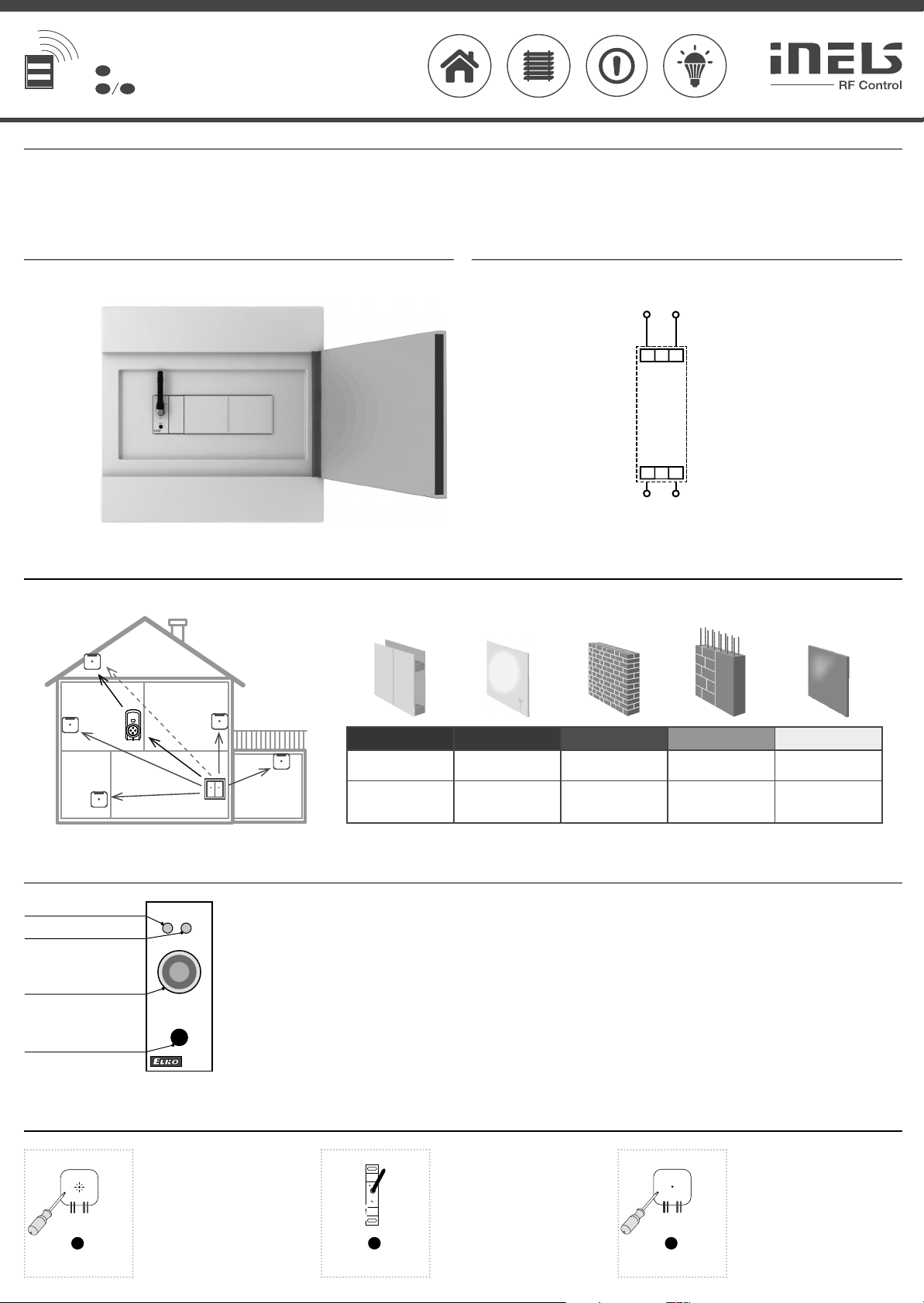
touch parts of the device that are energized – life threat. Due to transmissivity of RF signal, observe correct location
of RF components in a building where the installation is taking place. RF Control is designated only for mounting in
interiors. Devices are not designated for installation into exteriors and humid spaces. The must not be installed into
metal switchboards and into plastic switchboards with metal door – transmissivity of RF signal is then impossible. RF
Control is not recommended for pulleys etc. – radiofrequency signal can be shielded by an obstruction, interfered,
battery of the transceiver can get flat etc. and thus disable remote control.
Warning
Supply voltage:
Apparent input:
Dissipated power:
Supply voltage tolerance:
Power supply indication:
Input
Control voltage:
Control input power:
Control terminals:
The length of control impulse:
Transmission indication / function:
Transmitter frequency:
Signal transmission method:
Range in free space:
Minimum control distance:
Output for RF antenna:
Other data
Operating temperature:
Operating position:
Mounting:
Protection:
Overvoltage category:
Contamination degree:
Connecting conductor cross-
section (mm2):
Dimensions:
Weight:
Related standards:
* Max Tightening Torque for antenna connector is 0.56 Nm.
Attention:
When you instal iNELS RF Control system, you have to keep minimal distance 1 cm between
each units.
Between the individual commands must be an interval of at least 1s.
The company ELKO EP, as the manufacturer, is entitled to make technical modifications to the product, in the
technical specification and product manual, without prior notification.
ELKO
EP
,
s.r
.o.
|
Palackého
493
|
769
01
Holešov
,
Všetuly
|
Czech
Republic
|
e-mail:
[email protected]om
|
Support:
+420
778
427
36
6ELKO
EP
Germany
GmbH
|
Minoritenstr
.
7
|
50667
Köln
|
Deutschland
|
E-mail:
[email protected] |
T
el:
+49
(0)
221
222
837
80
ELKO EP Austria GmbH | Laurenzgasse 10/7 | 1050 Wien | Österreich | E-mail: elko@elkoep.at | Tel: +43 (0) 676 942 9314
www.elkoep.com / www.elkoep.de / www.elkoep.at
110-230V AC / 50-60 Hz
2VA
0.2W
+10 % / -25 %
green / grüne LED
AC 12-230V / DC 12-230V
AC 0.025VA / DC 0.1 W
S- S
min. 25ms (max. unlimited / max. unbegrenzt)
red / rote LED
866 MHz, 868 MHz, 916 MHz
unidirectionally addressed message /
eindirektional adressierte Nachricht
up to / bis zu 160 m
20 mm
SMA connector / Stecker SMA *
-15 ... + 50 °C
any / beliebig
DIN rail support / DIN-Schiene EN 60715
IP20 from the front panel / auf der Vorderseite
III.
2
max. 1x2.5, max. 2x1.5 / with a hollow / mit einem Leerstand
max.1x2.5
90 x 17.5 x 64 mm
62 g
EN 60669, EN 300220, EN 301489 R&TTE Directive, Order. No 426/2000
Coll. (Directive 1999/EC) /EN 60669, EN 300220, EN 301489 Richtlinie
RTTE, RG Nr.426/2000 Sgl. (Richtlinie 1999/EG)
Technische Parameters
Spannungsversorgung:
Scheinleistung:
Verlustleistung:
Toleranz Spannungsversorgung:
Spannungsversorgungsanzeige:
Eingang
Steuerungsspannung:
Steuerung Eingangsstrom:
Steuerungsanschlüsse:
Dauer des Steuerungsimpulses:
Übertragungsanzeige / funktion:
Sendefrequenz:
Signalübertragungsmethode:
Reichweite im Freien:
Minimale Distanz der Steuerung:
Ausgang für Antenne RF:
Weitere Daten
Arbeitstemperatur:
Arbeitsposition:
Installation:
Schutzart:
Kategorie Überspannung:
Verschmutzungsgrad:
Querschnitt der Verbindung
(mm2):
Abmessungen:
Gewicht:
Standards:
Die Betriebsanleitung dient der Montage, sowie dem Benutzer des Geräts. Sie ist immer im Lieferumfang enthalten.
Die Montage und der Anschluss darf nur durch eine Person mit einer angemessenen Berufsqualifikation, nach dieser
Bedienungsanleitung und Funktionen des Gerätes und unter Beachtung aller gültigen Vorschriften ausgeführt
werden. Die störungsfreie Funktion des Gerätes hängt auch von Transport, Lagerung und Handhabung ab. Falls Sie
irgendwelche Anzeichen von Beschädigung, Verformung, Fehlfunktionen oder Fehlteilen feststellen, ie das Gerät
nicht und wenden sich an den Verkäufer. Es ist notwendig, dieses Produkt und Teile davon als Elektronikschrott zu
behandeln, nachdem seine Lebensdauer beendet ist. Vor Beginn der Montage ist sicherzustellen, dass alle Leitungen,
miteinander verbundenen Teilen oder Anschlüsse spannungsfrei sind. Während der Montage und der Wartung
sind die Sicherheitsvorschriften, Normen, Richtlinien für die Arbeit mit elektrischen Geräten zu beachten. Berühren
Sie keine Teile des Gerätes, die mit Energie versorgt werden - Lebensgefahr. Aufgrund der Sendeleistung des RF-
Signals, beachten Sie den geeigneten Montageort der RF-Komponenten in einem Gebäude, in dem die Installation
stattfindet. RF Control ist nur für die Montage im Innenbereich geeignet. Geräte sind nicht für die Montage in
Außenbereichen und Feuchträumen geeignet. RF Control Komponenten dürfen nicht in Metallschalttafeln und in
Kunststoff -Schalttafeln mit Metalltür installiert werden - Die Durchlässigkeit des RF-Signals ist dann nicht gegeben.
RF Control ist nicht für Aufzüge geeignet - das RF Signal kann gestört und abgeschirmt werden, die Batterie des
Emfängers verliert schnell die Leistung etc. - dieses verhindert die Steuerung durch eine Steuerungseinheit.
Warnung
* Max. Anzugs-Drehmoment der Antennenverbindung ist 0.56 Nm.
Achtung:
Bei der Installation Aktoren iNELS RF Control muss es der Mindestabstand 1 cm geachtet sein.
Zwischen aufeinanderfolgenden Befehlseingaben sollte mindesten 1 s Abstand liegen.
Als Hersteller behält die Firma ELKO EP das Recht vor, technische Änderungen am Produkt, Änderungen der
technischen Spezifi kation und der Produktanleitung ohne vorherige Ankündigung vorzunehmen.