DEC MicroVAX 3100 40 Guide

MicroVAX3100
Model40andModel80
Troubleshooting and Diagnostic
Information
Order Number: EK-A0518-TM.001
October 1991
This manual describes the troubleshooting procedures and diagnostic
commands that you can use to solve basic problems with the MicroVAX
3100 Model 40 and Model 80 systems.
Revision Information: This is a new manual.
Digital Equipment Corporation
Maynard, Massachusetts

October 1991
The information in this document is subject to change without notice and should not be
construed as a commitment by Digital Equipment Corporation. Digital Equipment Corporation
assumes no responsibility for any errors that may appear in this document.
The software described in this document is furnished under a license and may be used or copied
only in accordance with the terms of such license.
No responsibility is assumed for the use or reliability of software on equipment that is not
supplied by Digital Equipment Corporation or its affiliated companies.
Restricted Rights: Use, duplication, or disclosure by the U.S. Government is subject to
restrictions as set forth in subparagraph (c)(1)(ii) of the Rights in Technical Data and Computer
Software clause at DFARS 252.227-7013.
© Digital Equipment Corporation 1991.
All Rights Reserved.
The postpaid Reader’s Comments forms at the end of this document request your critical
evaluation to assist in preparing future documentation.
The following are trademarks of Digital Equipment Corporation: Digital, MicroVAX, RX,
ThinWire, VAX, VAX DOCUMENT, VMS, and the DIGITAL logo.
This document was prepared using VAX DOCUMENT, Version 2.0.

Contents
Preface ..................................................... v
1 Troubleshooting and Diagnosing Problems
1.1 Troubleshooting . . . ................................... 1–1
1.1.1 Using the Troubleshooting Table . . . ................... 1–2
1.2 Diagnostic Tests and Commands ......................... 1–9
1.2.1 Power-Up Tests ................................... 1–10
1.2.2 Self-Tests ........................................ 1–12
1.2.3 Configuration Display . . . ........................... 1–14
1.2.4 System Exerciser .................................. 1–15
1.2.5 Summary Screens ................................. 1–18
1.2.6 Error Display . . ................................... 1–20
1.3 Contacting Digital Services . . ........................... 1–20
Index
Figures
1–1 Status LED Display ................................ 1–21
Tables
1–1 Basic Troubleshooting . . . ........................... 1–3
1–2 Device Numbers, Mnemonics, and Names ............... 1–13
iii

Preface
This manual describes the troubleshooting procedures and diagnostic
commands that you can use to solve basic problems with the MicroVAX™
3100 Model 40 and Model 80 systems.
Audience
This manual is intended for people who have some experience of computers.
Structure of This Manual
This manual has one chapter and an index.
Additional Information
See the MicroVAX 3100 Model 40 and Model 80 Operator Information manual
for the list of associated and related documents.
v

Conventions
The following conventions are used in this manual:
Convention Description
MONOSPACE
Text displayed on the screen is shown in monospace type.
italic type Italic type emphasizes important information and indicates the
complete titles of manuals.
boldface type Boldface type in examples indicates user input. Boldface type in text
indicates the first instance of terms defined either in the text, in the
glossary, or both.
Note A note contains information that is of special importance to the user.
vi

1
Troubleshooting and Diagnosing Problems
This chapter describes the troubleshooting procedures and diagnostic
commands that you can use to solve basic problems with the MicroVAX 3100
Model 40 and Model 80 systems. It contains information on the following:
• Troubleshooting
• Diagnostic tests and commands
• Contacting Digital™ Services
It also lists the information that you must give to your Digital Services
representative and where to find this information.
1.1 Troubleshooting
If a problem occurs, you must first make sure that all the cables, loopback
connectors, and terminators are correctly connected and that the connectors
are not damaged, for example, the pins may be broken or short-circuited.
Follow these steps:
1. Shut down the operating system following the procedures described in the
operating system documentation.
2. Turn off the console terminal and all the peripheral devices such as
printers and modems.
3. Turn off all the expansion boxes.
4. Turn off the system unit.
5. Check that the following cables, if installed, are correctly connected at both
ends and that the connectors are not damaged:
• Console terminal cable (linking the console terminal to the system unit)
• Console terminal power cord
• System unit power cord
• Expansion box SCSI cables
Troubleshooting and Diagnosing Problems 1–1

• Expansion box power cords
• ThinWire™ Ethernet cable or standard Ethernet cable
6. Check that the following terminators, if installed, are correctly connected
and are not damaged:
• SCSI terminator
• ThinWire Ethernet terminator (T-connector and two terminators)
• Standard Ethernet loopback connector
If you have correctly followed steps 1 to 5, the on/off switches on all
the components are set to the off (O) position, and you have solved any
problems caused by incorrectly connected cables or terminators.
7. Set the on/off switches on the following equipment to the on (|) position in
the following order:
a. Expansion boxes
b. Peripherals
c. Console terminal
d. System unit
The system responds with the power-up test display. If it does not, see
Section 1.1.1.
1.1.1 Using the Troubleshooting Table
Table 1–1 suggests the corrective actions for certain system problems. If you
have a problem with the system, follow these steps:
1. Write down the symptoms of the problem.
2. Check the Symptom column in Table 1–1 for a match.
3. Check the conditions for that symptom in the Possible Cause column. If
the column lists more than one possible cause, check the possible causes
and their suggested solutions in the order listed.
4. Follow the advice in the Suggested Solution column.
5. See Section 1.3 if the problem persists.
1–2 Troubleshooting and Diagnosing Problems

Table 1–1 Basic Troubleshooting
Symptom Possible Cause Suggested Solution
System Problems
The system unit fan is off
or the power light is off. The power cord is not
connected. The power cord
may be faulty. The power
socket may not be working.
Make sure that all the power cords
are connected correctly at both
ends. Try a power cord that works
or test the power socket with an
appliance that works.
The overload protection
circuitry of the power
supply may have shut down
because of an abnormal
condition on the power line.
Turn the system off and then turn
it back on.
The power supply unit
(PSU) is faulty. Contact your Digital Services
representative.
The power-up display does
not show after 20 seconds. The terminal cable is not
correctly connected. Make sure that all the cables are
connected at both ends.
The power cord is not
connected. The power cord
may be faulty. The power
socket may not be working.
Make sure that all the power cords
are connected correctly at both
ends. Try a power cord that works
or test the power socket with an
appliance that works.
The terminal fuse may have
blown. Replace the blown terminal fuse.
See the terminal documentation.
The terminal settings may
be incorrect. See the MicroVAX 3100 Model 40
and Model 80 Operator Information
manual for the list of correct
terminal settings. See the terminal
documentation for information on
setting up the terminal.
The port to which the
terminal connects may be
faulty.
Try connecting the terminal to
another system. If this solution
works, the port to which the
terminal was connected is faulty.
If the terminal still does not
operate, it is faulty. In either
case, contact your Digital Services
representative.
(continued on next page)
Troubleshooting and Diagnosing Problems 1–3

Table 1–1 (Cont.) Basic Troubleshooting
Symptom Possible Cause Suggested Solution
System Problems
The terminal cable may be
faulty. Connect the terminal cable and
the terminal to another system.
If the connected terminal works,
the DZ circuitry or MMJ connector
is faulty. Otherwise, the cable
is faulty. Contact your Digital
Services representative.
The break/enable switch is
in the wrong position. Turn off the system unit. Set the
break/enable switch to the down
position, then turn on the system
unit.
The power-up display
contains question marks. A soft error or hard error. A single question mark (?) followed
by numbers in the power-up display
indicates a soft error. Do not take
any action unless the system fails
to boot. If the system does not boot,
see Section 1.3.
Double question marks (??)
followed by numbers in the power-
up display indicate a hard error.
See Section 1.3.
The power-up test display
contains unexpected
characters.
The terminal settings are
incorrect or the DZ circuitry
is faulty.
Make sure the terminal settings
are correct, then run the power-
up test again. If the terminal is
set correctly, contact your Digital
Services representative.
The system fails to boot the
operating system. The system defaults are
incorrectly set. Set the system defaults as
described in the VMS Factory
Installed Software User Guide,
then try booting the system again.
If the system still fails to boot,
contact your Digital Services
representative.
(continued on next page)
1–4 Troubleshooting and Diagnosing Problems

Table 1–1 (Cont.) Basic Troubleshooting
Symptom Possible Cause Suggested Solution
RRD42 Compact Disc Drive Problems
The drive does not accept
the caddy. The disc is upside-down in
the caddy or it is not placed
correctly in the caddy.
Remove the disc from the caddy
and reinsert it properly.
The eject button fails to
eject the caddy. The eject button is disabled
by software. Reenable the eject button or
manually eject the caddy.
The system does not have
power. Set the system unit on/off switch to
the on (|) position and press the
eject button again.
(continued on next page)
Troubleshooting and Diagnosing Problems 1–5

Table 1–1 (Cont.) Basic Troubleshooting
Symptom Possible Cause Suggested Solution
TZ30 Tape Drive Problems
The TZ30 green LED
flashes rapidly. The drive mechanism is
faulty or the tape cartridge
is damaged.
Press and release the unload button
to clear the fault. If the LED
continues to flash, do not try to
remove the tape cartridge or use
the tape drive. Contact your Digital
Services representative.
The TZ30 does not operate. The drive does not contain
a tape cartridge. Insert the tape cartridge and press
the unload button.
The operate lever does not
slide. The tape cartridge is in use. Wait for the green LED to turn
on and try again. If the problem
persists, do not use the drive.
Contact your Digital Services
representative.
The operate lever does not
lock. The tape cartridge is not
inserted correctly. Reinsert the tape cartridge. If
the problem persists, contact your
Digital Services representative.
The tape does not load. Press and release the unload
button. Wait for the green LED
to turn on before sliding the lever
and removing the tape. If the
LED flashes, contact your Digital
Services representative.
The system cannot write to
the tape. The write-protect switch
is in the write-protect
position.
If the write-protect LED is on,
remove the tape, reset the switch
and try writing to the tape again. If
the problem persists, contact your
Digital Services representative.
The data read from the tape
cartridge is corrupted. The tape drive head may be
dirty. See the MicroVAX 3100 Model 40
and Model 80 Operator Information
manual for information on cleaning
the drive head.
The tape does not eject. The tape is not rewound.
The operate lever is in the
lock position.
Follow the procedure for removing
a tape from the TZ30 described in
the MicroVAX 3100 Model 40 and
Model 80 Operator Information
manual.
(continued on next page)
1–6 Troubleshooting and Diagnosing Problems

Table 1–1 (Cont.) Basic Troubleshooting
Symptom Possible Cause Suggested Solution
TZK10 Quarter Inch Cartridge (QIC) Tape Drive Problems
The data read from the QIC
tape is corrupted. The drive head is dirty. Clean the drive head. See the
MicroVAX 3100 Model 40 and
Model 80 Operator Information
manual.
The system cannot write to
the QIC tape. The write-protect switch
is in the write-protect
position.
Remove the QIC tape, reset the
switch and try writing to the QIC
tape again. If the problem persists,
contact your Digital Services
representative.
The system cannot read
from or write to the QIC
tape.
The QIC tape may be faulty. Remove the QIC tape. If the amber
LED turns off when you remove
the QIC tape, the tape is probably
faulty. Try a different QIC tape.
If the amber LED stays on or if
the problem persists, contact your
Digital Services representative.
(continued on next page)
Troubleshooting and Diagnosing Problems 1–7

Table 1–1 (Cont.) Basic Troubleshooting
Symptom Possible Cause Suggested Solution
RX™26 Diskette Drive Problems
The system cannot read
from or write to the
diskette.
The diskette is not
formatted. Format the diskette.
The diskette is not correctly
inserted. Eject the diskette. Try inserting
the diskette again.
The diskette is faulty. Try a different diskette.
The diskette drive is faulty. Contact your Digital Services
representative.
The diskette density is
incorrect. The RX26 accepts only high-
density (HD) or extra-density (ED)
diskettes.
The diskette drive head
may be dirty. See the MicroVAX 3100 Model 40
and Model 80 Operator Information
manual for information on cleaning
the diskette drive head.
The system can read
from but cannot write to
a diskette.
The write-protect switch
is in the write-protect
position.
Eject the diskette and reset the
switch. Try writing to the diskette
again.
The diskette does not eject. The diskette is incorrectly
positioned in the drive. Gently press the diskette with your
finger and reposition it. Press the
eject button again.
1–8 Troubleshooting and Diagnosing Problems

1.2 Diagnostic Tests and Commands
There are a number of diagnostic tests and commands that can help you to
isolate a problem with the system unit. These tests and commands are as
follows:
• Power-up tests
• Self-tests1
• Configuration display1
• System exerciser1
• Error display1
The following sections describe these tests and commands.
1You can use these tests and commands in privileged console mode only if the console
security feature is enabled and the password is set. See the MicroVAX 3100 Model 40
and Model 80 Customer Technical Information manual for information on the console
security feature.
Troubleshooting and Diagnosing Problems 1–9

1.2.1 Power-Up Tests
The system runs the power-up tests each time you turn on the system. If the
system passes the tests, it responds with a display similar to the following:
KA45−A V1.0
08−00−2B−1A−0B−BB
16MB
>>>
12
34
5
1Central Processing Unit (CPU) Name and Firmware Version Number—The
KA45 is the CPU in the Model 40 system; the KA47 is the CPU in the
Model 80 system. V1.0 is the firmware version number.
2Ethernet Hardware Address.
3Memory Size.
4Status Bar—The completion mark (|) indicates the full extent of the
status bar. When the status bar reaches the completion mark, the power-
up test is complete. On some terminals, the status bars are displayed as a
line of number signs (#).
5Console Prompt1.
1The system may not display the console prompt if the default recovery action is set to
boot or restart. See the MicroVAX 3100 Model 40 and Model 80 Customer Technical
Information manual for more information on system defaults.
1–10 Troubleshooting and Diagnosing Problems

If the power-up tests encounter an error, the system responds with a display
similar to the following:
08−00−2B−1A−0B−BB
16MB
>>>
?? 001 9 NI 0104
2345
1
|
6
KA45−A V1.0
1Error Type—Double question marks (??) indicate a hard error, that is, a
fatal error that prevents the system from booting. A single question mark
(?) indicates a soft error, that is, a nonfatal error that does not prevent the
system from booting.
2Field Replaceable Unit (FRU).
3Device Number.
4Device Mnemonic.
5Error Message.
6Completion Mark—The completion mark (|) indicates the full extent of
the status bar when the power-up test is successful.
In this display, a single question mark (?) indicates a soft error, whereas
double question marks (??) indicate a hard error.
Usually, you can ignore soft errors. Soft errors are often caused by temporary
problems, and the system can boot despite the error. Hard errors, however,
usually indicate a more serious problem that may prevent the system from
successfully booting. If you encounter a hard error, see Section 1.2.2.
Troubleshooting and Diagnosing Problems 1–11

1.2.2 Self-Tests
Self-tests perform the same tests as the power-up tests except for one
difference; the power-up tests test all the devices in the system, whereas
the self-tests allow you to test a single device.
If you encounter a hard error in the power-up test display, follow these steps:
1. Write down the number or mnemonic of the tests that failed.
In the examples in this section, device 9 (NI), the Ethernet device, has
a hard error associated with it. Table 1–2 lists the device numbers,
mnemonics, and names of the system devices.
2. Make sure that all the required cables and terminators are securely
connected to the proper ports by following the procedure described in
Section 1.1.
3. Run the self-test on each device that failed by entering a command similar
to the following:
>>> TEST 9
Alternatively, instead of the device number, you can enter the command
using the device mnemonic:
>>> TEST NI
If the self-test is successful, the system responds with the following display:
>>>
TEST 9
OK
>>>
1–12 Troubleshooting and Diagnosing Problems

If the device fails the self-test, the system responds with the following
display:
>>> TEST 9
?? 001 9 NI 0172
84 FAIL
>>>
4. If the error remains, contact your Digital Services representative (see
Section 1.3).
Table 1–2 lists all the device numbers, mnemonics, and device names.
Table 1–2 Device Numbers, Mnemonics, and Names
Number Mnemonic Device Name
1 NVR Nonvolatile RAM
3 DZ Serial line controller
4 CACHE Cache memory
5 MEM System internal memory
6 FPU Floating point unit
7 IT Interval timer
8 SYS Miscellaneous CPU module hardware
9 NI Network interface (Ethernet)
10 SCSI SCSI controller
12 COMM Synchronous communications option
14 ASYNC Asynchronous communications option
Troubleshooting and Diagnosing Problems 1–13

1.2.3 Configuration Display
The configuration display shows the system configuration and the error
messages that were detected while the most recent power-up tests and self-
tests were running. If you add expansion boxes to the system and do not run
the power-up tests or self-tests, the configuration display does not recognize the
reconfiguration. Enter the following command to see the configuration display:
>>> SHOW CONFIG
If the system does not detect any errors in the most recent power-up tests and
self-tests, it responds with a configuration display similar to the following:
KA45-A V1.0
08-00-2B-16-44-48
8MB
12 3
DEVNBR DEVNAM INFO
------ --------- -------------------------
1 NVR OK
3DZOK
4 CACHE OK
5 MEM OK
8MB = SY=8MB, S0/1=0MB, S2/3=0MB, S4/5=0MB
4
6 FPU OK
7ITOK
8 SYS OK
9NIOK
10 SCSI OK
3-RZ23L 6-INITR
5
12 COMM OK
DSW42 2 CHANNEL V3.0
14 ASYNC DHW41/2 V1.5
1Device Number Column.
2Device Mnemonic Column.
3Device Status Column.
4Memory Configuration—The total internal capacity of the system equals
the memory on the system module (SY) plus the optional memory in each
of the internal banks (S0 to S5). In this example, the capacity is 16M
bytes.
5SCSI IDs and SCSI Device Names.
1–14 Troubleshooting and Diagnosing Problems

If the system detects errors in the most recent power-up tests and self-tests, it
responds with a configuration display similar to the following:
KA45-A V1.0
08-00-2B-16-44-48
8MB
DEVNBR DEVNAM INFO
------ --------- -------------------------
1 NVR OK
3DZOK
4 CACHE OK
5 MEM OK
8MB = SY=8MB, S0/1=0MB, S2/3=0MB, S4/5=0MB
6 FPU OK
7ITOK
8 SYS OK
9 NI ?? 001 0104
1
10 SCSI OK
3-RZ23L 6-INITR
12 COMM OK
DSW42 2 CHANNEL V3.0
14 ASYNC DHW41/2 V1.5
1Error Information—Write down this information. You must give it to your
Digital Services representative when you call.
1.2.4 System Exerciser
Use the system exerciser if the system develops intermittent problems. The
system exerciser simulates the operating system by testing the simultaneous
operation of multiple devices in the system. The system runs the tests twice
and then shows the results in the system exerciser display.
Note
Remove the removable media from all the internal and external
removable media devices.
Troubleshooting and Diagnosing Problems 1–15
This manual suits for next models
1
Table of contents
Other DEC Desktop manuals

DEC
DEC Personal DECstation 5000 Manual
DEC
DEC 2000 Quick start guide
DEC
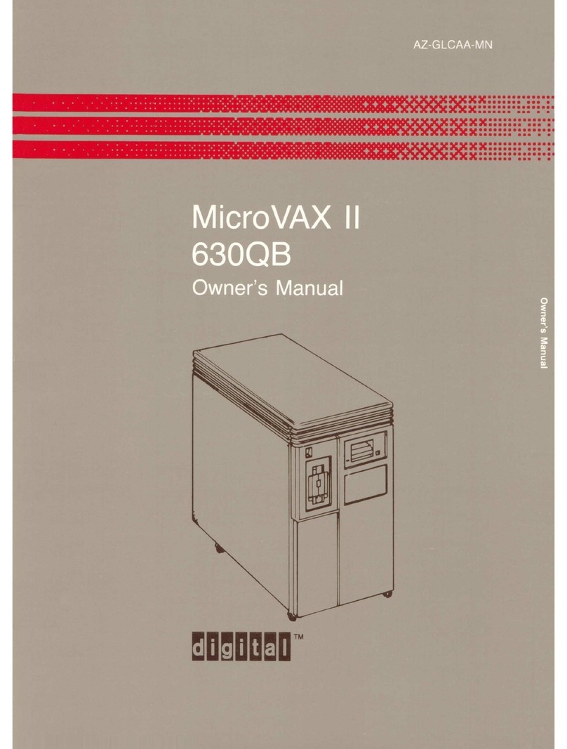
DEC MicroVax II 630QB User manual
DEC
DEC StorageWorks TZ8x7 Series Quick guide
DEC
DEC MicroVAX 3100 User manual

DEC
DEC DECpc 433 User manual
DEC
DEC Digital PC 3500 User guide
DEC
DEC MicroVAX 3100 85 Guide
DEC
DEC VAXstation 3100 User manual

DEC
DEC DECstation 316+ User manual

DEC
DEC Personal DECstation 5000 User manual

DEC
DEC DECstation 5000 Model 100 Series Manual

DEC
DEC VT125 User manual

DEC
DEC VT220 User manual
DEC
DEC 500 - Notebook PC User manual
DEC
DEC 3000 Model 600S User manual
DEC
DEC VT320 User manual

DEC
DEC DIGITAL PC 3010 User guide
DEC
DEC a-Series Assembly instructions
DEC
DEC 3000 800 User manual
