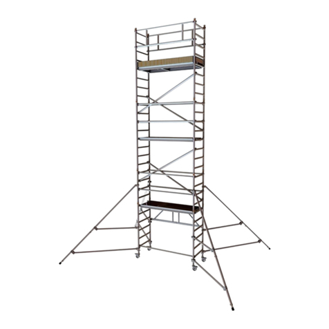
Note that TZ8x7-series tape drives are always physically installed in the upper
portion of the StorageWorks cabinet. Some host cable length is consumed by
the cable run from the first tape drive on the bus to the bottom of the cabinet.
This distance is approximately 2 meters for SW800 cabinets, and 1 meter for
SW500 cabinets. If your chosen host cable cannot reach from the tape drives to
the host taking the internal cable run into account, two DWZZA–AA SCSI signal
converters must be used to extend the bus. See the StorageWorks Family User’s
Guide for further information on using DWZZA–AA SCSI signal converters to
extend single-ended SCSI buses.
In the case where the host uses a differential SCSI bus, a DWZZA–AA SCSI
signal converter must be used to convert the differential bus to a single-ended
bus for use by the tape drives (refer to Figure 1–1). The signal converter should
be placed in or near the base of the StorageWorks cabinet to minimize the single-
ended bus length. The host cable must be long enough to reach from the first
tape drive on the bus to the signal converter at the base of the cabinet. (Note
that the host must operate in the 8-bit differential mode to function properly with
the DWZZA–AA SCSI signal converter.)
2.2.5 Installing the Tape Drives and Cabling
See the installation and user’s guide for your specific StorageWorks cabinet model
for detailed tape drive mechanical installation information. Using Figure 1–1 as
a guide, install adapter and jumper cables to interconnect the tape drives within
the cabinet. Install the terminator on the last tape drive on the bus.
You may use either connector on the rear panel to connect the tape drive to a
SCSI bus. The remaining connector may be used either to extend the bus to
additional devices or to terminate the bus with a H8574–A terminator.
Route the host cable from the bus’s first tape drive adapter cable to the base
of the cabinet using the guidelines in the cabinet’s installation and user guide.
Connect the cable to either the host or the signal converter, as appropriate.
2.2.6 Setting the Address Switch
Each tape drive has a SCSI bus address switch located on the rear panel next to
its bus connectors (refer to Figure 1–3). The address switch may be located on
either side of the connectors. The address switch on each tape drive must be set
to a different value to avoid bus conflicts.
Normally, TZ8x7-series tape drives are addressed in sequence, starting from
address 0 to address 3. Addresses 4 and 5 may also be used if desired, but
addresses 6 and 7 should be reserved for bus initiator use.
Using a pen or other small stylus, set the address switch on each tape drive.
See the installation and user’s guide for your specific TZ8x7-series tape drive for
detailed instructions on setting the address switch.
2.3 Planning and Installing Tape Drive Buses In Controller/Storage
Cabinets
The following sections describe the steps necessary to plan and install a
TZ8x7-series tape drive bus in a StorageWorks controller/storage cabinet.
Planning and Installing a TZ8x7-Series Tape Drive SCSI Bus 2–3


