DEC VAXstation 3100 User manual

EK-VSM40-OM-002
VAXstation
3100
Model
48
Owner's
Manual
digital
equipment
corporation
maynard,
massachuseits

July
19{K>
The
information
in
this
document
is
subject
to
change
without
notice
and
should
not
be
construed
as a commitanent by Digital
Equipment
Corporation.
Digital
Equipment
Corporation
assumes
no
responsibility
for
any
errors
that
may
appear
in
this
document.
Any
software
described
in
this
document
is
furnished
under
a
license
and
may
be
used
or
copied only
in
accordance
with
the
terms
of
such
license. No responsibility is
assumed
for
i^e
use
or reliability of software
or
equipment
that
is
not
supplied by Digital
Equipment
Cozporataon or
its
affiliated
companies.
Restricted
Rights:
Use,
duplication,
or
disclosure
by
the
U.S.
Giovemment
is
subject
to
restrictions
as
set
forth
in
siibparagraph
(c)(l)(ii) ofthe
Rights
in
'Technical
Data and
Computer
^ftware dause
at
DFARS
252.227-7013.
©
Digital
Equipment
Corporation
1990.
All
rights
reserved.
Printed
in
U.S.A.
The
postpaid
Reader's
Comments
forms
at
the
end
of
this
document
request
your
critical
evaluation
to
assist
in
preparing
future
docximentation.
The
following
are
trademarks
of
Digital
Equipment
Corporation:
CompacTape, DDIF,
DEC,
DECconnect,
DECnet,
DECUS,
DECwindows,
DELNI,
DEMPR,
Desktop-VMS,
DEMPR,
DESNC,
DSS, INTERNET,
LA75 Companion
Printer,
LN03, LN03R
ScriptPrinter,
MASSBUS,
PrintServer,
Q-bus,
ReGIS,
Remote
System
Manager,
RRD40,
ThinWire,
ULTRDC, UNEBUS, VAX, VAX DOCUMENT, VAXcluster, VAXpc,
VAXserver,
V^Xstation,
VMS,
VT,
XUI,
and
the
DIGITAL Logo
MS®, Microsoft®,
and
MS-DOS®
are
registered
trademarks
of
Microsoft
Coiporation.
NFS'"'
is
a
trademark
of
Sun
Microsystems,
Inc. IBM®
and
IBM
Personal
Computer
AT®
are
registered
trademarks
of
International
Business
Machines
Corporation.
Pos^cbipi® is a registered trademark
of
Adobe
Systems,
Inc. Teflon™
is
a
trademark
of
E.I.
Du
Pont
de
Nemoiirs
&Company,
Inc.
UNIX®
is
a
registered
trademark
of
American
Telephone
&
Telegraph
Company. X
Window
System®
is
a
trademark
of
the
Massachusetts
Institute
of
Tschnology.
FCC
NOTICE:
The
eqmpment
described
in
this
manual
generates,
uses,
and
may
emit
radio
frequency
energy.
The
equipment
has
been
type
tested
and
found
to comply
with
the
limits
for
a
Class
A
computing
device
pursuant
to
Subpart
J
of
Part
15
of
FCC
Rules,
which
are
designed
to
provide
reasonable
protection
against
such
radio
£requen<7
interference
when
operated
in
a
commercial
environment.
Operation
of
this
equipment
in
a
residential
area
may
cause
interference,
in
which
case
the
user
at
his
own
expense
may
be
required
to
take
measures
to
correct
the
interference.
S1396
This
document
was
prepared
with
VAX
DOCUMENT,
Version 1.2.

Contents
About
This
Guide
xi
1YourVAXstaNon
3100
System
1.1 System Highlights
1-2
1.2
The
VAXstation
3100
Family
1-3
2Installing
System
Hardwore
2.1 Choosing
the
Right Location
2-2
2.2 Unpacking
2-3
2.3 Setting Up Your System
2-4
2.3.1 Identifying System
Unit
Ports
and
Connectors
2-4
2.3.2 Connecting
the
Keyboard
2-6
2.3.3 Connecting
the
Mouse
2-7
2.3.4 Attaching
Ethernet
Tterminators
2-8
2.3.5 Connecting
the
Monitor
2-11
2.3.6 Connecting
the
Power
Cords
2-14
2.4 Connecting Optional or
E:^ansion
Hardware
2-16
2.5 Inserting Media 2-16
2.6
Starting
Your
System
2-17
2.6.1 Checking
the
Power-Up
Display
2-17
2.6.2
IfYou
Have
Problems
2-18
2.7
IfYou
Need
to
Set
the
Keyboard
Language
2-19
2.8 Connecting to a
Network
2-20
2.9
Getting
Ready
to
Install
Your
Operating
System
Software
2-20
2.10
Turning
Your
System
Off 2-21

3
Learning
About
Your
System
3.1
Hard
Disk
Drives
3-1
3.2
Using
the
RRD40 Compact Disc
Drive
3-2
3.2.1
Loading
a
Compact
Disc
3-2
3.2.2 Removing a
Compact
Disc
3-4
3.2.3
Inserting
the
Compact
Disc
into
the
Caddy
3-5
3.2.4 Removing
the
Compact Disc from
the
Caddy
3-7
3.2.5
Caring
for
Compact
Discs
3-8
3.3
Using
Tape
Cartridges
3-8
3.3.1 Labeling a
Tape
Cartridge
3-8
3.3.2
Writing
to
and
Protecting
Tape
Cartridges
3-9
3.3.2.1
Write
Protecting
a
Tape
3-10
3.3.2.2
Writing
to a
Tape
3-11
3.3.3
Handling
and
Storing
Tape
Cartridges
3-11
3.4
Using
the
TZ30
Tape
Drive
3-12
3.4.1
Inserting
a
Tape
Cartridge
3-12
3.4.2
Removing
a
Tape
Cartridge
3-14
3.4.3
Understanding
TZ30
Lights
3-15
3.4.4
If
You
Have
Problems
3-15
3.5
Mouse
3-15
4Adding
and
Using
Expansion Boxes ^
4.1
Guidelines
for
Connecting
Expansion
Boxes
4-2
4.2
Unpacking
an
Expansion
Box
4-4
4.3
Installing
a
Bottom
Dress
Cover
4-6
4.4
Preparing
Your
System
for
an
Expansion
Box
4-7
4.5
Connecting
One
Expansion
Box
4-9
4.6
Daisy-Chaining
Multiple
Expansion
Boxes
4-12
4.7
Adding
the
RRD40
Compact
Disc
Expansion
Box
4-14
4.7.1 Verifying
the
Voltage
Selector
Position
on
the
RRD40
4-15
4.7.2
Verifying
the
SCSI
ID
on
the
RRD40
4-15
4.7.3
Resetting
the
SCSI
ID on
the
RRD40
4-16
4.8
Adding
an
RZ55
Hard
Disk
Expansion
Box
4-16
4.8.1 Verifying
the
SCSI
ID
on
the
First
RZ55
4-17
4.8.2
Resetting
the
SCSI
ID
on
the
Second
RZ55
4-17
4.9
Adding
and
Using
a
IKSOZ-GA
Tape
Expansion
Box
4-19
4.9.1 Verifying
the
SCSI
ID
on
the
TK50Z-GA
4-19
4.9.2
Inserting
a
Tape
Cartridge
4-20
4.9.3
Removing
a
Tape
Cartridge
4-23
4.9.4
Using
TK50Z-GA
Controls
and
Indicator
Lights
4-24
Iv

5
Connecting
to
aNetwork
5.1 Connectingto a ThinWireEthernet Network 6-1
5.1.1
Verifying the Network Select Button Position
5-2
5.1.2 Verifying ThinTOre Ethernet Network Installation 5-3
5.1.3 Connecting ThinWire Ethernet Cable
5-5
5.1.4 Creating a Daisy-Chain WorkGroup 5-6
5.1.5 Connecting to a DECconnect Faceplate 5-7
5.1.6 Troubleshooting the ThinWire Ethernet Segment 5-8
5.2 Connectingto a Standard Ethernet Network 5-11
5.2.1
Setting the Network Select Button for Standard Ethernet
...
5-11
5.2.2 VerifyingYourStandard Ethernet Network Installation 5-11
5.2.3 TroubleshootingStandard Ethernet 5-12
5.2.4 Connecting a Transceiver Cable 5-14
5.2.5 Creating a Daisy-Chain Work Group 5-15
6
Troubleshooting
6.1
Identifying the Source ofa Problem 6-1
6.2 Using the Troubleshooting Table 6-3
7
Running
Diagnostics
7.1
Power-Up Messages 7-2
7.1.1
Power-Up Error Messages 7-3
7.1.2 Power-UpStatus Messages
7-4
7.2 Running Self-Ifests 7-5
7.3 ConfigurationDisplay 7-7
7.3.1 DZ
Status
Codes
7-9
7.4 Testing Internal Storage Devices 7-10
7.5 Testing
Memory
Modules 7-12
7.6 DeviceDisplay 7-15
7.7 Using the System Exerciser 7-17
7.8
Test
Utilities
7-19
7.8.1 RRD40
Tfest
Disc UtiHty 7-19
7.8.2 Erase Disk Utility for SCSI Hard Disks 7-20
7.9 Changing the KeyboardLanguage 7-22
7.10
Console
Commands
7-23
7.11
Password Security Feature 7-24
7.11.1
Enabling the Password Security Feature 7-26
7.12 Rebooting the System After Running Tests 7-28
7.13
Service
Information
7-29

8
Adding
Options
8.1
Printers
8-1
8.2
Modems
8-4
8.3
Tablet
8-6
8.4
Monitors
8-6
8.4.1 Long Monitor Cable Option
8-7
8.5 Graphics Coprocessor Module^Color Option
8-7
8.6
SPX
Color Graphics Accelerator
8-7
A
System
Parameters
A.l
Automatic
Booting
A-2
A.1.1
Setting
the
Default
Boot
Device
A-2
A.1.2 Changing
the
Default Recovery Action A-3
A.1.3
Setting
the
D^ault
Boot
Flags
A-5
A.2 Enabling
the
Server to Boot Satellite Systems Remotely A-5
A.3 Using an Alternate Console with YoiirSystem A-6
B
SCSI
IDs
B.l SCSI ID Default Settings B-1
B.2
Setting
the
SCSI ID B-3
B.3
Setting
SCSI
Switches
B-6
VI
Power-Up,
Seif-Test,
and
TEST
50
Status
and
Error
Codes
C.l
Monochrome
Video
Circuits
(MONO)
C-2
C.2
Time-of-Year Clock (CLK)
C-2
C.3
Nonvolatile
RAM (NVR)
C-3
C.4
Serial
Line
Controller
(DZ)
C-3
C.5
System
Memory
(MEM)
C-6
C.6 Memory
Management
(MM)
C-7
C.7
Floating
Point
(FP)
C-7
C.8
Interval
Timer
(IT)
C-7
C.9
SCSI
Bus
Controllers
(SCSI-A
and
SCSI-B)
C-8
C.l0
Interrupt
Controller
and
Ethernet
ID ROM (SYS)
C-15
C.ll
Graphics Coprocessor Module/Color Option
C-16
C.l2
Ethernet
Circuits
(NI)
C-17

D
Hardware
Specifications
E
Associated
Documents
Glossary
Index
Figures
1-1 VAXstation 3100 Model 48
System
1-1
2-1 Unpacking System Components 2-3
2-2
lifting
Equipment 2-4
2-3
Ports, Connectors,
and
Icons
2-5
2-4
Connecting the Keyboard to
the
System
Unit
2-6
2-5
Connecting
the
Mouse to
the
System
Unit
2-7
2-6
Connecting Terminators to the T-Connector
2-8
2-7 Connecting the T-Connector to
the
System
Unit
2-9
2-8 Connecting the Loopback Connector to the Sjrstem Unit 2-10
2-9
Connecting
the
Monitor Cable to
the
Monitor Using
the
Universal
Strain
Relief
Strap
2-12
2-10 Connecting
the
Monitor Cable to the System
Unit
2-13
2-11 Connecting
the
Monitor Power Cord 2-14
2-12 Connecting
the
Sjratem Power Cord 2-15
2-13 Opening
the
Front
of
the
Model 48 System
Unit
2-16
3-1 Opening
the
Front of the Model48 System Unit 3-2
3-2 Loading a Compact Disc 3-3
3-3 Compact Disc Caddy
3--5
3-4
Inserting Disc
in
Housing
3-6
3-5
Pressing Locking Tabs
3-7
3-6
Labeling a Tape Cartridge
3-9
3-7
Write Protecting aTape
3-10
3-8
TZ30 Lights
and
Controls 3-12
3-9
Inserting a Tape Cartridge in
the
TZ30 3-13
3-10
Removing a Tape Cartridge from
the
TZ30
3-14
4-1
50-Pin
Terminator
4-4
vll

4-2
Unpacking
an
RZ55 or
TK50Z-GA
Expansion
Box
4-5
4-3
Installing
Bottom
Dress
Cover
4-6
4-4
Removing
the
SCSI
Cover
4-7
4-5
Removing
the
SCSI
Terminator
4-8
4-6
Connecting
One
TK50Z-GA
or
One
RZ55
Expansion
Box
4-11
4-7
Connecting
One
RRD40
Expansion
Box
4-11
4-8
Connecting
IVo
Expansion
Boxes
4-13
4-9
RRD40
Compact
Disc
Expansion
Box
4-14
4-10
RRD40
Expansion
Box Voltage
Selector
and
Factory
SCSI
ID
Switch
Positions
4-15
4-11 Verifying
the
SCSI
ID on
the
First
RZ55
4-17
4-12
Resetting
the
SCSI
ID
on
the
Second
RZ55
4-19
4-13
Verifying
the
SCSI
ID on
the
TK50Z-GA
4-20
4-14
Inserting
and
Loading
a
Tape
in
the
TK50Z-GA
4-22
4-15
Removing
a
Tape
Cartridge
from
the
TK50Z-GA
4-23
5-1
Network
Select
Button
Set
for
ThinWre
Ethernet
5-3
5-2
Halt
Button
5-4
5-3
Adding
ThinWire
Cable
to a T-Connector
5-5
5-4
Checking
ThinWire
Cable
Connections
5-6
5-5
VAXstation
3100
Systems
in
a
Daisy-Chain
Work
Group
5-7
5-6
Connecting
to a
DECconnect
Faceplate
5-8
5-7
Removing
a
System
from
an
Active
ThinWlre
Segment
5-9
5-8
Connecting
a
Transceiver
Cable
to
the
System
Unit
5-14
5-9
Daisy-Chain
Work
Group
in
Standard
Ethernet
Environment
5-15
7-1
Halt
Button
7-6
7-2
Diagnostic
Lights
7-29
8-1
Connecting
a
Printer
Cable
to
tiie
System
Unit
8-2
8-2
Connecting aModem to
the
System
Unit
8-5
Tables
vin
3-1
Understanding
TZ30
Lights
3-15
4-1
Expansion
Box
SCSI
ID
Factory
Default
Switch
Positions
4-9
4-2
Using
the
TK50Z-GA
Controls
4-24
4-3
Understanding
TK50Z-GA
Lights
4-24
6-1
Troubleshooting
6-4
7-1 Device
Identifiers
in
Power-Up
and
Self-Tests
7-3
7-2
SCSI
Status
Codes
Indicating
Good Devices 7-11
7-3
SCSI
Status
Codes
Indicating
Possible
Problems
7-11

7-4 8-Digit Memory Error Code 7-14
7-5 SHOW DEVICE Display Column Heads 7-16
7-6 Error Messages for Erase Disk UtUity 7-22
7-7
SHOW
Commands
7-23
7-8
SET
Commands
7-23
7-9
Test
Commands
7-24
8-1 DeviceNames for Your Operating System 8-2
8-2
Printers
8~3
8-3
Modems
8-4
8-4
DeviceNames for Your Operating System 8-6
A-1
SCSI
Boot
Device
Names
..
A-2
A-2
Values for Default Recovery
A-4
B-1
SCSI
IDs
for
VAXstation
3100
Model
38
(with
Diskette
Drive) B-4
B-2
SCSI
IDs
for
VAXstation
3100
Model 38
(with
Hard
Disk) B-4
B-3
SCSI
IDs
for
VAXstation
3100
Model
48
B-5
B-4
RRD40
Expansion BoxSCSI IDs and Switch Positions B-6
B-5
RZ55/56
Expansion BoxSCSI IDs and Switch Positions B-6
B-6 TK50Z-GAExpansion BoxSCSI IDs and Switch Positions B-7
C-1
Monochrome
"^deo
Error
Codes
(OOOOJCXXX)
C-2
C-2
Time-of-Year Clock
Error
Codes
(OOOOJCXXX)
C-2
C-3
Nonvolatile
RAM
Error
Codes
(OOOOXXXX)
C-3
C-4
Serial
Line
Controller
Error
Codes (0000JXXXX)
C-3
C-5
Serial
line
Status
Codes
(OOOOWWWW)
C^
C-6
Keyboard
Self-Ttest
Codes
(YYYYYYYY)
C-5
C-7
Mouse
or
Tablet
Self-ltest Codes (ZZZZZZZZ)
C-5
C-8 System
Memory
Error
Codes
(OOOO.XXXX)
C-6
C-9
Memory
Management Error
Codes
(OOOO.OOOX)
C-7
C-10 Floating Point Error Codes
(OOOO.OOOX)
C-7
C-11 Binary Mask ofSelected Devices
(WWXX.OOOO)
C-8
C-12 Binary Mask of Error Flags
(OOOO.YYOO)
C-9
C-13
SCSI
Controller
Error
Codes
(OOOO.OOZZ)
C-9
C-14
Device
Status
Codes (DDMMSSTT)
C-12
C-15
Interrupt
Controller
and
Ethernet
ID ROM
Error
Codes
(OOOOJDCXX)
C-15
C-16 8-Plane Graphics ModuleError Codes
(OOOO.YYYO)
C-16
C-17
Ethernet
Circuits
Error
Codes
(OOOO.YYYY)
C-17
D-1
System Specifications
0-2
D-2 System Dimensions D-2
D-3 System Storage Conditions (Long-Term Storage) D-3
ix

D-4 Sjrstem Operating
and
Nonoperating Conditions
0-3
D-5 RZ23
Hard
Disk
Drive Specifications
D-4
D-6 RZ24
Hard
Disk Drive Specifications D-5
D-7
RZ55/RZ56
Hard
Disk
Drive
Dimensions
D-6
D-8 RZ55/RZ66
Hard
Disk Drive Specifications D-6
D-9 RZ55/RZ56
Hard
Disk Environmental Specifications D-7
D-10 TZ30 Tape Drive Specifications D-7
D-11 TK50Z-GA Tape Drive Specifications D-7
D-12 RRD40 Compact Disc Drive Specifications D-8
E-1
Associated
Documents
E-1

About
This
Guide
Purpose
of
This
Manual
This
manual
describes
how
to
install,
test,
and
maintain
the
hardware
components of a V^iXstation
3100
Model 48
computer
system.
Who
Should
Use
This
Manual
'"
\
This
manual
is
for
anyone
setting upand
using
the
Model
48
for
the
first
time.
It
includes
information
on
hardware
installation,
operation,
and
maintenance.
structure
of
This
Manual
This
manual
contains
eight
chapters,
five appendixes, aglossary
of
technical
terms,
and
an
index.
•Chapter 1includes
an
overview of
the
VAXstation 3100 Model
38
and
VAXstation
3100
Model 48
s3^tems,
and
introduces
you
to
the
product
features.
•
Chapter
2provides instructions for installing
your
new Model
48.
•
Chapter
3discusses
the
software
loading
devices (TZ30
tape
drive
and
RRD40 compact disc drive)
that
are
an
integral
part
of
your
system.
•
Chapter
4discusses
the
add-on storage
and
software loading
devices
that
can
be
used
with
your
system.
•
Chapter
5discusses connecting
your
system
to a simple
ThinWire
daisy-chain
work
group.
xl

•
Chapter
6provides basic s3rstem troubleshooting information.
•
Chapter
7describes how to
run
self-tests
and
system
diagnostics.
•
Chapter
8
lists
the
options
available
for
your
system.
It
also
shows
how
to
connect
a
printer
or
modem
to
your
system.
Appendixes provide
complementary
information
on
the
following
topics:
•
Appendix
A:
Customizing
your
startup
procedures
•
Appendix
B:
SCSI
ID
numbers
•
Appendix
C:
Status
and
error
codes
•
Appendix
D:
Hardware
specifications
•
Appendix
E:
Associated
documents
The
glossary
defines technical
terms
used
in
this
guide.
The
index
helps
you
to
find
the
information
you
need.
Guide
to
VAXstation
3100
Documentation
Manuals
The
manuals
you
will
use
to
install,
operate,
manage,
and
maintain
your
V^Xstation
3100
Model
48
system
are
listed
below.
The
left
column
lists
the
manuals;
the
light
column
contains
some
of
the
topics described
in
each
manual.
See
also Appendix E.
Topics
Planning
and
Preparation
Planning
workstation
placement
Checking power
requirements
Checking
environmental
reqtiirements
Connecting
a
monitor
Adjusting
brightness
and
contrast
Setting
up
the
system
unit
Connecting
the
keyboard
and
mouse
Turning
the
system
on
Connecting
to
a
network
Troubleshooting
and
diagnostic
testing
Adding
storage
devices
Monitor
Installation/Owner's
Guide
VAXstation
3100
Model
48
Owner's
Manual
xll

Workstations
Network
Guide
VMS
Installation
Guide
ULTRIX
Installation
Guide
VMS
DECwindows
User's
Guide
VWS
Installation
Guide
Desktop-VMS
Installation
Guide
Application
Installation
Guides
Defining
a
network
Describing
network
hardware
and
software
Setting
up
a
ThinWire
or
standard
Ethernet
network
Expanding
networks
Installing
VMS
operating
system
software
Backing
up
files
Installing
ULTRDC
system
sofi;ware
Backing
up
files
Using
DECwindows software,
an
optional
software
interface
layered
on
VMS
or
ULTRIX
Using
the
mouse
Manipulating
windows
Creating
and
xising files
Using
VWS software,
an
optional
software
interface
Installing
VWS
software
Backing
up
files
Using
Desktop-VMS software,
an
optional
software
interface
Installing
Desktop-VMS
software
Installing
and
using
applications
xill

Conventions
[ctFi/^
IReturn |
red
ink
bold
UPPERCASE
lowercase
Warning
Caution
Note
xlv
The
following
conventions
are
used
in
this
manual:
Asequence
such
as |Ctrl/x|
indicates
that
you
must
hold
down
the
key
labeled
Ctrl
while
you
press
another
key
or
a
pointing
device
button.
A
key
name
is
shown
enclosed
to
indicate
that
you
press
a
named
key
on
the
keyboard.
Red
ink
indicates
information
that
you
must
enter
from
the
keyboard.
In
the
online
version
of
the
book,
this
information
is
shown
in
bold
type.
Bold
type
is
used
to
introduce
new
terms.
New
terms
are
defined
in
the
Glossary.
Uppercase
letters
indicate
that
you
must
enter
a
command
exactly
as
shown.
For
example,
enter
SHOW.
Lowercase
letters
in
commands
indicate
that
you
must
provide
a
value.
For
example,
enter
SET
PASSWORD
new.password.
Warnings
contain
information
to
prevent
personal
injuay.
Read
these
carefully.
Cautions
provide
information
to
prevent
damage
to
equipment
or software.
Read
these
carefully.
Notes
provide
general
information
about
the
current
topic.

Margin
Icon
Definitions
o
<$-
Throughout
this
manual,
symbols
or
icons
in
the
margin
identify
important
switches,
buttons,
connectors,
or
procedures.
These
icons
are
briefly
described
here.
Figure
2-3
shows
the
locations
for
many
of
the
ports
and
switches.
Icons
That
Signal
Procedures
Certain
icons
act
as
reminders
about
important
procedures
that
are
being
described
in
the
nearby
text.
This
icon
signals
that
you
turn
to
another
guide
(for
instance,
the
monitor
guide)
for
more
complete
instructions
on a
certain
procedure.
Tlien
you
return
to
the
procedures
in
this
manu£d.
This
representation
of
an
on/off
switch
shows
the
off
(0) position.
This
icon
signals
that
you
should
turn
off
one
or
more
devices,
as
described
in
the
nearby
text.
The
on/off
switch
is
shown
in
the
on ( I ) position.
This
icon
signals
that
you
shovdd
turn
on
one
or
more
devices,
as
described
in
the
nearby
text.
Icons
for
Ports,
Connectors,
and
Buttons
This
section
describes
the
icons
that
appear
on
the
bezel
for
the
back
of
the
system
unit.
The
icon for a
port
or
connector
appears
in
the
margin
to
signal
that
you
connect
a
cable
to
that
port
or
connector.
The
icon
for
a
button
appears
to
signal
that
you
press
that
button.
See
Figure
2-3
for
icon
locations
on
the
bezel.
The
SCSI
icon
in
the
margin
signals
tiiat
you
attach
a
cable
or
terminator
to
the
SCSI
port.
The
icon
for
Ethernet
signals
a
procedure
with
one
of
the
Ethernet
connectors
or
the
network
select
button.
The
halt
icon
signals
that
you
press
the
halt
button
to
put
the
system
into
console
mode.
The
keyboard
icon
identifies
the
connector
where
you
put
the
keyboard
cable.
XV

^
The
mouse
icon
identifies
the
connector
where
you
putthe
mouse
[
(j^
cable
(or
the
tablet
cable).
©-
o
S3
h
xvl
This
icon
appears
on
the
cable for
the
mouse
(or
tablet). You
put
this
cable
into
the
port
with
the
mouse
icon.
The
monitor
icon
identifies
the
connector
where
you
put
the
monitor
cable.
The
printer
icon identifies
the
port for
the
printer
cable. This
port
also
supports
a
hardcopy
terminal
or
an
additional
video
terminal
for
alternate
console
mode.
See
Appendix
A.
The
communications
port
is
identified
by
this
icon. You
put
the
modem
cable
here,
if
you
have
this
option.
The
alternate
console
switch
is
identified
by
this
icon.
Appendix
A
gives
instructions
for
installing
and
using
an
alternate
console.
The
row
of
diagnostic
lights
on
the
back
of
the
system
imit
is
identified
bythis
icon.
Chapter
7
describes
how
touse
these
' ^
lights.

1
Your
VAXstation
3100
System
The
VAXstation
3100
Model
48
is
a
desktop
server/workstation
that
provides
the
full VMS or ULTRIX operating systems and
applications to diskless members of a work group. The VAXstation
3100
Model
48
also
functions
as
a
workstation
for
the
owner/local
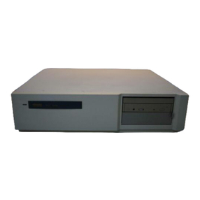
system manager. Figure
1-1
shows the VAXstation3100 Model 48
system.
Figure 1-1 VAXstation 3100 Model 48 System
MLO-002345
Your VAXstatton
3100
System
1-1

1.1
System
Highlights
The
Y&Xstation
3100
Model 48
and
the
Model
38
system
tmits
A
are
contained
in
similar
enclosures.
The
Model
48
enclosure
is
14.99
centimeters
(5.9
inches)
high;
the
Model 38
enclosure
is
smaller—10.3
centimeters
(4
inches)
high.
The
Model 48
system
unit
has
many
special
features,
as
described
in
the
following
list:
•RRD40
compact
disc drive—^The RRD40
compact
disc
drive
built
into
your
s3rstem
unit
is
a
read-only
optical disc device
that
stores
600 megabytes (or
about
200,000 pages) of
data.
Information is
read
from a compact disc (CD)
using
laser
technology, which
means
that
your
operating
system
software
can
be
installed
rapidly.
The
compact
disc
may
include
operating
system
software, windowing software, applications,
and
documentation.
• Memory—You
can
order
your
system
with
up
to 32 megabytes
of
memory.
• TZ30
tape
drive—^The built-in TZ30
tape
drive stores up to 95
megabytes
of
data
per
tape
cartridge.
•ThinWire
and
standard
Ethernet
connectivity—You
can
connect
to
either
standard
Ethernet
or
ThinWire
Ethernet
networks.
• RZ23
disk
storage—One to
three
RZ23 104-megab3rte
hard
disks
serve
as
your
system
disk
drive
and
as
storage for
the
diskless
users
in
the
work
group.
• RZ24
disk
storage—One to
three
RZ24 209-megabyte
hard
disks serve
as
your
system
disk
drive
and
as
storage for
the
diskless
users
in
the
work
group.
• Add-on storage—^The RZ55
hard
disk drive can be purchased
in
an
expansion
box
to
provide
you
with
an
extra
332
megab3rtes
of
storage.
• Add-on storage—^Different RZxx-xx
hard
disk
expansion box
options
are
available
to provide
you
with
a
variety
of
^tra
storage
configurations.
• Two
operating
systems
to choose from—VMS or
ULTRIX,
which
is Digital
Equipment
Corporation's
version
of
the
UNIX
operating
s3rstem.
Operating
system
software
is
purchased
separately
from
the
VAXstation
3100
hardware.
1-2
Your VAXstation
3100
System

•Windowing software—DECwindows software
and,
optionally,
VAX
Windowing
Software
(VWS/UIS), give
you
a
visual
way
to
organize
your
work
in
windows. You
can
run
several
different
applications
simultaneously
and
switch
between
them.
You
can
use
graphic
symbols
instead
of
command
lines
to do
your
work.
•
SCSI
connectivity—Small
Computer
System
Interface
(SCSI)
is
an
industry
standard
for
connecting
mass
storage
devices.
•
For
customers
requiring
additional
security
in
their
VAX
console,
you
can
secure
your
S3^tem
in
the
console
mode
using
the
password
security
feature.
See
Section
7.11 for
more
information
on
this
feature.
1.2
The
VAXstation
3100
Family
The
VAXstation
3100
systems
can
be
used
in
several
configurations, from a VAXstation 3100 Model 38 diskless
workstation
used
as
a
satellite
in
a
work
group,
to a
Model
38
standalone
workstation
with
hard
disks,
to
a
VAXstation
3100
Model
48
used
as
the
server
for
one
or
more
Model
38
workstations.
Your Model
48
system
can
be
used
as
a
standalone
workstation,
or
it
can
be
the
server
to
members
of
a
work
group.
It
can
be
a
networked
server
if
that
work
group is connected to a
larger
network.
The
Model
38
diskless
satellite
workstation
is
the
basic,
introductory
system.
It
provides
the
option
of
working
in
a
small
work
group
or
connecting
to a
network.
Your VAXstation
3100
System
1-3

2
Installing
System
Hardware
After helping you check
that
you have all your equipment,
and
the
right
location for your system, this chapter shows you how to
set
up
your
system, including:
• Ck}nnecting
the
keyboard
•
Connecting
the
mouse
•
Attaching
Ethernet
terminators
to
prepare
for
either
networking
or
diagnostic
tests
•
Connecting
the
monitor
•
Connecting
the
power
cords
•
Starting
your
sjrstem
The
chapter
then
guides you to getting your system up
and
running,
including:
•
What
to
do
if
you
are
planning
to connect to a
network
•
What
to do
if
you
are
planning
to
add
an
expansion
box,
modem,
or
printer
•
Where
to
learn
about
installing
your
operating
sjrstem
software
Installing System
Hardware
2-1
This manual suits for next models
1
Table of contents
Other DEC Desktop manuals

DEC
DEC DECpc LPx User manual
DEC
DEC 3000 500 User manual
DEC
DEC MicroVAX 3100 40 Guide
DEC
DEC MicroVax II 630QB User manual

DEC
DEC DECpc 433 User manual
DEC
DEC VAXmate User manual

DEC
DEC VT125 User manual
DEC
DEC 500 - Notebook PC User manual
DEC
DEC Digital PC 3500 User guide
DEC
DEC a-Series Assembly instructions

DEC
DEC DECstation 5000 Model 100 Series Manual

DEC
DEC DIGITAL PC 3010 User guide
DEC
DEC MicroVAX 3100 User manual
DEC
DEC 2000 Quick start guide
DEC
DEC StorageWorks TZ8x7 Series Quick guide
DEC
DEC VT320 User manual
DEC
DEC MicroVAX 3100 85 Guide

DEC
DEC DECstation 316+ User manual

DEC
DEC Personal DECstation 5000 User manual

DEC
DEC VT220 User manual
