Use and Care Guide
DAYLIGHT ADJUSTING INDOOR DIGITAL TIMER
4 HOMEDEPOT.com
Please contact 1-866-308-3976 for further assistance.
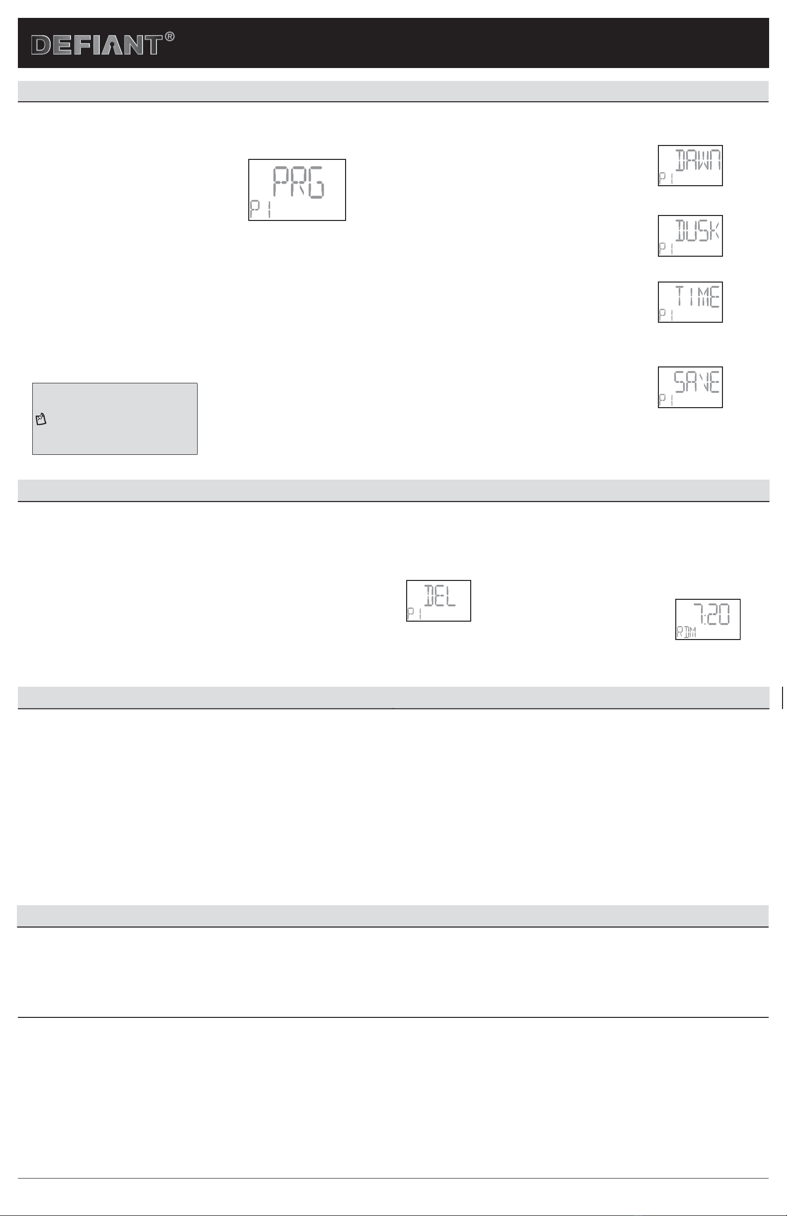
Programming
1 PROGRAMMING THE ON/OFF DAYS
a. Press SETUP twice to begin programming
ON/OFF days, and “P1 ON” will display.
b. Press ENTER once, and “SET” will display.
Press ENTER again to begin setting the
ON time, and “PRG” will be displayed with
the days of the week ashing. See Figure
13.
c. Press +or -to select the day(s) you want
this program to turn the timer ON:
□S, S (Saturday and Sunday)
□M, T, W, Th, F (weekdays only)
□S, M, T, W, Th, F, S (individual days)
□T, Th (Tuesday and Thursday)
□M, W, F (Monday, Wednesday, and
Friday)
□S, M, T, W, Th, F, S (default: all days of
the week)
d. Press ENTER to conrm the setting.
Proceed to the next step - PROGRAMMING
THE ON/OFF TIME.
Figure 13
SU
ON
MO TU WE TH FR SA
2 PROGRAMMING THE ON/OFF TIME
a. Press +and -to choose from one of these three
options to begin conguring the timer’s ON time.
Proceed to step b when you are nished setting
one of these three options:
□DAWN: This is the default screen. When you
reach this screen, press ENTER to set the timer’s
ON time to the DAWN time that is displayed. See
Figure 14.
□DUSK: When you reach this screen, press ENTER
to set the timer’s ON time to the DUSK time that
is displayed. See Figure 15.
□TIME: When you reach this screen, press ENTER
(see Figure 16). When the hour begins to ash,
press +or -to scroll to the desired hour, paying
attention to the AM/PM setting in the corner
of the display. Press ENTER when the hour is
correct. The minute will begin to ash on the
screen. Press +or -, followed by ENTER to set
the minute.
b. When “P1 OFF” and “PRG” display, follow steps 1c
through 2a to set the OFF days and times.
c. Once nished, “SAVE” will appear. See Figure 17.
Press ENTER to save this program, and “P2 ON”
will be displayed, with P2 ashing. If you need
additional programs, press ENTER and repeat steps
1c through 2b to set the next program ON/OFF
times. When you are nished programming ON/OFF
times, press AUTO to complete the programming.
Figure 14
SU
ON
MO TU WE TH FR SA
Figure 15
SU
ON
MO TU WE TH FR SA
Figure 16
SU
ON
MO TU WE TH FR SA
Figure 17
SU
ON
MO TU WE TH FR SA
Additional Programming Options
1 REVIEWING PROGRAMS
a. Press SETUP twice, followed by +or –to
scroll through the previously entered
programs.
b. Press AUTO when you are nished.
2 DELETING PROGRAMS
a. Press SETUP twice, followed by +
or -to scroll to the program you wish
to delete. Press ENTER and “SET” will
display.
b. Press +or -until the display shows
“DEL,” then press ENTER. See Figure
18.
c. The program is now deleted, and you
may press +or -to select another
program for deletion following the
steps above. Press AUTO when you
have completed deleting all desired
programs.
Figure 18
SU
ON
MO TU WE TH FR SA
3 SETTING THE RANDOM (RND)
SECURITY OPTION
The random feature will turn the lights ON
and OFF using the programmed times “+”
or “-” 30 minutes, giving the house a more
lived-in appearance while the occupant is
away.
a. Push RND to activate the random
feature. The screen will change
from “AUTO” to “RDM”.
See Figure 19.
b. Push AUTO to de-activate the
random feature and return the
timer to its current programming.
Figure 19
OFF
AM
MO
Additional Features
USING THE MANUAL OVERRIDE FEATURE (OPTIONAL)
To manually override the timer and turn the lights off and on at your convenience, there are two
options:
1. Manual override with active programming: Press the timer door or the ON/OFF button,
which will turn the lights on and off. In this option, your programs will still be active and
the override will only last until the next scheduled program.
2. Manual override with inactive programming: Following these steps will inactivate the
programing. In this setting, you must press the ON/OFF button or the timer door for the
lights to turn on and off.
a. Press and hold + and – at the same time until you see “MAN” display on the
screen.
b. Now your timer will work like a manual switch, just press on the timer door or the
ON/OFF button to turn the lights on and off at your convenience.
c. To return your timer to AUTO mode (where your programs are activated), press and
hold + and – at the same time and the timer will go back into AUTO mode.
COUNTDOWN MODE
• Press and hold the On/Off button for about 2 seconds.
• Display will show 10, 20, 30, 40, 50 min., 1 HR, 1.5 HR, 2 HR, 3 HR.
• Release button when desired countdown time is displayed.
• Timer will stay on for this time and then return to previous mode.
FCC NOTE
This device complies with part 15 of the FCC and Industry Canada license-exempt RSS standard(s). Operation is subject to the following two conditions: (1) this device may not cause harmful interference, and (2) this device must accept any
interference received, including interference that may cause undesired operation.
FCC NOTE: The manufacturer is not responsible for any radio or TV interference caused by unauthorized modications to this equipment. Such modications could void the user’s authority to operate the equipment.
NOTE: This equipment has been tested and found to comply with the limits for aClass B digital device, pursuant to Part 15 of the FCC Rules. These limits are designed to provide reasonable protection against harmful interference in aresidential
installation. This equipment generates, uses and can radiate radio frequency energy and, if not installed and used in accordance with theinstructions may cause harmful interference to radio communications. However, there is no guarantee that
interference will not occur in a particular installation.If this equipment does cause harmful interference to radio or television reception, which can be determined by turning the equipment off and on, the user isencouraged to try to correct the
interference by one or more of the following measures:
-- Reorient or relocate the receiving antenna.
-- Increase the separation between the equipment and receiver.
-- Connect the equipment into an outlet on a circuit differentfrom that to which the receiver is connected.
Consult the dealer or an experienced radio/TV technician for help
CAN ICES-3(B)/NMB-3(B)
NOTE: Programs will not work if they overlap.
NOTE: You can add up to 7 programs.
NOTE: The timer screen will return to the clock
if no buttons are pushed for 1 minute.
Item #469-637
Model #49814
UPC #043180498144
Troubleshooting
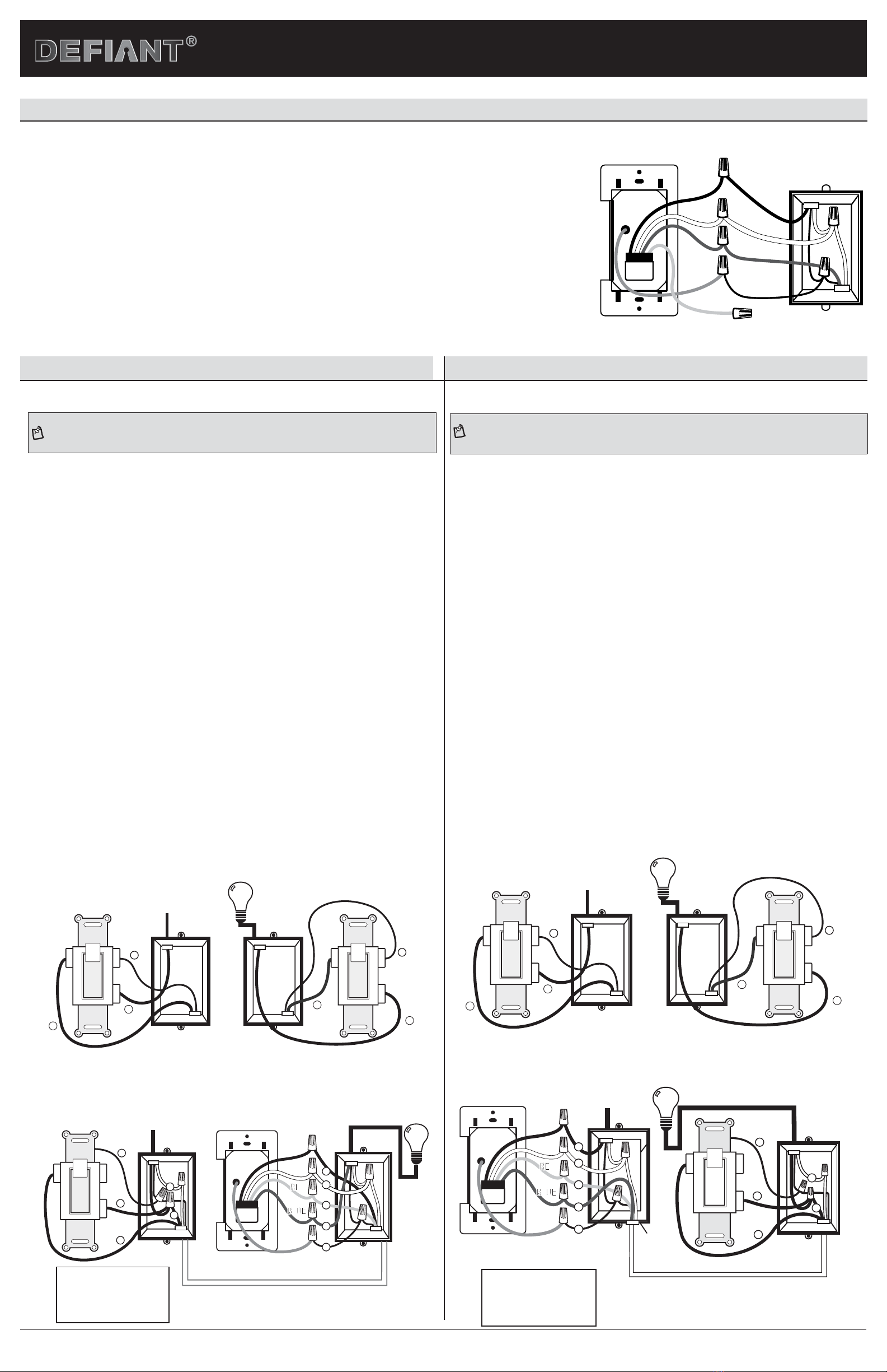
Three way switch will not work:
• Make sure jumper wiring is correct.
Lights on all day controlled by timer:
• Check to make sure the clock time is set for correct am/pm
• Check to make sure Dusk time and dawn time are not reversed
Lights come on and off at times different than they programmed:
• Check to see if there are multiple programs on the timer that conict with each other.
• 3-Way switch may have been used to turn lights off or on, the timer should function correctly during the next program cycle.