manuals.online logo
Brands
  1. Home
  2. •
  3. Brands
  4. •
  5. Defiant
  6. •
  7. Timer
  8. •
  9. Defiant 24780 User manual

Defiant 24780 User manual

Use and Care Guide
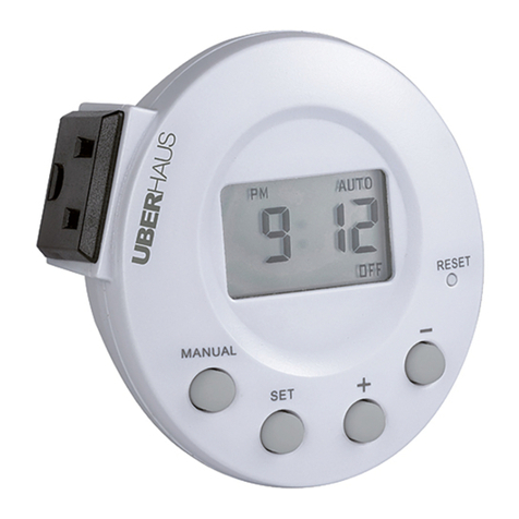
In-Wall App Timer
IP07232014 HOMEDEPOT.com
Please contact 1-866-308-3976 for further assistance.
Item #1001-470-469
Model #24780
UPC #030878247801
Before You Begin
Product Information
□For use only with permanently installed xtures
□For use with single pole or 3-way wiring congurations
□Compatible with all incandescent and CFL/LED bulbs
□Screw Terminal Installation - Requires wiring connections for Line (Hot), Load, Neutral,
Ground, and Traveler (Traveler is only used in 3-way congurations)
Safety Information
WARNING
RISK OF ELECTRIC SHOCK:
Shut off the power at the fuse box or circuit breaker before installation
All wiring connections must be made with the power OFF to avoid personal injury and/or
damage to the switch
Do not use in wet locations
Use indoors only
RISK OF ELECTRIC FIRE:
Exercise extreme caution when using this device to control appliances. Operation of these
devices may automatically be powered on due to timed event programming. Depending
upon the appliance, these unattended or unintentional operations could possibly result in
a hazardous condition. For these reasons, do not use this device to control electric heaters
or any other appliances which may present a hazardous condition due to unattended or
unintentional or automatic power on control.
Do not use to control appliances that contain heating elements (cooking appliances,
heaters, irons, etc.).
Do not exceed electrical ratings.
Use copper wire only with this device.
Do not use to control receptacles.
WARNING: This device is intended for installation in accordance with the National Electric Code and
local regulations in the United States, or the Canadian Electrical Code and local regulations in Canada.
if you are unsure or uncomfortable about performing this installation, consult a qualied electrician.
WARNING: Do not use with medical or life support equipment. Never use this device to supply power
to, or control the On/Off status of medical and/or life support equipment.
WARNING: Do not disassemble this product. There are no serviceable parts inside.
Product Specications
□For indoor use only.
POWER MAX LOADS
120VAC, 60Hz 1800W (15A) Resistive;
960W (8A) Tungsten
1/4 HP
Hardware Included
AA - Screw x2 BB - Jumper Cable x2 CC - White & Light Almond Faceplate
Suggested Tools
Phillips screwdriver Wire strippers
Warranty
The manufacturer warrants this product to be free from manufacturing defects for a period of one year
from the original date of consumer purchase. This warranty is limited to the repair or replacement of this
product only and does not extend to consequential or incidental damage to other products that may be used
with this product. This warranty is in lieu of all other warranties, expressed or implied. Some states do not
allow limitations on how long an implied warranty lasts or permit the exclusion or limitation of incidental
or consequential damage, so the above limitations may not apply to you. This warranty gives you specic
rights, and you may also have other rights which vary from state to state.
Contact Home Depot customer service at 1-866-308-3976 or visit www.homedepot.com for more information.
Pre-Installation
CHANGING THE FACEPLATE
This device includes a light-almond faceplate. To switch faceplates, follow the steps below.
a. Gently remove the white faceplate by squeezing the sides of the white faceplate and pulling
away from the timer. Starting at the top and working your way downwards until it pops off.
b. Find the light-almond faceplate in the package. Place the new faceplate into position and
carefully push until it snaps into place.
Installation Terms and Options
WARNING: Shut off power at the fuse box or circuit breaker before performing any wiring or installation.
BASIC WIRING TERMINOLOGY
To better familiarize yourself with the wiring terminology and concepts referenced in this manual, please review the following information before you begin wiring this timer to your switch outlet.
If at any time during the wiring process you become uncertain, please contact a certified electrician.
□Line: This is the 120V AC (hot) from breaker box.
□Load: This is the 120V AC wire that controls the xture (load out) which carries power to the light.
□Neutral: 120V AC return connection.
□Ground: 120V AC safety ground.
□Traveler-1 and Traveler-2: Wires running between two 3-way switches for installations where a light is controlled by two switches.
INSTALLATION OPTIONS
To begin the installation process, you must rst know what type of installation is needed. Below are the 3 different installation options. Please refer to the following descriptions for the
installation instructions that apply to you.
1. Single-Pole Installation (Complete steps 1-3 and 6 in the Installation section):
This installation option should be used when a switch only controls one light from a single location. A typical example of where you would nd a single-pole switch is your bedroom or
bathroom light switch.
2. 3-Way Installation, Load Side (Complete steps 1-2, 4, and 6 in the Installation section):
This installation option replaces a switch which controls a light that can be controlled from two locations and in most installations has the common (hot) terminal tied to the lamp/load the
switch turns OFF and ON. Typically these types of installations are in stairwells, hallways, and large rooms with multiple accesses points.
3. 3-Way Installation, Line Side (Complete steps 1-2, 5, and 6 in the Installation section):
This installation option replaces a switch which controls a light that can be controlled from two locations and in most installations has the common (hot) terminal tied to 120VAC. Typically
these types of installations are in stairwells, hallways, and large rooms with multiple accesses points.
Installation
1 REMOVING THE OLD SWITCH
a. Shut off power to the circuit at the circuit breaker or fuse box.
b. Remove the existing wall plate.
c. Carefully remove the existing switch from the switch box. DO NOT disconnect the wires. OR
2 IDENTIFYING THE TERMINALS ON THE APP TIMER
a. Identify the terminals on the new switch as this diagram shows:
1
4
5
3
2
□1 – Ground (Green/Bare)
□2 – Load (Black)
□3 – Line (Black)
□4 – Traveler (Red/Other)
□5 – Neutral (White)
b. Disconnect the wires from the existing switch. Label the wires (ground, load, line, traveler,
neutral).
Use and Care Guide
In-Wall App Timer
IP07232014 HOMEDEPOT.com
Please contact 1-866-308-3976 for further assistance.
Installation (continued)
3 SINGLE-POLE INSTALLATION - CONNECTING THE WIRES TO THE NEW SWITCH
IMPORTANT: This switch is rated for and intended for use only with copper wire.
Use 14AWG or larger wires suitable for at least 80°C for supplying Line (HOT), Load, Neutral,
and Ground.
a. Strip the wire length according to the following parameters:
□For attachment using the enclosure’s holes, strip insulation 5/8 in. (16 mm)
NOTE: UL species that the tightening torque for the screws is 14 Kgf-cm (12 lbf-in). Refer to the diagram
on the left which demonstrates the proper insertion and tightening of the wires into the terminals on the
switch.
b. Connect the green or bare copper ground wire to the GROUND terminal (1).
c. Connect the black wire that goes to the xture to the LOAD terminal (2).
d. Connect the black wire that comes from the electrical service panel (Hot) to the LINE
terminal (3).
Out to Light (Load)
3
5
2Load
Ground
Neutral
Line
1
From Breaker Box
e. Connect the white wire to the NEUTRAL terminal (5) (use included jumper wire if needed). Often the neutral (white) wire can be found in the back of the wire box connected with a wire nut.
There may be several neutral wires bound together. Connect the jumper wire (supplied part BB) to all neutral wires bound together making sure the wire nut is tight. Connect the jumper
wire to the NEUTRAL terminal (5).
4 LOAD SIDE 3-WAY INSTALLATION INSTRUCTION
NOTE: The common is typically a dark colored screw on a single pole or 3-way toggle switch.
NOTE: If you are using your timer to control a uorescent lamp, the timer must be installed on a load-side
wiring box.
PREPARING THE SWITCH ON THE LINE SIDE
a. Disconnect the power from the circuit by turning off the circuit breaker or removing the
fuse from the fuse box.
b. Using the Line Side diagram shown below as a reference, label and remove the line wire
(1) from the common terminal and the Traveler-2 wire (7).
c. Connect the jumper wire (supplied part BB), the line wire (1) from the common terminal C,
and the Traveler-2 wire (7) together. You should have three wires connected with one wire
nut.
d. Connect the other end of jumper (6) back to the common terminal (C) on the switch.
Consider recording the marking/color coding of the Traveler-1 (5) and Traveler-2 (7) wires
so you can tell them apart for later use.
e. Tuck the wires into the box, leaving room for the switch.
f. Install the switch back into the box and install wall plate.
INSTALLING THE TIMER ON THE LOAD SIDE
a. Using Load Side diagram as a visual guide, remove the load side 3-way switch and the
three wires, labeling the wire on the common terminal as Load (4) and the traveler wires.
b. Connect the removed LOAD wire (4) to the LOAD terminal (2) on the timer.
c. Using Timer on the Load Side as a visual reference for the remaining steps, connect the
Traveler-2 wire (7) to the LINE terminal (3) on the timer.
d. Connect the Traveler-1 (5) wire to the TRAVELER terminal (4) on the timer.
e. Connect the white neutral wire (2) from the switch box to the NEUTRAL terminal (5) of the
timer (use included white jumper wire if needed). Often the neutral (white) wire can be
found in the back of the wire box connected with a wire nut. There may be several neutral
wires bound together. Connect the jumper wire (supplied part BB) to all neutral wires
bound together making sure the wire nut is tight. Connect the white jumper wire to the
NEUTRAL terminal (5).
f. Connect the ground wire (3) in the switch box to the GROUND terminal (1) on the timer.
g. Tuck the wires into the switch box, leaving room for the timer.
h. Use the supplied screws to install the timer, being careful not to crush or pinch the wires
and install wall plate.
i. Restore power at the circuit breaker or fuse box.
j. If the light xture does not operate properly, disconnect the power at the circuit breaker or
fuse box. Then swap the wires connected to the line terminal (3) and traveler terminal (4)
on the timer.
k. Verify that the light xture turns ON and OFF when you manually turn the timer ON and
OFF. Perform this test with the remote switch in both positions. You should hear the timer
relay click ON/OFF. If you hear the relay click but the light xture does not turn ON/OFF
properly, check your wiring.
5 LINE SIDE 3-WAY INSTALLATION INSTRUCTION
NOTE: The common is typically a dark colored screw on a single pole or 3-way toggle switch.
NOTE: If you are using your timer to control a uorescent lamp, the timer must be installed on a load-side
wiring box.
PREPARING THE SWITCH ON THE LOAD SIDE
a. Disconnect the power from the circuit by turning off the circuit breaker or removing the
fuse from the fuse box.
b. Using the Load Side diagram shown below as a reference, label and remove the load
wire
(4) from the common terminal and the Traveler-2 wire (7).
c. Connect the jumper wire (supplied part BB), the load wire (4) from the common terminal
C, and the Traveler-2 wire (7) together. You should have three wires connected with one
wire nut.
d. Connect the other end of jumper (6) back to the common terminal (C) on the switch.
Consider recording the marking/color coding of the Traveler-1 (5) and Traveler-2 (7) wires
so you can tell them apart for later use.
e. Tuck the wires into the box, leaving room for the switch.
f. Install the switch back into the box and install wall plate.
INSTALLING THE TIMER ON THE LINE SIDE
a. Using Line Side diagram as a visual guide, remove the line side 3-way switch and wires,
and label the wire removed from the common terminal (C).
b. Using Timer on Line Side as a visual guide, connect the line wire (1) to the LINE terminal
(3) on the timer.
c. Connect the white netural wire (2) from the switch box to the NETURAL terminal (5) on the
timer. Often the neutral (white) wire can be found in the back of the wire box connected
with a wire nut. There may be several neutral wires bound together. Connect the white
jumper wire (supplied part BB) to all neutral wires bound together making sure the wire
nut is tight. Connect the white jumper wire to the NEUTRAL terminal (5).
d. Connect the traveler-1 wire (5) to the TRAVELER terminal (4) on the timer and the
traveler-2 wire (7) to the LOAD terminal (2) on the timer. Connect the ground wire (3)
(green or bare wire in box) to the GROUND terminal (1) on the timer.
e. Carefully tuck the wires into the switch box, leaving room for the timer.
f. Use the supplied screws to install the timer, being careful not to crush or pinch the wires.
g. Restore power at the circuit breaker or fuse box and install wall plate.
h. Verify that the load turns ON and OFF when you manually turn the timer ON and OFF.
Perform this test with the remote switch in both positions.
i. If the load does not operate properly, disconnect the power at the circuit breaker or fuse
box. Then swap the wires connected to the load terminal (2) and traveler terminal (4). This
can be done on the timer.
Typical Wiring Schematic
for 3-Way Installation
2
7
5
65
7
4
GROUND
C
HH
Typical Wiring Digram for 3-way installation
with timer on load side
Load
Line
5
1
7
Hot Side
Line
LINE SIDE
SWITCH ON LINE SIDE
LOAD SIDE
TIMER ON LOAD SIDE
C
HH
5
4
7
C
HH
Connecting the Timer Wires for a
3-Way Installation - Timer on Load Side
2
Load
1 = Line
2 = Neutral
3 = Ground
4 = Load
5 = Traveler 1
6 = Jumper
7 = Traveler 2
C = Common
terminal
In a typical 3-way application there are two 3-way switches. The switch on the “HOT”
side has the common terminal tied to 120VAC. The switch on the “LOAD” side has the
common tied to the lamp/load the switches turn OFF and ON.
3
1
3
Typical Wiring Digram for 3-way installation
with timer on line side
Connecting the Timer Wires for a 3-Way
Installation - Timer on Line Side
1 = Line
2 = Neutral
3 = Ground
4 = Load
5 = Traveler 1
6 = Jumper
7 = Traveler 2
C = Common
terminal
2
7
GROUN
SWITCH ON LOAD SIDE
DLoad
C
HH
4
5
6
3
Typical Wiring Schematic
for 3-Way Installation
5
1
7
Hot Side
Line
LINE SIDE LOAD SIDE
C
HH
5
4
7
C
HH
Load
In a typical 3-way application there are two 3-way switches. The switch on the “HOT”
side has the common terminal tied to 120VAC. The switch on the “LOAD” side has the
common tied to the lamp/load the switches turn OFF and ON.
5
7
1
Line
TIMER ON LINE SIDE
2
3
Use and Care Guide
In-Wall App Timer
IP07232014 HOMEDEPOT.com
Please contact 1-866-308-3976 for further assistance.
Installation (continued)
6 INSTALLING THE SWITCH
a. Insert the switch into the switch box and be careful not to pinch or crush the wires.
b. Secure the switch to the box using the supplied screws.
c. Mount the wall plate.
d. Restore power to the circuit at the fuse box or circuit breaker and test the system.
e. Timer LED should be ashing.
Operation
1 DOWNLOADING THE DEFIANT APP
□Go to your Apple or Android smartphone App Store and download the free DEFIANT TIMER app.
2 USING THE APP
This gure shows the main screen of the DEFIANT timer app with the following menu options.
1. on/off – This menu option overrides the current timer programming to turn the connected device on/
off. The timer will follow the next scheduled programmed time.
2. dusk to dawn – This menu option programs your timer to turn on at dusk and off at dawn daily.
3. random – This menu option uses the programmed time to turn on/off randomly to give a “lived in”
look while away.
4. program – This menu option sets up to 5 programs to turn your connected device on/off.
5. countdown – This menu option turns your connected device on for up to 24 hours. The timer will
return to the next programmed time afterwards.
6. clear – This menu option restores your timer and app to default settings or clears the timer of all
programs.
7. Daylight saving – Slide to turn the Daylight Saving time feature on or off depending on if your area
observes daylight saving time.
8. Info screen – All screens on the DEFIANT app have an information page for additional information and
directions on using each menu option in the app.
program
clear
dusk to dawn
random
on / off
countdown
Daylight saving
1 2
8
4
6
7
3
5
3 PROGRAMMING THE APP TIMER
□Connect the provided 3.5 mm jack to the smart switch and your smartphone or tablet. Gently remove
the rubber guard from the 3.5mm jack.
□Launch the DEFIANT app on your smartphone or tablet and follow the on-screen guide to add, control,
and program schedules.
□Remove the jack when you are nished programming the app timer.
TIMER LED TIMER STATUS
Rapid Flashing LED Timer is not programmed. This is the default status.
Always ON Timer is being programmed by the DEFIANT TIMER APP.
Always OFF Timer is programmed and will run your on/off programs.
4 MANUAL OPERATION
□To manually operate your switch, press the top of the switch to turn the xture ON. Press the bottom of
the switch to turn the xture to Standby/OFF.
□If you wired your App Timer in a 3-way application, you may also use your 3-way switch to override the
current App Timer programming. The App Timer will follow the next scheduled ON or OFF time.
ON
OFF
FCC NOTE
This device complies with part 15 of the FCC and Industry Canada license-exempt RSS standard(s). Operation is subject to the following two conditions: (1) this device may not cause harmful
interference, and (2) this device must accept any interference received, including interference that may cause undesired operation.
FCC NOTE: The manufacturer is not responsible for any radio or TV interference caused by unauthorized modications to this equipment. Such modications could void the user’s authority to
operate the equipment.
NOTE: This equipment has been tested and found to comply with the limits for aClass B digital device, pursuant to Part 15 of the FCC Rules. These limits are designed to provide reasonable
protection against harmful interference in aresidential installation. This equipment generates, uses and can radiate radio frequency energy and, if not installed and used in accordance with
theinstructions may cause harmful interference to radio communications. However, there is no guarantee that interference will not occur in a particular installation.If this equipment does cause
harmful interference to radio or television reception, which can be determined by turning the equipment off and on, the user isencouraged to try to correct the interference by one or more of the
following measures:
-- Reorient or relocate the receiving antenna.
-- Increase the separation between the equipment and receiver.
-- Connect the equipment into an outlet on a circuit differentfrom that to which the receiver is connected.
Consult the dealer or an experienced radio/TV technician for help
CAN ICES-3(B)/NMB-3(B)

This manual suits for next models

1

Other Defiant Timer manuals

Defiant 1000-003-074 User manual

Defiant

Defiant 1000-003-074 User manual

Defiant 31072 User manual

Defiant

Defiant 31072 User manual

Defiant 49815 User manual

Defiant

Defiant 49815 User manual

Defiant 469-637 User manual

Defiant

Defiant 469-637 User manual

Defiant 49808 User manual

Defiant

Defiant 49808 User manual

Defiant 1000-003-074 User manual

Defiant

Defiant 1000-003-074 User manual

Defiant TM-087 User manual

Defiant

Defiant TM-087 User manual

Defiant TM-074 User manual

Defiant

Defiant TM-074 User manual

Defiant 544-068 User manual

Defiant

Defiant 544-068 User manual

Defiant 32648 User manual

Defiant

Defiant 32648 User manual

Defiant 29068 User manual

Defiant

Defiant 29068 User manual

Defiant 49814 User manual

Defiant

Defiant 49814 User manual

Defiant 469-637 User manual

Defiant

Defiant 469-637 User manual

Defiant 13257 User manual

Defiant

Defiant 13257 User manual

Popular Timer manuals by other brands

Leviton TS300 installation instructions

Leviton

Leviton TS300 installation instructions

ALGE-Timing TDC8001 manual

ALGE-Timing

ALGE-Timing TDC8001 manual

NSi INDUSTRIES Tork RZ327 Programming instructions

NSi INDUSTRIES

NSi INDUSTRIES Tork RZ327 Programming instructions

ETI 806-150 operating instructions

ETI

ETI 806-150 operating instructions

Emos P5526 manual

Emos

Emos P5526 manual

Pixsys TCT101-1ABC user manual

Pixsys

Pixsys TCT101-1ABC user manual

CEI-Ultrak ULTRAK 485 operating instructions

CEI-Ultrak

CEI-Ultrak ULTRAK 485 operating instructions

Anslut 006044 operating instructions

Anslut

Anslut 006044 operating instructions

GE SunSmart 15312 Programming instructions

GE

GE SunSmart 15312 Programming instructions

Tork DZS200 Installation & operation

Tork

Tork DZS200 Installation & operation

GAO 552446 operating instructions

GAO

GAO 552446 operating instructions

Oh!FX TC-109 Quick user guide

Oh!FX

Oh!FX TC-109 Quick user guide

Intermatic EJ341C instructions

Intermatic

Intermatic EJ341C instructions

Perry Electric 1IO 6081 instruction manual

Perry Electric

Perry Electric 1IO 6081 instruction manual

Wistar T202 instruction manual

Wistar

Wistar T202 instruction manual

Fluke PM 6666 Operator's manual

Fluke

Fluke PM 6666 Operator's manual

Clas Ohlson 31-4165 quick start guide

Clas Ohlson

Clas Ohlson 31-4165 quick start guide

Becker Centronic TimeControl TC42 operating instructions

Becker

Becker Centronic TimeControl TC42 operating instructions

manuals.online logo
manuals.online logoBrands
  • About & Mission
  • Contact us
  • Privacy Policy
  • Terms and Conditions

Copyright 2025 Manuals.Online. All Rights Reserved.