INSTALLATION
• Mixer: Supplywith cold water and hot water at 70°C maximum (we recommend 45°C to avoid
the risk of scalding).
• Pressure: 1 - 5 bar (100 - 500kPa), we recommend 3 bar (300kPa).
Maximum pressure differential at the inlets: 1 bar.
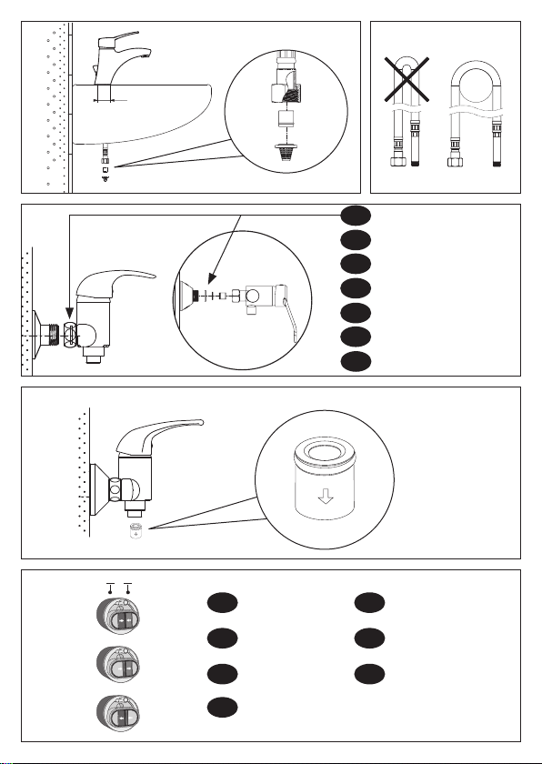
• Take care not to pinch the flexibles (Fig. B).
REMEMBER
• Our mixers must be installed by professional installers in accordance with current regulations
and recommendations in your country, and the specifications of the fluid engineer.
• Sizing the pipes correctly will avoid problems of flow rate, pressure loss and water hammer
(see calculation table in our brochure and online at www.delabie.com).
• Protect the installation with filters, water hammer absorbers and pressure reducers to reduce
the frequency of maintenance (recommended pressure from 1 to 5 bar maximum).
• Install stopcocks close to the mixer/tap/valve to facilitate maintenance.
• The pipework, filters, non-return valves, stopcocks, bib taps, cartridge and all sanitary fittings should
be checked at least once ayear, and more frequently if necessary.
INSTALLING THE MIXERS
• Deck-mounted, single hole washbasin or sink mixers (Fig. A):
- Mount the mixer body on the washbasin or sink (drill hole Ø34mm) and tighten the two nuts
on the threaded rods.
- Connect using F⅜" PEX flexibles*.
- Ensure a suitable waterproof seal between the mixer and the work plan appropriate to the type
of installation.
• All pressure-balancing (EP) mixers must be fitted with the filters supplied to protect the non-return
valves from impurities (Fig. A & B).
Note: If the cold water supply fails, the pressure-balancing cartridge known as "EP" reduces the flow
of hot water at the outlet.
• Wall-mounted mixers for sinks and showers (Fig. C):
The space between the water inlets is rarelyidentical to that ofthe mixer centres (150mm ±20).
The off-set connectors supplied deal with this issue.
• Mixers with standard connectors:
1. Using FTPE tape or waterproof sealant on the ½" threaded connector, tighten the off-set connectors
at right angles to the wall.
2. Mount the conical cover plates and adjust connectors to fit, ensuring that the mixer is horizontal.
Tighten the cover plates onto the offset connectors by hand.
3. Insert the waterproof washers into the valve nuts and tighten the mixer using a spanner.
• Mixers supplied with STOP/PURGE or STOP/CHECK connectors:
See the installation guide supplied with the 2 connectors (ref. 847327.2P, 855027.2P or 855755.2P
and 855755UK.2P).
* For coppertails or 15mm compressionfitting options please contact Technical Support.
EN