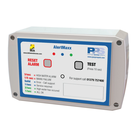
Delta AlertMaxx DMS-270 Manual

AlertMaxx
Installation & Operating Instructions
For Ground Water (DMS - 270) and Foul Water (DMS - 269)
T. 01992 523532
W. www.deltamembranes.com
Pump Station High Level Alarm

AlertMaxx

AlertMaxx
For technical support, please call 01279 757400 3
Contents
1.0 AlertMaxx overview 4
2.0 Box contents 4
2.1 Cardboard box contents 4
2.2 AlertMaxx unit contents 4
3.0 Technical information 5
4.0 Unit location 5
5.0 Mounting instructions 5
5.1 Mounting the AlertMaxx unit 5
6.0 Connecting mains power to the AlertMaxx unit 6
7.0 Installing the oat switch in the chamber 7
7.1 Installing a nger oat into a ground or surface water chamber 7
7.2 Installing a pendant oat into a foul water chamber 7
8.0 Connecting the oat switch to the AlertMaxx unit 9
9.0 Activating & testing the AlertMaxx unit 11
9.1 Turning on the AlertMaxx unit for the rst time 11
9.2 Testing the oat switch 11
9.3 Finalising the settings 11
10.0 Connecting external devices 12
11.0 Servicing 13
12.0 Spares 13
13.0 LED Codes 14
14.0 Troubleshooting 14

1.0 AlertMaxx overview
This high level alarm is designed to alert home owners when the water level in their pump chamber becomes
too high. The unit will also inform home owners when a service is due on their pump station.
2.0 Box contents
4 For technical support, please call 01279 757400
AlertMaxx
Groundwater version (DMS-270)
• 1 x Finger Float Switch
• 1 x Finger Float Housing
• 2 x Cable Ties
Foul Water version (DMS-269)
• 1 x Pendant Float Switch
• 1 x Cable Tie
2.1 Cardboard box contents
• 2 x Large Cable Gland
• 2 x Large Blanking Plug
• 2 x Small Cable Gland
• 2 x Small Blanking Plug
• 1 x 6V Battery
2.2 AlertMaxx unit contents
• 1 x AlertMaxx Unit
• 1 x Installation & Operating Instructions

AlertMaxx
For technical support, please call 01279 757400 5
3.0 Technical information
AlertMaxx Specication
Size (without cable glands) W: 115mm x D: 95mm x H: 60mm
Weight 650g
Mains Supply 200-250V AC (50Hz)
Internal Battery Pb 6V - 1.2Ah
Alarm Sound Level 81db
Visual Display Red, Blue, Green LED
4.0 Unit location
The AlertMaxx must be positioned in an area where the alarm can be clearly heard and is permanently
accessible.
5.0 Mounting instructions
5.1 Mounting the AlertMaxx unit
1. Usingthetemplateprovidedonpage15ofthisinstructionmanual(gure1),markthexing
positions on the wall.
2. Drillthetwoholesandtsuitablewallplugs(ensurecorrectwallplugsareusedforthewalltype).
3. Remove the screws from the front of the unit that secure the front fascia.
4. Secure the AlertMaxx unit to the wall using appropriate screws.
CAUTION! - When securing the unit to the wall, avoid over tightening the screws as this may
cause the box to crack.
PLEASE NOTE - The AlertMaxx unit is not waterproof and must be installed indoors or
inside a kiosk.

6.0 Connecting mains power to the AlertMaxx unit
6 For technical support, please call 01279 757400
AlertMaxx
1. Replace the far right blanking plug (large) with a large cable gland.
2. Feed the mains power cable through the right hand cable gland (large) and connect the power cable
totheterminalstrip(seegure2).
CAUTION! - Ensure mains power is isolated before connecting it to the AlertMaxx unit and seek
advice from a qualied electrician.
Figure 2. Connecting mains
BLUE
BLACK
ENL
40
120
20
70
50
80
7.0 Installing the oat switch in the chamber
Caremustbetakentoensurethecorrecttypeofoatswitchisinstalledintothechamber.Figures3&4
showthetwooatswitchoptions.
7.1 Installing a nger oat into a ground or surface water chamber
1. Usingthenutandwasherprovided,securethengeroattotheinsideoftheoathousingsothatthe
oatriseswithrisingwaterlevels(seegure5).
2. Usingthetwocabletiesprovided,attachtheoathousingtothedischargearmsoitis300mmfromthe
baseofthechamber(seegure6).

AlertMaxx
For technical support, please call 01279 757400 7
7.0 Installing the oat switch in the chamber
PLEASE NOTE - The pendant oat switch should be located in a position where the oat can
pivot with rising water levels and not become obstructed (see gure 8).
Figure3.Fingeroatswitch Figure4.Pendantoat
7.2 Installing a pendant oat into a foul water chamber
Option 1 - Free standing foul pump
1. Usingthecabletieprovided,attachtheoatcabletothedischargearmallowingthebottomoftheoat
switchtohangapproximately350mmabovethebaseofthechamber(seegure7).
Suitable for ground & surface water Suitable for foul water
BROWN
BLACK
ENL
40
120
20
70
50
80
BROWN
BLACK
ENL
40
120
20
70
50
80
Option 2 - Guide rail mounted foul pump
1. Pulltheoatcablethroughtheoatweight.
2. Usingacabletie,securetheoatweighttotheoatcablesothereis80mmofoatcablebetweenthe
topoftheoatswitchandthebottomoftheoatweight.
3. Drillaholethroughtheoatbracket.Hangthependantoatfromtheoatbracketsothebottomofthe
oatswitchhangsapproximately400mmfromthebaseofthechamber.Oncethependantoatisatthe
correctheight,securetheoatcabletotheoatbracketusingacabletie.

7.0 Installing the oat switch in the chamber
8 For technical support, please call 01279 757400
AlertMaxx
Figure 6. Ground Water Sump (DMS - 164)Figure 5. Ground Water Float Switch
Figure 7. Foul Water Sump (DMS - 165)Figure 8. Foul Water Float Switch
300mm
BROWN
BLACK
ENL
40
120
20
70
50
80
BROWN
BLACK
ENL
40
120
20
70
50
80

AlertMaxx
For technical support, please call 01279 757400 9
8.0 Connecting the oat switch to the AlertMaxx unit
Figure9.Wiringangeroatswitch
BROWN
BLACK
ENL
40
120
20
70
50
80
1. Usingadrawcord,pulltheoatcablethroughthecableduct.
2. PulltheoatcablethroughthecableglandontheAlertMaxxunit.Whenusingthengerswitch
(gure3),usethesmallcablegland.Whenusingthependantoatswitch(gure4),usethelarge
cable gland.
3. Connecttheoatswitchcabletotheterminalstrip.Whenusingthengeroat(gure3),connectthe
blueandabrowncable,(seegure9).Whenusingthependantoatswitch(gure4),connecttheblue
andblackcabletothealarmbox(seegure10).TheBROWNcableshouldbedisregardedandisolated.
PLEASE NOTE - If the cable supplied with the oat switch is too short, the cable can be extended
using a cable with a minimum core cross sectional area of 1mm².

8.0 Connecting the oat switch to the AlertMaxx unit
10 For technical support, please call 01279 757400
AlertMaxx
Figure10.Wiringapendantoatswitch
BLUE
BLACK
ENL
40
120
20
70
50
80

AlertMaxx
For technical support, please call 01279 757400 11
9.0 Activating & testing the AlertMaxx unit
Beforegoingthroughthetestingprocess,ensurethemainspowertotheAlertMaxxunitisswitchedo.
9.1 Turning on the AlertMaxx unit for the rst time
1. Remove the battery from the AlertMaxx unit and connect the red and black leads to the battery, red to
red and black to black.
2. Re-secure the battery to the unit by pressing the Velcro on the battery hard against the Velcro on the unit
until a ‘click’ is heard.
3. Oncethebatteryhasbeenconnected,thealarmwillbeepthreetimesandallthreeLEDswillash
three times.
4. CheckthatthegreenLEDasheseverysecondandafteroneminutetheunitemitsashortbeep
followedbyaashfromtheredLEDevery5seconds.
5. TurnonthemainspowersupplytotheAlertMaxxunit.Thebeepandredashfromstep4willstopafter
approximately 30 seconds.
9.2 Testing the oat switch
1. Test the alarm by pressing and holding the ‘TEST’ button for ten seconds. The alarm will sound and the
redLEDwillasheverysecond.
2. Releasethe‘TEST’button.ThealarmandashfromtheredLEDwillstopwithin10seconds.
3. Testtheoatswitchbyraisingtheoatswitchtoitsuprightposition.Thealarmwillactivatewithin
10 seconds.
9.3 Finalising the settings
1. Press the ‘RESET’ button to reset the unit.
2. The activation & testing is now complete and the AlertMaxx unit is ready for use.

10.0 Connecting external devices
12 For technical support, please call 01279 757400
AlertMaxx
Figure 11. Installing an external device
The AlertMaxx unit has volt free contacts to connect external devices such as an alarm or beacon. When the
alarm is activated the relay sends a signal once every second.
The volt free relay is designed to accept devices with a maximum load of 0.5A and voltage between +6 to
7V DC. If external devices fall outside these parameters, the external device must be powered by an external
power supply.
Figure 11 below shows the volt free terminal connections.

AlertMaxx
For technical support, please call 01279 757400 13
11.0 Servicing
The AlertMaxx unit will alert home owners when their pump station requires servicing. This is indicated by
theblueLEDashingeverysecondfollowedbyonebeepeveryminute.Thebeepcanbemutedbypressing
the ‘RESET’ button. However, the beep will return 7 days from pressing the ‘RESET’ button until a service
technician resets the alarm unit.
The AlertMaxx unit has a factory default service interval of 12 months.
12.0 Spares
DMS - 194
Float Switch type BR10 for foul water applications
DMS - 276
Brokenngeroatswitchforgroundandsurfacewaterapplications
DMS - 277
Shroudforbrokenngeroatswitch
DMS - 275
Rechargeable 6v battery
BROWN
BLACK
ENL
40
120
20
70
50
80
BROWN
BLACK
ENL
40
120
20
70
50
80

13.0 LED codes
14 For technical support, please call 01279 757400
AlertMaxx
Beep Red LED Blue LED Green LED Fault
1/sec None
1/sec 3/sec High water level
3/sec High water level but has been reset
2/sec High water level has occurred
1/min 1/5sec 1/sec Nomainspower
1/min 1/sec 1/sec Pump station service required
On 1/sec Float or cabling error
Low/atbattery
Allashinsequence Batterytooattostartup
1/sec Various Various Internal errors
14.0 Troubleshooting
Fault Cause
The unit does not turn on Batteryisat-chargethebatterybyconnecting
mains supply to alarm unit
Still doesn’t turn on after 3 mins - alarm unit is
faulty
TheLEDsashinthefollowingorder,red,blue,
green
Low battery - charge the battery by connecting
mains supply to alarm unit
The red LED is on continuously and the blue LED
asheseverysecond
Floatswitchcableisfaulty-checkoatswitch
connections and cable for damage
Floatswitchisbroken-replaceoatswitch
Floatcableisbroken-replaceoatswitch
Thealarmdoesnotactivatewhentheoatswitch
is lifted
The alarm does not activate when pressing the
‘TEST’ button.
Faulty unit
Alarm continuously active Pendantoathasbeenincorrectlywired-check
the blue and black cables are connected correctly

AlertMaxx
For technical support, please call 01279 757400 15
Figure 1. (Scale 1:1) Mounting hole positions
Top
Bottom

T. 01992 523532
W. www.deltamembranes.com
DeltaHouse,MerlinWay,NorthWeald,Epping,EssexCM166HR
After Sales Service
AllDeltaMembranePumpSystemsarettedandcanbemaintainedbyourpartnersPackagedPump
Systems.Withourlong-termrelationshipweensurethatthesystemselectedistforyourrequirements,
isdeliveredontime,professionallyttedandoershasslefreeon-goingoperationandmaintenance.
PPS - Precise, Passionate Service
Precise
Fully trained in-house service engineers to maintain, enhance and replace equipment.
Passionate
Bespokedesign,manufacturingandinstallationensuringourequipmentistforeveryrequirement.
Service
Fromttingtoscheduledmaintenancetheyensureyourneedscomerst.
• Fully stocked vans
• Emergency breakdown service
• Out of hours service
• Planned maintenance
• Factory trained engineers
T. 01279 757400
W. www.ppsgroupuk.com
This manual suits for next models
1
Table of contents
Other Delta Security System manuals