DFI ADS101 User manual

ADS101_ADS103
Thin Mini-ITX Industrial Motherboard
User’s Manual
© January 29, 2024 DFI Inc.

2
User's Manual | ADS101_ADS103
Copyright
This publication contains information that is protected by copyright. No part of it may be repro-
duced in any form or by any means or used to make any transformation/adaptation without the
prior written permission from the copyright holders.
This publication is provided for informational purposes only. The manufacturer makes no
representations or warranties with respect to the contents or use of this manual and specifi-
cally disclaims any express or implied warranties of merchantability or fitness for any particular
purpose. The user will assume the entire risk of the use or the results of the use of this docu-
ment. Further, the manufacturer reserves the right to revise this publication and make changes
to its contents at any time, without obligation to notify any person or entity of such revisions or
changes.
Changes after the publication’s first release will be based on the product’s revision. The website
will always provide the most updated information.
© 2024. All Rights Reserved.
Trademarks
Product names or trademarks appearing in this manual are for identification purpose only and
are the properties of the respective owners.
FCC and DOC Statement on Class B
This equipment has been tested and found to comply with the limits for a Class B digital
device, pursuant to Part 15 of the FCC rules. These limits are designed to provide reason-
able protection against harmful interference when the equipment is operated in a residential
installation. This equipment generates, uses and can radiate radio frequency energy and, if not
installed and used in accordance with the instruction manual, may cause harmful interference
to radio communications. However, there is no guarantee that interference will not occur in a
particular installation. If this equipment does cause harmful interference to radio or television
reception, which can be determined by turning the equipment off and on, the user is encour-
aged to try to correct the interference by one or more of the following measures:
• Reorient or relocate the receiving antenna.
• Increase the separation between the equipment and the receiver.
• Connect the equipment into an outlet on a circuit different from that to which the re-
ceiver is connected.
• Consult the dealer or an experienced radio TV technician for help.
Notice:
1. The changes or modifications not expressly approved by the party responsible for com-
pliance could void the user’s authority to operate the equipment.
2. Shielded interface cables must be used in order to comply with the emission limits.

3
User's Manual | ADS101_ADS103
Table of Contents
Chapter 1 - Introduction................................................................................................................6
Specifications.........................................................................................................................6
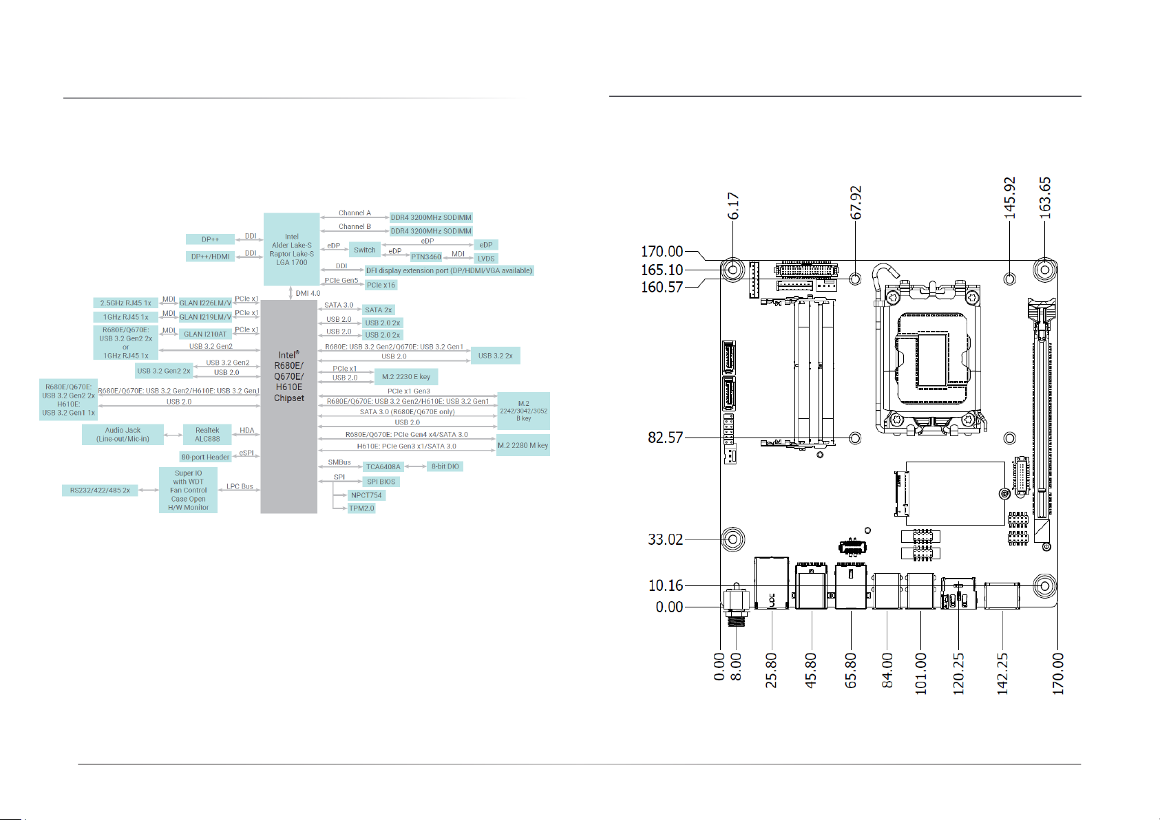
Block Diagram ........................................................................................................................9
Dimension...............................................................................................................................9
Chapter 2 - Hardware Installation..............................................................................................10
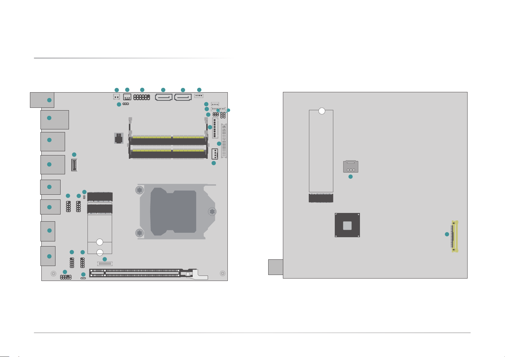
Board Layout.........................................................................................................................10
Jumper Settings...................................................................................................................12
Clear CMOS Data (JP5) ................................................................................................12
LVDS LCD Panel Power Supply (DPJP601).................................................................12
Power Level of LVDS LCD Inverter Connector (DPJP602) .........................................13
LCD Panel Power Supply (DPJP603) ...........................................................................13
USB Wake Up Select (DPJP604) ..................................................................................14
Pin Assignment....................................................................................................................15
Front Audio (AUJ2)........................................................................................................15
USB 2.0 5-6 (UBJ7)/8-9 Headers (UBJ8).....................................................................15
CPU Fan (J10)................................................................................................................16
Front Panel (J11)...........................................................................................................16
Digital I/O Power (J35) .................................................................................................17
Digital I/O (J13).............................................................................................................17
SATA Power (CN1) ........................................................................................................18
LCD/Inverter Power (DPJ601) ......................................................................................18
LVDS LCD Panel (DPCN601).........................................................................................19
eDP (CN23)...................................................................................................................20
COM1 & COM2 (J15 & J16)..........................................................................................21
SOJ1 (SOJ1) ..................................................................................................................21
Expansion Slots....................................................................................................................22
Installing the M.2 Module.............................................................................................22
Installing the SO-DIMM Module ...................................................................................24
Chapter 3 - BIOS Settings...........................................................................................................25
Overview ...............................................................................................................................25
Main.......................................................................................................................................26
Advanced .............................................................................................................................26
CPU Configuration.........................................................................................................27
Power & Performance...................................................................................................27
Power & Performance ►CPU- Power Management Control ..............................28
Power & Performance ►GT- Power Management Control.................................28
PCH-FW Configuration..................................................................................................29
Trusted Computing........................................................................................................29
PTN3460 Configuration ................................................................................................30
NCT6126D Super IO Configuration..............................................................................30
NCT6126D HW Monitor ................................................................................................31
NCT6126D HW Monitor ►Smart FAN Function .................................................31
Serial Port Console Redirection ...................................................................................32
Serial Port Console Redirection ►Console Redirection Settings........................32
ACPI Settings.................................................................................................................33
Network Stack Configuration........................................................................................34
NVMe Configuration......................................................................................................35
DFI WDT Configuration..................................................................................................35
USB Power Control........................................................................................................36
Tls Auth Configuration..................................................................................................36
Chipset..................................................................................................................................37
PEG Bifurcation..............................................................................................................37
System Agent (SA) Configuration................................................................................38
System Agent (SA) Configuration►Graphics Configuration................................38
PCH-IO Configuration....................................................................................................39
PCH-IO Configuration►PCI Express Configuration.............................................39
PCH-IO Configuration►SATA Configuration .......................................................40
PCH-IO Configuration►HD Audio Configuration.................................................40
Security .................................................................................................................................41
Secure Boot....................................................................................................................41
Boot.......................................................................................................................................42
Save & Exit............................................................................................................................42
Chapter 4 - RAID Settings...........................................................................................................43
RAID Levels...........................................................................................................................43
Setup Procedure...................................................................................................................43

4
User's Manual | ADS101_ADS103
About this Manual
This manual can be downloaded from the website.
The manual is subject to change and update without notice, and may be based on editions that
do not resemble your actual products. Please visit our website or contact our sales representa-
tives for the latest editions.
Warranty
1. Warranty does not cover damages or failures that occur from misuse of the product,
inability to use the product, unauthorized replacement or alteration of components and
product specifications.
2. The warranty is void if the product has been subjected to physical abuse, improper in-
stallation, modification, accidents or unauthorized repair of the product.
3. Unless otherwise instructed in this user’s manual, the user may not, under any circum-
stances, attempt to perform service, adjustments or repairs on the product, whether in
or out of warranty. It must be returned to the purchase point, factory or authorized ser-
vice agency for all such work.
4. We will not be liable for any indirect, special, incidental or consequential damages to
the product that has been modified or altered.
Static Electricity Precautions
It is quite easy to inadvertently damage your PC, system board, components or devices even
before installing them in your system unit. Static electrical discharge can damage computer
components without causing any signs of physical damage. You must take extra care in han-
dling them to ensure against electrostatic build-up.
1. To prevent electrostatic build-up, leave the system board in its anti-static bag until you
are ready to install it.
2. Wear an antistatic wrist strap.
3. Do all preparation work on a static-free surface.
4. Hold the device only by its edges. Be careful not to touch any of the components, con-
tacts or connections.
5. Avoid touching the pins or contacts on all modules and connectors. Hold modules or
connectors by their ends.
Safety Measures
• To avoid damage to the system, use the correct AC input voltage range.
• To reduce the risk of electric shock, unplug the power cord before removing the sys-
tem chassis cover for installation or servicing. After installation or servicing, cover the
system chassis before plugging the power cord.
Important:
Electrostatic discharge (ESD) can damage your processor, disk drive and other
components. Perform the upgrade instruction procedures described at an ESD
workstation only. If such a station is not available, you can provide some ESD pro-
tection by wearing an antistatic wrist strap and attaching it to a metal part of the
system chassis. If a wrist strap is unavailable, establish and maintain contact with
the system chassis throughout any procedures requiring ESD protection.

5
User's Manual | ADS101_ADS103
About the Package
The package contains the following items. If any of these items are missing or damaged,
please contact your dealer or sales representative for assistance.
• 1 ANS101/ADS103 Motherboard
• 1 Serial ATA data & power cable w/lock (Length: 300mm)
• 1 COM port cable (Length: 250mm, 1 x COM port)
• 1 I/O shield (w/ icon (3LAN/4USB) & w/ icon (2LAN/6USB))
The board and accessories in the package may not come similar to the information listed above.
This may differ in accordance with the sales region or models in which it was sold. For more
information about the standard package in your region, please contact your dealer or sales repre-
sentative.
Before Using the System Board
When installing the system board in a new system, you will need at least the following internal
components.
• Memory module
• Storage device such as a hard disk drive.
• Power supply
External system peripherals may also be required for navigation and display, including at least a
keyboard, a mouse and a video display monitor.

6
Chapter 1
INTRODUCTION
User's Manual | ADS101_ADS103
Chapter 1 - Introduction
X Specifications
SYSTEM Processor 14th Generation Intel®LGA 1700 Socket Processors, TDP support up to 65W
Intel®Core™ I9-14900 (24 Cores, 36M Cache, up to 5.8 GHz); 65W
Intel®Core™ I9-14900T (24 Cores, 36M Cache, up to 5.5 GHz); 35W
Intel®Core™ I7-14700 (20 Cores, 33M Cache, up to 5.4 GHz); 65W
Intel®Core™ I7-14700T (20 Cores, 33M Cache, up to 5.2 GHz); 35W
Intel®Core™ I5-14500 (14 Cores, 24M Cache, up to 5.0 GHz); 65W
Intel®Core™ I5-14500T (14 Cores, 24M Cache, up to 4.8 GHz); 35W
Intel®Core™ I5-14400 (10 Cores, 20M Cache, up to 4.7 GHz); 65W
Intel®Core™ I5-14400T (10 Cores, 20M Cache, up to 4.5 GHz); 35W
Intel®Core™ I3-14100 (4 Cores, 12M Cache, up to 4.7 GHz); 60W
Intel®Core™ I3-14100T (4 Cores, 12M Cache, up to 4.4 GHz); 35W
Intel®300 (2 Cores,6M Cache, 3.9 GHz); 46W
Intel®300T (2 Cores, 4M Cache, 3.4 GHz); 35W
13th Generation Intel®LGA 1700 Socket Processors, TDP support up to 65W
Intel®Core™ I9-13900E (24 Cores, 36M Cache, up to 5.2 GHz); 65W
Intel®Core™ I9-13900TE (24 Cores, 36M Cache, up to 5.0 GHz); 35W
Intel®Core™ I7-13700E (16 Cores, 30M Cache, up to 5.1 GHz); 65W
Intel®Core™ I7-13700TE (16 Cores, 30M Cache, up to 4.8 GHz); 35W
Intel®Core™ I7-13700T (16 Cores, 30M Cache, up to 4.9 GHz); 35W
Intel®Core™ I5-13500E (14 Cores, 24M Cache, up to 4.6 GHz); 65W
Intel®Core™ I5-13500TE (14 Cores, 24M Cache, up to 4.5 GHz); 35W
Intel®Core™ I5-13500T (14 Cores, 24M Cache, up to 4.6 GHz); 35W
Intel®Core™ I5-13400E (10 Cores, 20M Cache, up to 4.6 GHz); 65W
Intel®Core™ I3-13100E (4 Cores, 12M Cache, up to 4.4 GHz); 65W
Intel®Core™ I3-13100TE (4 Cores, 12M Cache, up to 4.1 GHz); 35W
Intel®Core™ I3-13100T (4 Cores, 12M Cache, up to 4.2 GHz); 35W
12th Generation Intel®LGA 1700 Socket Processors, TDP support up to 65W
Intel®Core™ i9-12900E (16 Cores, 30M Cache, up to 5.0 GHz); 65W
Intel®Core™ i9-12900TE (16 Cores, 30M Cache, up to 4.8 GHz); 35W
Intel®Core™ i7-12700E (12 Cores, 25M Cache, up to 4.8 GHz); 65W
Intel®Core™ i7-12700TE (12 Cores, 25M Cache, up to 4.6 GHz); 35W
Intel®Core™ i5-12500E (6 Cores, 18M Cache, up to 4.5 GHz); 65W
Intel®Core™ i5-12500TE (6 Cores, 18M Cache, up to 4.3 GHz); 35W
Intel®Core™ i3-12100E (4 Cores, 12M Cache, up to 4.2 GHz); 60W
Intel®Core™ i3-12100TE (4 Cores, 12M Cache, up to 4.0 GHz); 35W
Intel®Pentium®G7400E (2 Cores, 6M Cache, 3.6 GHz); 46W
Intel®Pentium®G7400TE (2 Cores, 6M Cache, 3.0 GHz); 35W
Intel®Celeron®G6900E (2 Cores, 4M Cache, 3.0 GHz); 46W
Intel®Celeron®G6900TE (2 Cores, 4M Cache, 2.4 GHz); 35W
Chipset Intel®R680E/Q670E/H610E Chipset

7
Chapter 1
INTRODUCTION
User's Manual | ADS101_ADS103
Memory Two 260-pin SODIMM up to 64GB
Dual Channel DDR4 3200 MHz (ECC support: R680E only)
BIOS AMI SPI 256Mbit
GRAPHICS Controller Intel®HD Gen 9 Graphics
Feature OpenGL 4.5, DirectX 12, OpenCL 2.1
HW Decode: AVC/H.264, MPEG2, VC1/WMV9, JPEG/MJPEG, HEVC/H265, VP8, VP9
HW Encode: MPEG2, AVC/H264, JPEG, HEVC/H265, VP8, VP9
Display 1 x DP++
1 x DP++/HDMI
1 x LVDS/eDP
1 x DFI display extension port (DP/HDMI/VGA available)
DP++: resolution up to 4096x2304 @60Hz
LVDS: resolution up to 1920x1200 @ 60Hz
eDP: resolution up to 4096x2160 @ 60Hz
Quad Displays DP++ + DP++/HDMI + LVDS/eDP + DFI display extension port (DP/HDMI/VGA available)
EXPANSION Interface 1 x PCIe x16 (Gen 5)
1 x M.2 2230 E Key (USB/PCIe x1)
R680E/Q670E:
1 x M.2 2280 M Key (PCIe Gen4 x4/SATA)
H610E:
1 x M.2 2280 M Key (PCIe Gen3 x1/SATA)
R680E/Q670E:
1 x M.2 2242/3042/3052 B Key (PCIe Gen3 x1/SATA/USB 3.2 Gen2/USB 2.0)
H610E:
1 x M.2 2242/3042/3052 B Key (SATA/USB 3.2 Gen1/USB 2.0)
AUDIO Audio Codec Realtek ALC888
ETHERNET Controller 1 x Intel®I226V PCIe(10/100/1000/2.5G speeds)
1 x Intel®I219LM PHY(10/100/1000 speeds) (support vPro/AMT) (H610E: I219V no supporting vPro/AMT)
1 x Intel®I210AT PCIe(10/100/1000 speeds)(Opt.)
REAR I/O Ethernet 1 x 2.5GbE (RJ-45)
1 x GbE (RJ-45) (2x by Opt.)
USB R680E/Q670E: 4 x USB 3.2 Gen2 (Opt.: up to 6 x USB 3.2 Gen2)
H610E: 2 x USB 3.2 Gen2 +1 x USB 3.2 Gen1+ 1 x USB 2.0
Display 1 x DP++
1 x DP++/HDMI
1 x DFI display extension for (DP/HDMI/VGA) (Opt.)
Audio 1 x Line-out
1 x Mic-in

8
Chapter 1
INTRODUCTION
User's Manual | ADS101_ADS103
INTERNAL I/O Serial 2 x RS-232/422/485 (without power) (2.54mm pitch)
USB 4 x USB 2.0 (2.54mm pitch)
2 x USB 3.2 Gen1 (R680E/Q670E only)
Display 1 x LVDS header
1 x eDP connector
Audio 1 x Front Audio Header
SATA 2 x SATA 3.0 (up to 6Gb/s)
1 x SATA Power
RAID 0/1/5/10 (w/ M.2 Key-M/B slot + 2 SATA Conn.)
DIO 1 x 8-bit DIO
WATCHDOG TIMER Output & Interval System Reset, Programmable via Software from 1 to 255 Seconds
SECURITY TPM dTPM2.0
POWER Type Single 12V +/-10% DC (ADS101)
Wide Range 15~36V (ADS103)
Connector DC-in Jack
Right Angle Connector (4-pin) (available upon request)
Straight Type Connector (4-pin) (available upon request)
Consumption TBD
RTC Battery CR2032 Coin Cell
OS SUPPORT Microsoft Windows 10 IoT Enterprise 64-bit
Linux Linux
ENVIRONMENT Temperature Operating: -5 to 65°C
Storage: -40 to 85°C
Humidity Operating: 5 to 90% RH
Storage: 5 to 90% RH
MTBF TBD
MECHANISM Dimensions Mini-ITX Form Factor: 170mm (6.7") x 170mm (6.7")
Height PCB: 1.6mm
Top Side: 33.3mm, Bottom Side: 4mm
STANDARDS AND CERTIFICATIONS Certifications CE, FCC Class B

9
Chapter 1
INTRODUCTION
User's Manual | ADS101_ADS103
X Block Diagram X Dimension

10
Chapter 2
HARDWARE INSTALLATION
User's Manual | ADS101_ADS103
Chapter 2 - Hardware Installation
X Board Layout
Front Panel
11
DDR4_1 SODIMM (Top)
DDR4_2 SODIMM (Bottom)
1
1
11
20
10
1 1
1
22
10 10
12
10
12
10
1
210
1
SPI
1
1
212
1
1
1
1
2
1 1
1 2
39
1
1
1
1
220
PCIe 1 x16
M2-B
M2-E
2
1
3
4
5
6
7
8
9
10 11
12 13
14
15
16
17 19 20 21 22 23
24
25
26
29
30
31
32
18
27
28
M2-M
M2CN15
33
34

11
Chapter 2
HARDWARE INSTALLATION
User's Manual | ADS101_ADS103
121
28
222
29
323
30
424
31
525
32
626
33
34
727
8
9
10
11
12
14
15
16
17
18
19
20
13
DC-in
LAN1
LAN2 / USB3.2 Gen2
LAN3
USB3.2 Gen2
USB3.2 Gen2
DP++ / HDMI
DP++
USB3_5/6
USB2_12/13
USB2_8/9
USB2_5/6
COM1
COM2
Front Audio
USB Wake Up Select
DDI
Battery
Clear CMOS Data
System Fan
Front Panel
SATA0
SATA1
SATA Power
DIO Power
DIO
LCD Panel Power Supply
Power Level of LVDS LCD Inverter Connector
LVDS LCD Panel Power Supply
LVDS Power
LVDS
CPU Fan
SOJ1
eDP
SIM Card Slot

12
Chapter 2
HARDWARE INSTALLATION
User's Manual | ADS101_ADS103
X Jumper Settings
Clear CMOS Data (JP5) LVDS LCD Panel Power Supply (DPJP601)
Front Panel
11
DDR4_1 SODIMM (Top)
DDR4_2 SODIMM (Bottom)
1
1
11
20
10
1 122
10 10
12
10
12
10
1
210
1
SPI
1
1
212
1
1
1
1
2
1 1
1 2
39
1
1
1
1
220
PCIe 1 x16
M2-B
M2-E
1
Front Panel
11
DDR4_1 SODIMM (Top)
DDR4_2 SODIMM (Bottom)
1
1
11
20
10
1 122
10 10
12
10
12
10
1
210
1
SPI
1
1
2
12
1
1
1
1
2
1 1
1 2
39
1
1
1
1
220
PCIe 1 x16
M2-B
M2-E
1
1-2 On: 3V3 (Default)
1-2 On: Normal (Default) 2-3 On: 5V
2-3 On: Clear CMOS Data
1
11
1
1
1

13
Chapter 2
HARDWARE INSTALLATION
User's Manual | ADS101_ADS103
Power Level of LVDS LCD Inverter Connector (DPJP602) LCD Panel Power Supply (DPJP603)
Front Panel
11
DDR4_1 SODIMM (Top)
DDR4_2 SODIMM (Bottom)
1
1
11
20
10
1 122
10 10
12
10
12
10
1
210
1
SPI
1
1
2
12
1
1
1
1
2
1 1
1 2
39
1
1
1
1
220
PCIe 1 x16
M2-B
M2-E
1
Front Panel
11
DDR4_1 SODIMM (Top)
DDR4_2 SODIMM (Bottom)
1
1
11
20
10
1 122
10 10
12
10
12
10
1
210
1
SPI
1
1
2
12
1
1
1
1
2
1 1
1 2
39
1
1
1
1
220
PCIe 1 x16
M2-B
M2-E
1
1-2 On: +12V (Default) 2-3 On: +5V
11
1
1
2
6
5
2
1
6
5
2
1
1-2 On: +12V 3-4 On: +5V 5-6 On: +3.3V (Default)
6
5
2
1

14
Chapter 2
HARDWARE INSTALLATION
User's Manual | ADS101_ADS103
USB Wake Up Select (DPJP604)
Front Panel
11
DDR4_1 SODIMM (Top)
DDR4_2 SODIMM (Bottom)
1
1
11
20
10
1 122
10 10
12
10
12
10
1
210
1
SPI
1
1
2
12
1
1
1
1
2
1 1
1 2
39
1
1
1
1
220
PCIe 1 x16
M2-B
M2-E
1
1-2 On: 5VSB (Default) 2-3 On: 5V
11
1

15
Chapter 2
HARDWARE INSTALLATION
User's Manual | ADS101_ADS103
X Pin Assignment
Front Audio (AUJ2) USB 2.0 5-6 (UBJ7)/8-9 Headers (UBJ8)
Front Panel
11
DDR4_1 SODIMM (Top)
DDR4_2 SODIMM (Bottom)
1
1
11
20
10
1 122
10 10
12
10
12
10
1
210
1
SPI
1
1
212
1
1
1
1
2
1 1
1 2
39
1
1
1
1
220
PCIe 1 x16
M2-B
M2-E
1
Front Panel
11
DDR4_1 SODIMM (Top)
DDR4_2 SODIMM (Bottom)
1
1
11
20
10
1 122
10 10
12
10
12
10
1
210
1
SPI
1
1
212
1
1
1
1
2
1 1
1 2
39
1
1
1
1
220
PCIe 1 x16
M2-B
M2-E
1
1
210
Pin Assignment Pin Assignment
1Mic-L 2GND
3Mic-R 4NC
5Line-Out-R 6Mic-JD (sense)
7GND 8KEY
9Line-Out-L 10 Line-JD (sense)
1 122
10 10
USB2_5/6
USB2_8/9
Pin Assignment Pin Assignment
1PWR 2PWR
3DATA- 4DATA-
5DATA+ 6DATA+
7GND 8GND
9--- 10 NC

16
Chapter 2
HARDWARE INSTALLATION
User's Manual | ADS101_ADS103
CPU Fan (J10) Front Panel (J11)
Front Panel
11
DDR4_1 SODIMM (Top)
DDR4_2 SODIMM (Bottom)
1
1
11
20
10
1 122
10 10
12
10
12
10
1
210
1
SPI
1
1
212
1
1
1
1
2
1 1
1 2
39
1
1
1
1
220
PCIe 1 x16
M2-B
M2-E
1
Front Panel
11
DDR4_1 SODIMM (Top)
DDR4_2 SODIMM (Bottom)
1
1
11
20
10
1 122
10 10
12
10
12
10
1
210
1
SPI
1
1
212
1
1
1
1
2
1 1
1 2
39
1
1
1
1
220
PCIe 1 x16
M2-B
M2-E
1
Pin Assignment
1GND
2Power
3Sense
4Speed Control
1
1
212
Pin Assignment Pin Assignment
1NC
PWR-LED
2LED Power
HD-LED
3HDD Power 4LED Power
5Signal 6Signal
RESET
7GND
ATX-SW
8GND
9Signal 10 Signal
11 NC 12 ---

17
Chapter 2
HARDWARE INSTALLATION
User's Manual | ADS101_ADS103
Digital I/O Power (J35) Digital I/O (J13)
Front Panel
11
DDR4_1 SODIMM (Top)
DDR4_2 SODIMM (Bottom)
1
1
11
20
10
1 122
10 10
12
10
12
10
1
210
1
SPI
1
1
212
1
1
1
1
2
1 1
1 2
39
1
1
1
1
220
PCIe 1 x16
M2-B
M2-E
1
Front Panel
11
DDR4_1 SODIMM (Top)
DDR4_2 SODIMM (Bottom)
1
1
11
20
10
1 122
10 10
12
10
12
10
1
210
1
SPI
1
1
2
12
1
1
1
1
2
1 1
1 2
39
1
1
1
1
220
PCIe 1 x16
M2-B
M2-E
1
Pin Assignment
1+12V
2GND
35VSB
4+5V
1
Pin Assignment
1DIO0
2DIO1
3DIO2
4DIO3
5DIO4
6DIO5
7DIO6
8DIO7
1

18
Chapter 2
HARDWARE INSTALLATION
User's Manual | ADS101_ADS103
SATA Power (CN1) LCD/Inverter Power (DPJ601)
Front Panel
11
DDR4_1 SODIMM (Top)
DDR4_2 SODIMM (Bottom)
1
1
11
20
10
1 122
10 10
12
10
12
10
1
210
1
SPI
1
1
212
1
1
1
1
2
1 1
1 2
39
1
1
1
1
220
PCIe 1 x16
M2-B
M2-E
1
Front Panel
11
DDR4_1 SODIMM (Top)
DDR4_2 SODIMM (Bottom)
1
1
11
20
10
1 122
10 10
12
10
12
10
1
210
1
SPI
1
1
2
12
1
1
1
1
2
1 1
1 2
39
1
1
1
1
220
PCIe 1 x16
M2-B
M2-E
1
Pin Assignment
1+12V
2GND
3GND
45V
1
1
Pin Assignment
1GND
2GND
3Panel Inverter Brightness Voltage Control
4Panel Power
5+3.3V
6Panel Backlight On/O Control
7LCD/Inverter Power
8LCD/Inverter Power

19
Chapter 2
HARDWARE INSTALLATION
User's Manual | ADS101_ADS103
LVDS LCD Panel (DPCN601)
Front Panel
11
DDR4_1 SODIMM (Top)
DDR4_2 SODIMM (Bottom)
1
1
11
20
10
1 122
10 10
12
10
12
10
1
210
1
SPI
1
1
212
1
1
1
1
2
1 1
1 2
39
1
1
1
1
220
PCIe 1 x16
M2-B
M2-E
1
39
12
Pin Assignment Pin Assignment
1GND 2GND
3LVDSA_3+ 4LVDSB_3+
5LVDSA_3- 6LVDSB_3-
7GND 8GND
9LVDSA_2+ 10 LVDSB_2+
11 LVDSA_2- 12 LVDSB_2-
13 GND 14 GND
15 LVDSA_1+ 16 LVDSB_1+
17 LVDSA_1- 18 LVDSB_1-
19 GND 20 GND
21 LVDSA_0+ 22 LVDSB_0+
23 LVDSA_0- 24 LVDSB_0-
25 GND 26 GND
27 LVDSA_CLK+ 28 LVDSB_CLK+
29 LVDSA_CLK- 30 LVDSB_CLK-
31 GND 32 GND
33 DDC_CLK 34 NC
35 DDC_DATA 36 +3.3V
37 Panel Power 38 Panel Power
39 Panel Power 40 Panel Power

20
Chapter 2
HARDWARE INSTALLATION
User's Manual | ADS101_ADS103
eDP (CN23)
M2-M
M2CN15
Pin Assignment Pin Assignment
1NC 21 eDP_PANEL_PWR
2VCC_INV_PWR 22 eDP_PANEL_PWR
3VCC_INV_PWR 23 eDP_PANEL_PWR
4VCC_INV_PWR 24 GND
5VCC_INV_PWR 25 eDP_AUXN_C
6NC 26 eDP_AUXP_C
7NC 27 GND
8DIMMING 28 eDP_LANE0_P
9BLONOFF 29 eDP_LANE0_N
10 GND 30 GND
11 GND 31 eDP_LANE1_P
12 GND 32 eDP_LANE1_N
13 GND 33 GND
14 eDP_HDP_C 34 eDP_LANE2_P
15 GND 35 eDP_LANE2_N
16 GND 36 GND
17 GND 37 eDP_LANE3_P
18 GND 38 eDP_LANE3_N
19 NC 39 GND
20 eDP_PANEL_PWR 40 NC
This manual suits for next models
1
Table of contents
Other DFI Motherboard manuals