www.df .com
3
Chapter 1 Introduction
Table of Contents
Copyright .............................................................................................................2
Trademarks ........................................................................................................2
FCC and DOC Statement on Class A ..................................................... 2
About this Manual ..........................................................................................4
Warranty ..............................................................................................................4
Static Electricity Precautions ......................................................................4
Safety Measures ..............................................................................................4
Safety Precautions ..........................................................................................5
About the Package .........................................................................................5
Chapter 1 - Introduction .............................................................................6
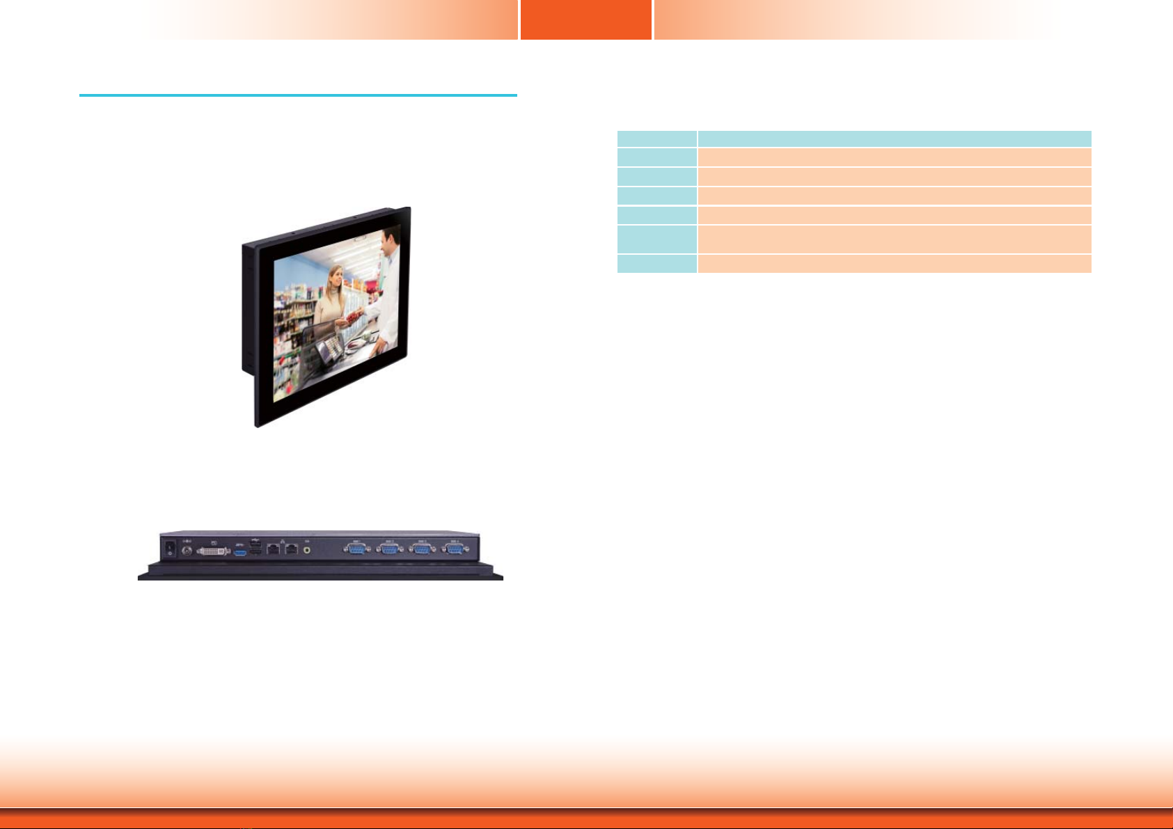
Overview.........................................................................................................6
Key Features.................................................................................................. 6
Specifications ................................................................................................7
Getting to Know the KS150-B T ................................................................ 8
Mechanical Dimensions ..............................................................................8
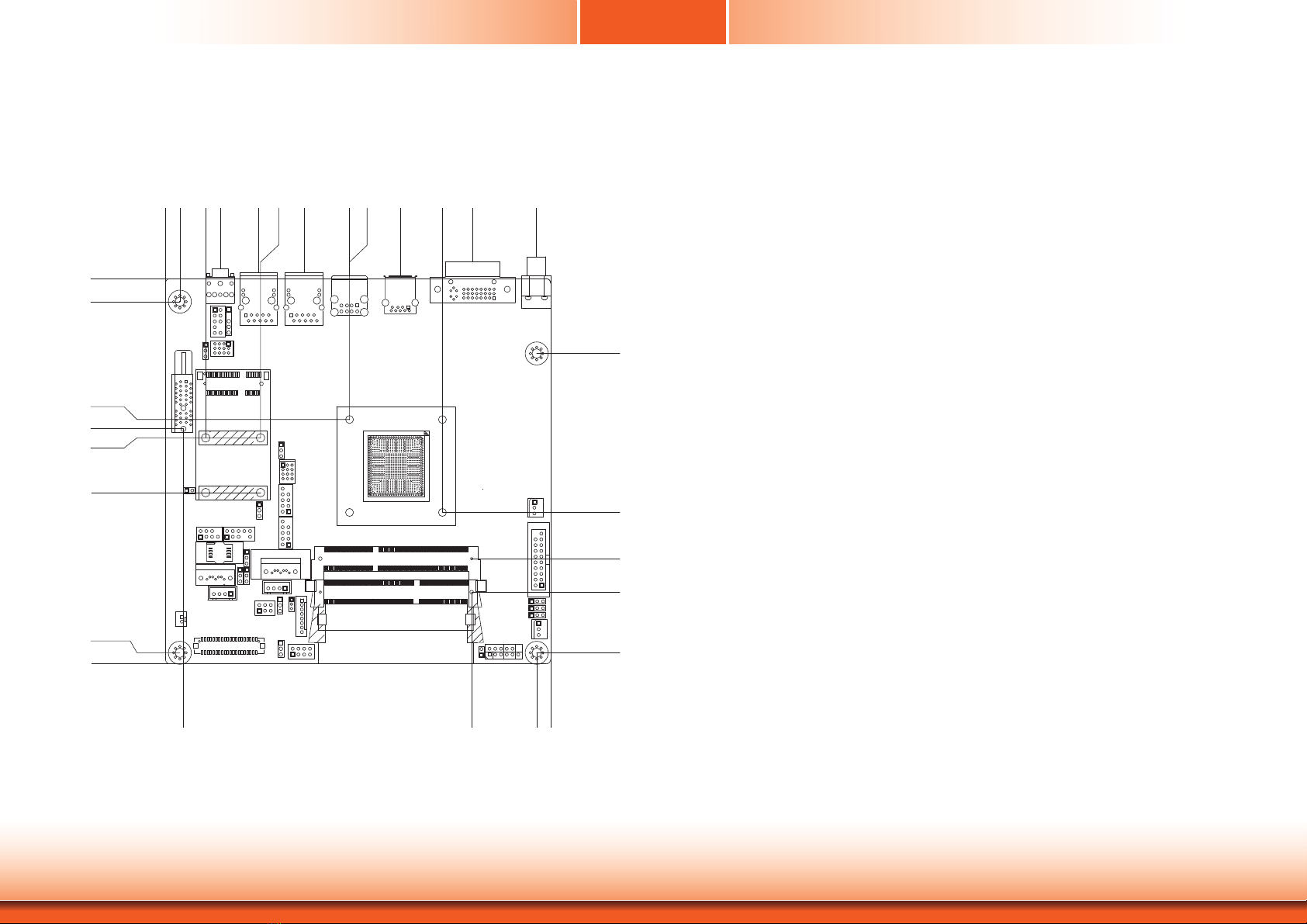
Motherboard Dimensions ...........................................................................9
Chapter 2 - Get ting Started ..................................................................... 10
Preparing the System ...............................................................................10
Installing Devices .......................................................................................10
Configuring the BIOS ................................................................................ 10
Installing the Operating System ............................................................10
Installing the Drivers ................................................................................ 10
Chapter 3 - Installing Devices ................................................................11
Removing the Chassis Co ver ..................................................................11
Installing the SODIMM .............................................................................12
Installing the SATA Drive .........................................................................13
Chapter 4 - Jumper Set tings ...................................................................15
Clear CMOS Data ........................................................................15
PS/2 Keyboard/Mouse Power Select ............................................15
USB Power Select ........................................................................16
LCD/Inverter Power Select ..........................................................16
Panel Power Select ......................................................................17
Backlight Power Select ................................................................17
Auto Power-on Select ..................................................................18
SATA DOM Power Select..............................................................18
COM 1 RS232/422/485 Select .....................................................19
COM 1 RS232/Power Select .......................................................20
Digital I/O Power Select ..............................................................20
Digital I/O Output State ..............................................................21
Mini PCIe/mSATA Signal Select ....................................................21
Mini PCIe/mSATA Power Select ...................................................22
SATA 1/mSATA Sinal Select .........................................................22
Dimming Mode Select ..................................................................23
Chapter 5 - P orts and Connectors .............................................. 24
Bottom Panel I/O Ports ............................................................................24
12V DC-in .................................................................................................. 24
Graphics Interface ...................................................................................... 25
RJ45 LAN Ports ........................................................................................... 25
USB Ports ................................................................................................... 26
Audio .........................................................................................................27
I/O Connectors ...........................................................................................27
SATA (Serial ATA) Connectors ...................................................................... 27
SATA (Serial ATA) Power Connectors ............................................................ 28
Digital I/O and/or P ower Connector ............................................................. 28
Cooling Fan Connectors............................................................................... 29
Front Panel Connector ................................................................................ 29
COM (Serial) Ports ...................................................................................... 30
LVDS LCD Panel Connector ......................................................................... 31
LCD/Inverter Power Connector .................................................................... 31
PS/2 Keyboard/Mouse Connector ................................................................. 32
SMBus Connector (optional) ........................................................................ 33
Expansion Slots .......................................................................................... 33
S/PDIF Connector ....................................................................................... 34
LAN LED Connector .................................................................................... 34
Chassis Intrusion Connector ........................................................................ 35
Standby Power LED .................................................................................... 35
Battery ....................................................................................................... 36
Chapter 6 - Mounting Options .................................................... 37
Chapter 7 - BIOS Setup ............................................................................ 40
Overview....................................................................................................... 40
AMI BIOS Setup Utilit y .............................................................................41
Updating the BIOS .................................................................................... 57
Notice: BIOS SPI ROM .............................................................................57
Chapter 8 - Supported Softw are ...........................................................58
Chapter 9 - Digital I/O Progr amming Guide .................................... 71
Appendix A - W atchdog Sample Code ................................................ 73
Appendix B - S ystem Error Message ...................................................74
Appendix C - Troubleshooting Checklist ............................................76