manuals.online logo
Brands
  1. Home
  2. •
  3. Brands
  4. •
  5. DINUY
  6. •
  7. Security Sensor
  8. •
  9. DINUY KNX DM KNT 003 User manual

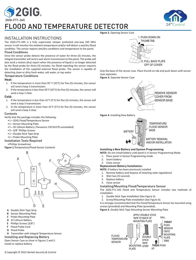
DINUY KNX DM KNT 003 User manual

GB
8-CHANNEL BINARY INPUT
TECHNICAL DATA
DESCRIPTION
The interface EM KNT 003 is equipped with 8 Digital (Binary) independent
inputs which may be conmnected to a conventional push-button, switch or
binary sensor with free-voltage contact.
Each of the 4 channels has the following configurable functions with the
ETS:
- Switch: to turn the light ON and OFF.
- Switch and Dimmer: to turn ON/OFF and dim the light.
- Multiple Switch: to turn ON/OFF the light depending on the number of
press.
- Sequential Switch: to do sequential switching ON/OFF.
- Blinds/Shutters Control: to move the blinds/shutter by push buttons or
switches.
- Scenes Control: to save and recover a light scene.
- Values Sending: to send different measures or values, for example the
light level, temperature,...
- Impulse Counter: it allows, for example, counting the number of
operations.
It incorporates the KNX Bus Coupling Unit (BCU).
Power supply 21 ~ 32VDC (via Bus)
Power consumption < 5mA
Wires length ~ 30cm
Connection Connecting terminal
Number of Inputs 8
Type of Inputs Binary
Dimensions 38 x 42 x 15mm
Operation temperature -5ºC ~ +45ºC
Type of protection IP20 (EN60529)
Directives Low-voltage 2011/65/EU
EMC 2014/30/EU
According to the Standards KNX Standard 2.0
UNE-EN 50491-3:2010
UNE-EN 50491-4-1:2013
UNE-EN 50491-5-2:2010
Max. Line length < 200m
Commissioning ETS5 or later
E
ENTRADA BINARIA DE 8 CANALES
ESPECIFICACIONES TÉCNICAS
Tensión Alimentación 21 ~ 32Vcc (a través del Bus)
Consumo < 5mA
Longitud Cables ~ 30cm
Conexión al Bus KNX Mediante terminal de conexión
Nº de Entradas 8
Tipo de Entradas Binarias
Dimensiones 38 x 42 x 15mm
Tª Funcionamiento -5ºC ~ +45ºC
Grado Protección IP20 (EN60529)
De acuerdo a las Directivas Seguridad 2011/65/EU
Comp. Electromagn. 2014/30/EU
De acuerdo a las Normas KNX Standard 2.0
UNE-EN 50491-3:2010
UNE-EN 50491-4-1:2013
UNE-EN 50491-5-2:2010
Marking EIB/KNXCertificación EIB/KNX
Longitud Línea Máx. < 200m
Programación a través de ETS5 o superior
DESCRIPCIÓN
Interfaz con 8 entradas digitales (binarias), las cuales pueden ser
conectadas conexión a un pulsador, un interruptor o un sensor binario
convencional, libre de potencial.
Cada uno de los 8 canales dispone de las siguientes funciones
configurables con el ETS:
- Interruptor: para el encendido y apagado de la iluminación.
- Interruptor y Regulador: para el encendido, apagado y regulación de la
iluminación.
- Interruptor Múltiple: para el encendido y apagado de la iluminación en
función del número de pulsaciones.
- Interruptor Secuencial: apagado o encendido secuencial.
- Control de Persianas/Toldos: para el control, mediante pulsadores o
interruptores, de la subida y bajada de persianas, con o sin lamas.
- Control Escenas: para el guardado y recuperación de escenas de
iluminación.
- Envío de valores: para el envío de valores concretos, por ejemplo, de
niveles de iluminación.
- Contador de impulsos: permite contar, por ejemplo, cuantas maniobras
se realizan.
Incorpora la Unidad de Acoplamiento al Bus (BCU) KNX.
EM KNT 003
A
B
C
DINUY S.A.
c/Auzolan Nº2
20303 Irún (Spain)
info@dinuy.com
www.dinuy.com
Entrada 1
Entrada 2
Entrada 3
Entrada 4
Entrada 5
Entrada 6
Entrada 7
Entrada 8
Común Entradas
INSTALACIÓN
El interfaz universal EM KNT 003 dispone de un conector estándar (A) para
su conexión al Bus.
Para la conexión de las entradas digitales se dispone de un conector (C)
con 9 cables de diferentes colores, los cuales corresponden a las 8
entradas digitales y al común de las mismas.
Se muestran un ejemplo de conexión:
· Ej. 1: conexión de 8 pulsadores o interruptores.
PUESTA EN MARCHA
Para realizar la programación de la dirección física a través del ETS, es
necesario pulsar el botón de programación (B). En el momento de pulsarlo
el LED rojo (B) se encenderá indicando que está en modo de programación.
El funcionamiento del producto está condicionado a la parametrización
realizada mediante el ETS. Puede descargarse el software en nuestra
página web: www.dinuy.com.
Para la instalación y puesta en marcha del aparato, siga los siguientes
pasos:
1º - Cablee el interfaz según el esquema de conexión mostrado
anteriormente.
2º - Conecte el interfaz al Bus KNX.
3º - Asigne dirección física y parametrice el programa de aplicación.
4º - Presione el botón de programación y programe la dirección física y la
aplicación.
5º - Una vez que se haya programado, el LED rojo se apagará
automáticamente.
INDICACIONES DE SEGURIDAD:
No está permitido conectar señales con tensión a las entradas.
Únicamente conecte pulsadores, interruptores o sensores libres de
tensión.
Para evitar interferencias, los cables de las entradas no deben
instalarse junto a cables de red ni de carga.
La instalación de aparatoseléctricos debe ser efectuada por
personal cualificado.
En la siguiente tabla se muestra la asignación de cables:
INSTALLATION
The universal interface EM KNT 003 has a standard Bus connecting
terminal (A).
A connector is available for the connection of the inputs and outputs (C) with
6 wires of different colors, which correspond to the 8 digital inputs and
common of the same.
One connection example is shown:
· Ej. 1: connection of 8 pushbuttons or switches.
COMMISSIONING
In order to set the physical address using the ETS, press the programmation
pushbutton (B). The red LED will switch on.
The functions of the device depend on the parameter settings set with the
ETS.
The software can be downloaded from our internet site: www.dinuy.com.
For the installation and commissionig of the device, follow these steps:
1º - Wire the interface according to the connection diagram, based on the
requirements.
2º - Connect the interface to the Bus.
3º - Assign physical address and parametize the application program.
4º - Press the program button and set the physical address and the
application of the device.
5º - Once it has been programmed, the red LED will be automatically turned
off.
SAFETY WARNINGS:
It is not permitted to connect 230V signals or other voltages to the
inputs.
Connect only voltage-free pushbuttons, switches, DINUY
temperature probes or the motion detector DM KNT 004.
In order to prevent interferences, do not run the wires of the inputs in
parallel with mains voltage lines or load lines.
Electrical equipments must be installed by qualified electricians.
The following table shows the cable assignment of the inputs:
WARNING!:
Installation and assembly of electrical equipment must be carried out only by a
skilled person!
Connect only to suitable supply voltage (KNX bus voltage)!
Installation and assembly of electrical equipment must be in accordance with
national building, electrical and safety codes!
¡ATENCIÓN!:
¡La instalación y el montaje de los equipos eléctricos solo debe ser realiza por
una persona cualificada!
¡Conectar solo a la tensión de alimentación correcta (tensión de bus KNX)!
¡La instalación y el montaje del equipo eléctrico deben realizarse de acuerdo
con las directivas nacionales de edificación, eléctricas y de seguridad!
Ej. 1
12 3 45 6 7 8 V
In_1
In_2
In_3
In_4
In_5
In_6
In_7
In_8
GB E
1
2
3
4
5
6
7
8
V
Input 1
Input 2
Input 3
Input 4
Input 5
Input 6
Input 7
Input 8
Common
1
2
3
4
5
6
7
8
V
Other manuals for KNX DM KNT 003

2

Other DINUY Security Sensor manuals

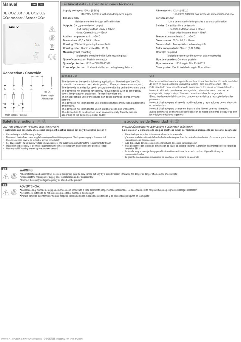
DINUY SE CO2 001 User manual

DINUY

DINUY SE CO2 001 User manual

DINUY DM KNX 002 User manual

DINUY

DINUY DM KNX 002 User manual

DINUY DM KNX 001 User manual

DINUY

DINUY DM KNX 001 User manual

DINUY DM KNT 002 User manual

DINUY

DINUY DM KNT 002 User manual

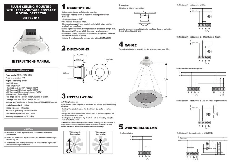
DINUY DM TEC 011 User manual

DINUY

DINUY DM TEC 011 User manual

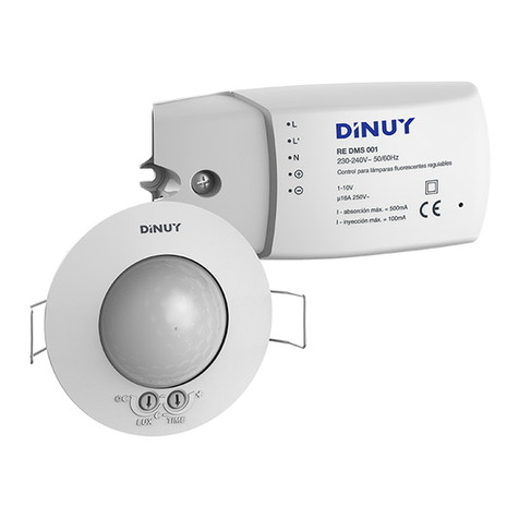
DINUY RE DMS 001 User manual

DINUY

DINUY RE DMS 001 User manual

DINUY KNX DM KNT 003 User manual

DINUY

DINUY KNX DM KNT 003 User manual

DINUY DP KNX 001 User manual

DINUY

DINUY DP KNX 001 User manual

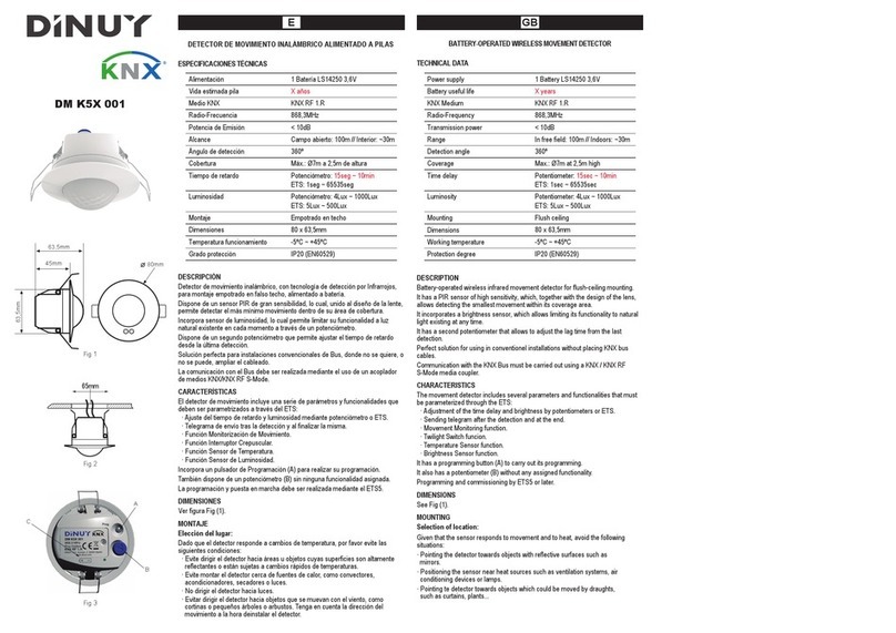
DINUY DM K5X 001 User manual

DINUY

DINUY DM K5X 001 User manual

DINUY DM SEN R02 User manual

DINUY

DINUY DM SEN R02 User manual

DINUY DM TEC 008 User manual

DINUY

DINUY DM TEC 008 User manual

DINUY KNX DM KNT 003 User manual

DINUY

DINUY KNX DM KNT 003 User manual

DINUY DM TEC 243 User manual

DINUY

DINUY DM TEC 243 User manual

Popular Security Sensor manuals by other brands

Sferalabs Exo Sense RP user guide

Sferalabs

Sferalabs Exo Sense RP user guide

HIK VISION DS-PDSMK-S-WB quick start guide

HIK VISION

HIK VISION DS-PDSMK-S-WB quick start guide

Guard master CU3 installation instructions

Guard master

Guard master CU3 installation instructions

B-Link SEMACONNECT 7 Series installation manual

B-Link

B-Link SEMACONNECT 7 Series installation manual

Promax PROLITE-3O user guide

Promax

Promax PROLITE-3O user guide

Paradox NV35MX installation manual

Paradox

Paradox NV35MX installation manual

C.P. Electronics GENB-IR installation guide

C.P. Electronics

C.P. Electronics GENB-IR installation guide

Green Brook Orion OD104 quick start guide

Green Brook

Green Brook Orion OD104 quick start guide

Paradox Paradome DG467 user manual

Paradox

Paradox Paradome DG467 user manual

GST DI-9104Exd quick start guide

GST

GST DI-9104Exd quick start guide

TIF TIF5050A owner's manual

TIF

TIF TIF5050A owner's manual

Honeywell C7061A1020 manual

Honeywell

Honeywell C7061A1020 manual

Datalogic SG2 BASE Series Original instructions

Datalogic

Datalogic SG2 BASE Series Original instructions

Emerson Net Safety JB Series Reference manual

Emerson

Emerson Net Safety JB Series Reference manual

Evikon PluraSens E2608-NH3 user manual

Evikon

Evikon PluraSens E2608-NH3 user manual

MSA S-Cap-Air operating manual

MSA

MSA S-Cap-Air operating manual

Abus FUBW50110 quick start guide

Abus

Abus FUBW50110 quick start guide

Axis T8331-E installation guide

Axis

Axis T8331-E installation guide

manuals.online logo
manuals.online logoBrands
  • About & Mission
  • Contact us
  • Privacy Policy
  • Terms and Conditions

Copyright 2025 Manuals.Online. All Rights Reserved.