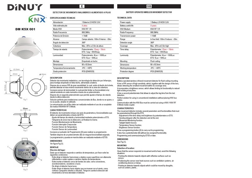
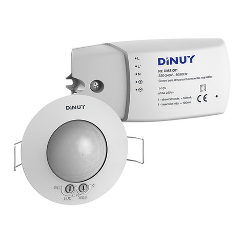
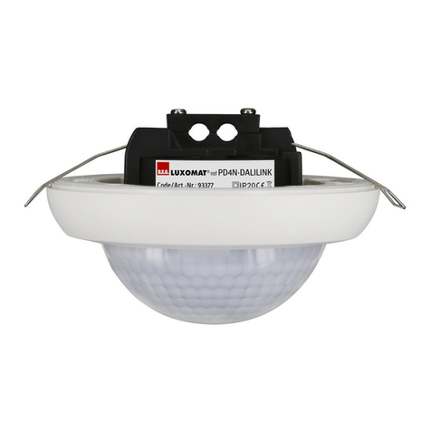
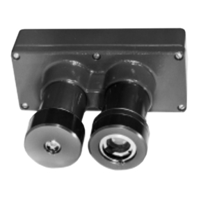
DINUY DM KNX 001 User manual

EGB F
DETECTOR DE MOVIMIENTO INALÁMBRICO
ESPECIFICACIONES TÉCNICAS
TensiónAlimentación 1 batería de Litio (incluída)
Duración Pila (estimada) > 4 años (50det/día a 25ºC)
Radio-Frecuencia Emisión codificada en 868,4MHz
con PRA>8mW y una penetración
de 100m (campo abierto)
Compatible con KNX-RF
ProtecciónAmbiental IP20
Tª Funcionamiento 0ºC ~ +45ºC
Cobertura 360º y
Ø
6m a 2.4m de altura
DESCRIPCIÓN
Sensor de movimiento que detecta cambios de temperatura, por infrarrojos (PIR),
dentro de su área de cobertura.
Dispone de sensor de luz, lo que permite limitar el funcionamiento en función de la
luz natural que haya.
En el momento que detecta movimiento, envía la señal de activación al receptor RF
asociado y mantiene su contacto cerrado durante el tiempo fijado en el propio
receptor.
Con cada detección de movimiento, el aparato envía la señal al actuador asociado
y se rearma el tiempo.
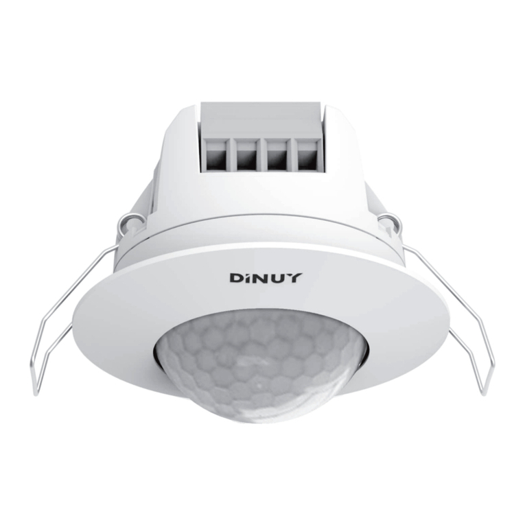
Montaje empotrado en el techo.
Construcción tipo foco, fácil instalación en techos con diferente espesor.
Diseño único en las lentes. Distribuye un total de 304 zonas en sus 360º de alta
intensidad de detección, sin ángulos muertos.
Incorpora LED, que se ilumina al detectar movimiento.
COBERTURA
Se recomienda que el montaje del detector se efectúe a una altura de 2.4m,
consiguiendo de esta forma un área de detección máximo de Ø6m.
INSTALACIÓN
A. Elección del lugar:
Debido a que el detector responde a cambios de temperatura, por favor evite las
siguientes condiciones:
· Evite dirigir el detector hacia áreas u objetos cuyas superficies son altamente
reflectantes o están sujetas a cambios rápidos de temperaturas.
· Evite montar el detector cerca de fuentes de calor, como convectores,
aparatos de aire acondicionado, luces...
· Evite dirigir el detector hacia fuentes de luz.
· Evitar dirigir el detector hacia objetos que se muevan con el viento, como
cortinas o pequeños árboles o arbustos.
B. Modo de instalación:
Para instalar el detector:
1. Taladrar en el techo un orificio de 65mm de diámetro.
2. Insertar el detector dentro del orificio de instalación.
3. Limpiar con un paño limpio y seco la superficie del detector.
AJUSTE Y PRUEBA DE FUNCIONAMIENTO
A. Ajuste de la cabeza del detector
Nota: Tirar suavemente hacia fuera de la cabeza del detector con un destornillador
antes de su ajuste.
Puede ajustar la cabeza del detector hasta que cumpla con sus necesidades de
cobertura.
Se puede ajustar horizontalmente hasta 350º (en pasos de 30º) y verticalmente
hasta 30º (en pasos de 5º) .
DM KNX 001
WIRELESS MOTION DETECTOR
TECHNICAL DATA
Power supply 1 Lithium battery (included)
Battery life (estimeed) > 4 years (50det/day at 25ºC)
Radio-Frequency Codified transmission in 868,4MHz
with ERP>8mW and a coverage of
100m (in the free field)
Compatible with RF-KNX
Protection degree IP20
Working temperature 0ºC ~ +45ºC
Coverage 360º &
Ø
6m at 2.4m high
DESCRIPTION
Motion sensor which detects temperature changes (PIR) in its coverage area.
Built-in brightness sensor which permits to limit the detection to the daylight.
As soon as it detects movement it sends an ON signal to the linked actuator and
keeps its contact closed for the time set on the actuator.
With each detection the sensor sends the telegram to the actuator and restart the
delay time.
Flush ceiling mounting.
Easy installation in ceilings with different thickness.
Built-in LED which indicates motion has been detected.
COVERAGE
It is recommended mounting the detector at 3m high, getting in this way a maximum
coverage of Ø6m.
INSTALLATION
A. Select a proper place:
Since the sensor responds to temperature changes, please avoid following
conditions:
·Avoid aiming the sensor towards areas or objects whose surfaces are highly
reflective or are subject to quick temperature changes, such as pools.
·Avoid mounting the sensor close heat sources, such as heatings vents, air
conditioning machines, dryers, vents or lights.
·Avoid aiming the sensor towards any type of light.
·Avoid aiming the sensor towards objects which may move by wind, such as
curtains, trees or bushes.
B. Installation procedure:
1. Open a Ø65mm hole on the ceiling.
2. Insert the sensor inside the hole.
3.Adjust the sensor’s position. Be sure that bottom of sensor is tightly stacked on
the ceiling.
SETTINGS AND TEST
A. Adjust sensor’s head
Note: Pull out sensor’s head gently with a screwdriver before it adjustment.
Sensor’s head can be adjusted up to fulfil with the coverage needs.
Can be horizontally adjusted up to 350º (by steps of 30º) and vertically up to 30º
(by steps of 5º).
3m 3m 6m
5 - 25mm

FGB E
DINUY S.A.
c/Auzolan Nº2
20303 Irún (Spain)
info@dinuy.com
www.dinuy.com
B. Función LED
El LED puede servir como indicador cuando se realiza la prueba de
funcionamiento.
C. Cómo realizar la prueba
1. Dirigir el detector hacia la zona que se quiere cubrir.
2. Encender el detector.
3. Esperar un mínimo de 30 segundos con el detector encendido.
4. Caminar desde fuera del área de cobertura hacia dentro hasta que se produzca
la detección.
5.Ajustar la cabeza del detector cuanto sea necesario para cambiar la cobertura.
6. Repetir los pasos 4 y 5 hasta alcanzar la cobertura deseada.
D. Potenciómetro LUX. Ajuste de iluminación
Se puede ajustar un nivel de iluminación por encima del cual el detector de
movimiento no emitirá señal.
En caso de querer anular esta función de manera que el detector emita siempre
situar el potenciómetro LUX al máximo.
E. Conmutador ON / OFF
· ON - encendido
· OFF - apagado
CODIFICACIÓN ENTRE DETECTOR Y RECEPTOR
A. Enlace del detector con un receptor
Estos detectores pueden asociarse a diferentes tipos de receptores. La codificación
tiene dos partes, una asociada al propio detector y otra asociada al receptor,
explicada en las instrucciones de cada receptor.
Para que el receptor aprenda el código del detector de movimiento, hay que seguir
los siguientes pasos:
1.-Activar el modo programación en el receptor RF (según las instrucciones del
fabricante).
2.-Activar el modo programación en el detector RF, para lo cual situar el selector
ON/OFF en la posición ON.
3.- El detector envia una señal al receptor asociado.
4.- Desconectar el detector ya codificado situando el selector ON/OFF en la
posicion OFF para evitar interferencias si se quieren codificar más detectores.
5.- Una vez codificados todos los detectores con el receptor asociado, situar el
selector ON/OFF de todos ellos en la posición ON para su funcionamiento
normal.
B. Borrado de un enlace
Para borrar un enlace entre un detector y un receptor RF, siga los siguientes pasos:
1.-Activar el modo borrado de un enlace en el receptor RF (según las
instrucciones del fabricante).
2.-Activar el modo programación en el detector RF, para lo cual situar el selector
ON/OFF en la posición ON.
3.- El detector envia una señal al receptor asociado.
4.- Desconectar el detector ya borrado situando el selector ON/OFF en la posicion
OFF.
BATERÍA BAJA
El detector indica que la batería está baja mediante un parpadeo constante de su
led rojo.
B. LED function
The LED can be used to indicate whether the load is out of order or not when doing
the test.
C. Test procedure
1.Aim the sensor towards the area you want to cover.
2. Turn the power on.
3. Wait for 30 seconds until the detector becomes operative.
4. Start wlaking from outside the pattern inwards until the lights turn-on.
D. LUX knob. Brightness setting
It is possible to set the maximum light level at which the sensor will work.
In the case of wanting to cancel this function it will be possible setting the LUX knob
at maximum.
E. Switch ON / OFF
· ON - switch ON
· OFF - switch OFF
LINK PROCEDURE
A. Link process between the sensor and the actuator
This motion detector can be associated to different actuators.
The codification is composed by two steps, one in the detector and a second one
associated to the receiver, explained in its instruction manual.
In order to allow the receiver to learn the code from the sensor, these steps must be
followed:
1.- Set the RF actuator in link mode, according to the instructions given by the
manufacturer.
2.- Set the DM KNX 001 in link mode placing the switch at ON.
3.- The sensor sends a signal to the receiver.
4.- Switch off the codified detector placing the switch in OFF position to avoid
interferences if more detectors must be codified.
5.- Once all detectors are codified, please place the switch of all detectors in ON
position for the normal operation.
B. Deleting process
In order to delete a link:
1.- Set the RF actuator in unlink mode, according to the instructions given by the
manufacturer.
2.- Set the DM KNX 001 in link mode placing the switch at ON.
3.- The sensor sends a signal to the receiver.
4.- Switch off the codified detector placing the switch in OFF position.
LOW BATTERY
The sensor indicates that the battery is low by a constant brief flickering of its red
LED.
LED
Other DINUY Security Sensor manuals
DINUY
DINUY DM TEC 011 User manual

DINUY
DINUY DM SEN R02 User manual
DINUY
DINUY DM TEC 008 User manual
DINUY
DINUY SE CO2 001 User manual
DINUY
DINUY DP KNX 001 User manual
DINUY
DINUY KNX DM KNT 003 User manual
DINUY
DINUY DM KNX 002 User manual
DINUY
DINUY DM KNT 002 User manual

DINUY
DINUY KNX DM KNT 003 User manual
DINUY
DINUY DM TEC 243 User manual
