manuals.online logo
Brands
  1. Home
  2. •
  3. Brands
  4. •
  5. Directed
  6. •
  7. Automobile Accessories
  8. •
  9. Directed DS4+ User manual

Directed DS4+ User manual

Other manuals for DS4+

22

Other Directed Automobile Accessories manuals

Directed 403.SUBARU1 User manual

Directed

Directed 403.SUBARU1 User manual

Directed Directechs DB3 User manual

Directed

Directed Directechs DB3 User manual

Directed DS3+ User manual

Directed

Directed DS3+ User manual

Directed 403.CHRYSLER6 v2.17 User manual

Directed

Directed 403.CHRYSLER6 v2.17 User manual

Directed Directechs DS3 User manual

Directed

Directed Directechs DS3 User manual

Directed CHRYSLER9 User manual

Directed

Directed CHRYSLER9 User manual

Directed Directechs DB3 User manual

Directed

Directed Directechs DB3 User manual

Directed DS3+ User manual

Directed

Directed DS3+ User manual

Directed DS3+ User manual

Directed

Directed DS3+ User manual

Directed 933.TL7 User manual

Directed

Directed 933.TL7 User manual

Directed Directechs DB3 User manual

Directed

Directed Directechs DB3 User manual

Directed Directechs DB3 User manual

Directed

Directed Directechs DB3 User manual

Directed Directechs DB3 User manual

Directed

Directed Directechs DB3 User manual

Directed DS3+ User manual

Directed

Directed DS3+ User manual

Directed Directechs DB3 User manual

Directed

Directed Directechs DB3 User manual

Directed Directechs DB3 User manual

Directed

Directed Directechs DB3 User manual

Directed Directechs DB3 User manual

Directed

Directed Directechs DB3 User manual

Directed DS4+ User manual

Directed

Directed DS4+ User manual

Directed DS4 Plus FORD12 User manual

Directed

Directed DS4 Plus FORD12 User manual

Directed Directechs DB3 User manual

Directed

Directed Directechs DB3 User manual

Directed XpressKit DBALL User manual

Directed

Directed XpressKit DBALL User manual

Directed Directechs DB3 User manual

Directed

Directed Directechs DB3 User manual

Directed Xpresskit DBALL2 User manual

Directed

Directed Xpresskit DBALL2 User manual

Directed Directechs DB3 User manual

Directed

Directed Directechs DB3 User manual

Popular Automobile Accessories manuals by other brands

Magneti Marelli AC161 Installation instruction

Magneti Marelli

Magneti Marelli AC161 Installation instruction

FDI uEZ GUI Start here

FDI

FDI uEZ GUI Start here

JCROffroad JT Install instructions

JCROffroad

JCROffroad JT Install instructions

Rostra VOXXElectronics 250-1930 owner's guide

Rostra

Rostra VOXXElectronics 250-1930 owner's guide

TOP VEHICLE TECH GR3FORD5 installation manual

TOP VEHICLE TECH

TOP VEHICLE TECH GR3FORD5 installation manual

Safe Fleet PRIME DESIGN AR-2000-BLK manual

Safe Fleet

Safe Fleet PRIME DESIGN AR-2000-BLK manual

Skoda Fabia Combi 5J Fitting instructions

Skoda

Skoda Fabia Combi 5J Fitting instructions

Camcar 40077 Al Mounting instructions

Camcar

Camcar 40077 Al Mounting instructions

Camcar 40089 AL Mounting instructions

Camcar

Camcar 40089 AL Mounting instructions

Impac Tradesman 2000 installation manual

Impac

Impac Tradesman 2000 installation manual

DVB OFFROAD BRSB-01 installation manual

DVB

DVB OFFROAD BRSB-01 installation manual

Safari Snorkel SS385HF installation guide

Safari Snorkel

Safari Snorkel SS385HF installation guide

ULTIMATE SPEED 279746 Assembly and Safety Advice

ULTIMATE SPEED

ULTIMATE SPEED 279746 Assembly and Safety Advice

SSV Works DF-F65 manual

SSV Works

SSV Works DF-F65 manual

ULTIMATE SPEED CARBON Assembly and Safety Advice

ULTIMATE SPEED

ULTIMATE SPEED CARBON Assembly and Safety Advice

Witter F174 Fitting instructions

Witter

Witter F174 Fitting instructions

WeatherTech No-Drill installation instructions

WeatherTech

WeatherTech No-Drill installation instructions

TAUBENREUTHER 1-336050 Installation instruction

TAUBENREUTHER

TAUBENREUTHER 1-336050 Installation instruction

manuals.online logo
manuals.online logoBrands
  • About & Mission
  • Contact us
  • Privacy Policy
  • Terms and Conditions

Copyright 2025 Manuals.Online. All Rights Reserved.

HONDA7
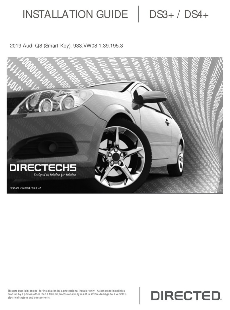
INSTALLATION GUIDE
This product is intended for installation by a professional installer only! Attempts to install this
product by a person other than a trained professional may result in severe damage to a vehicle’s
electrical system and components.
2017-06-21
© 2017 Directed, Vista CA
DS4+
Designed by Installers for Installers
Contents
Warning! Safety first ....................................................................................................................... 3
Introduction .................................................................................................................................... 4
Pre-installation and application warnings ..................................................................................... 4
Vehicle application guide........................................................................................................... 5
Wiring connections ......................................................................................................................... 6
Main harness (H1), 12-pin black connector .................................................................................. 6
Relay harness (H2), 10-pin white connector.................................................................................. 6
Data harness (H3), 8-pin white connector..................................................................................... 6
Analog input/output harness (H4), 22-pin white connector............................................................. 7
RF Port harness (H5), 2-pin white connector.................................................................................. 7
D2D harness (H6), 4-pin white (1) and black (2) connectors ........................................................... 7
Temperature sensor harness (H7), 2-pin black connector ................................................................ 7
Installation (wiring diagrams, fuse selection & vehicle wiring reference charts)........................................ 8
Type 1 with T-Harness (THHON3)................................................................................................ 8
Type 1 ..................................................................................................................................... 9
Type 2 with T-Harness (THHON2).............................................................................................. 12
Type 2 ................................................................................................................................... 13
Type 3 with T-Harness (THHON1).............................................................................................. 16
Type 3 ................................................................................................................................... 17
Type 4 with T-Harness (THHON1).............................................................................................. 19
Type 4 ................................................................................................................................... 20
Type 5 with T-Harness (THHON2).............................................................................................. 24
Type 5 ................................................................................................................................... 25
Type 6 ................................................................................................................................... 28
Type 7 ................................................................................................................................... 30
T-Harness modification procedure.................................................................................................... 32
Key2GO...................................................................................................................................... 32
Configuring the system................................................................................................................... 32
Important! .............................................................................................................................. 32
Vehicles equipped with a manual transmission............................................................................ 33
RF Systems ............................................................................................................................. 33
8504D Combo Sensor............................................................................................................. 33
When used in conjunction with SmartStart.................................................................................. 33
D2D port configuration ............................................................................................................ 33
Module programming.............................................................................................................. 34
LED diagnostics and troubleshooting.......................................................................................... 36
Soft reset................................................................................................................................ 38
Hard reset .............................................................................................................................. 38
Learning the Tach (not needed with Virtual Tach) ............................................................................... 39
Initializing Virtual Tach (not needed with hardwired or data tach applications) ..................................... 39
Limited lifetime consumer warranty .................................................................................................. 40
Quick Reference Guide.................................................................................................................. 41
3DS4+ HONDA7
© 2017-06-21 Directed. All rights reserved.
Warning! Safety first
The following safety warnings must be observed at all times:
• Due to the complexity of this system, installation of this product must only be performed by an authorized Directed dealer.
• When properly installed, this system can start the vehicle via a command signal from the remote control. Therefore, never
operate the system in an area that does not have adequate ventilation.
The following precautions are the sole responsibility of the user; however, authorized Directed dealers should:
• Never use a test light or logic probe when installing this unit. Always use a multimeter.
• Never operate the system in an enclosed or partially enclosed area without ventilation (such as a garage).
• USER MUST INSTALL A CARBON MONOXIDE DETECTOR IN OR ABOUT THE LIVING AREA ADJACENT TO THE VEHICLE.
ALL DOORS LEADING FROM ADJACENT LIVING AREAS TO THE ENCLOSED OR PARTIALLY ENCLOSED VEHICLE
STORAGE AREA MUST REMAIN CLOSED AT ALL TIMES.
Use of this product in a manner contrary to its intended mode of operation may result in property damage, personal injury, or
death. Except when performing the Safety Check outlined in this installation guide, (1) Never remotely start the vehicle with
the vehicle in gear, and (2) Never remotely start the vehicle with the keys in the ignition. The user is responsible for having the
neutral safety feature of the vehicle periodically checked, wherein the vehicle must not remotely start while the car is in gear.
This testing should be performed by an authorized Directed dealer in accordance with the Safety Check outlined in this product
installation guide. If the vehicle starts in gear, cease remote start operation immediately and consult with the user to fix the problem
immediately.
OPERATION OF THE REMOTE START MODULE IF THE VEHICLE STARTS IN GEAR IS CONTRARY TO ITS INTENDED MODE OF
OPERATION. OPERATING THE REMOTE START SYSTEM UNDER THESE CONDITIONS MAY RESULT IN PROPERTY DAMAGE
OR PERSONAL INJURY. IMMEDIATELY CEASE THE USE OF THE UNIT AND REPAIR OR DISCONNECT THE INSTALLED REMOTE
START MODULE. DIRECTED WILL NOT BE HELD RESPONSIBLE OR PAY FOR INSTALLATION OR REINSTALLATION COSTS.
Remote starters for manual transmission pose significant risks if not properly installed and operated. When testing to ensure the
installation is working properly, only remote start the vehicle in neutral gear, on a flat surface and with a functional, fully engaged
parking brake. Do not allow anyone to stand in front of or behind the vehicle.
This product should not be installed in any convertible vehicles, soft or hard top with a manual transmission. Installation in such
vehicles may pose certain risk.
4DS4+ HONDA7
© 2017-06-21 Directed. All rights reserved.
Introduction
The HONDA7 firmware for DS4+ is compatible with specific Acura and Honda vehicles. It is a complete
solution for remote start, security (when security features are enabled), bypass, and features built in Bluetooth
4.0 allowing you to configure and control your system. This guide provides information on the installation of
the module as an analog unit, however a digital solution could be available for your vehicle. Please refer to the
DirectLink application or www.directechs.com for more information about which configuration is best for your
application.
Warning! This module is designed to be configured using the DirectLink application for mobile devices, however it can also
be configured using the web tool located at www.directechs.com. To download the DirectLink mobile application, please visit the
Google Play or Apple store.
Pre-installation and application warnings
Firmware notes: This section highlights important information for this specific firmware and will assist in
pricing accordingly, as well as bringing awareness to any operational or vehicle limitations.
T-Harness
compatible THHON1, THHON2 & THHON3 Keys required for
programming 1Keys required for
operation 0
No takeover available on Push-to-Start vehicles. The engine will stop when a door is opened. Wait at least 2 seconds
before restarting the engine or an error message can appear in the vehicle information display.
Power liftgate and sliding door controls are only available when the engine is OFF.
The optional Plug & Play THHON1, THHON2 & THHON3 T-Harnesses are sold separately. Refer to the "Vehicle wiring
reference chart" for vehicle and T-Harness compatibilities. When using a T-Harness, the OEM remote functionality is retained
during remote start runtime.
Key2GO may be required if the interface does not program using the traditional method. Refer to "Module programming"
on page 34 for more information.
Unless specified otherwise, all connectors are displayed from the wire side, with the exception of the OBDII diagnostic
connector.
It is important to check that the fuses are positioned correctly in the module. Refer to the "Fuse selection" section following
each installation type for more information.
Refer to the "Vehicle wiring reference chart" following each installation type.
General notes: This section highlights important information for this specific firmware.
[1] The installation of an aftermarket hood pin is ONLY required on vehicles that are NOT equipped with a factory hood pin.
[2] The siren is ONLY required when enabling the security features during module flashing.
[3] The Green wire is ONLY required for starter disable and antigrind applications.
[4] Optional but required for OEM Remote Keyless Entry to operate when vehicle is remote started.
[5] PTS wire, for Pit Stop/Idle mode shutdown ONLY.
[6] For Autolights OFF CUT the Brown/White loop in all vehicles EXCEPT in the 2016 Honda Civic (Key Type) when using a
THHON3 T-Harness.
[7] When using a T-Harness and the OEM Remote Keyless Entry does NOT operate when vehicle is remote started, cut and
tape the White in pin 5 of the Black 12-pin harness. See "T-Harness modification procedure" on page 32.
Additional parts required (maximum required):
Diode 6A
0 x 1A Diodes 86 85
30
87a
87
0 x Relay
Resistor 100Ω
0 x Resistor
Fuse 7.5A
0 x Fuse
5DS4+ HONDA7
© 2017-06-21 Directed. All rights reserved.
Vehicle application guide
The following table lists the vehicles and features which are compatible with this product. The number assigned to each year
allows you to determine which installation type should be used for your vehicle.
Vehicles
2017
2016
2015
2014
2013
PK-Immobilizer Bypass-Data No Key Req'd
DL-Arm Factory Security
DL-Disarm Factory Security
DL-Door Lock Control
DL-Door Unlock
DL-Driver Priority Unlock
DL-Sliding Door Control Driver
DL-Sliding Door Control Passenger
DL-Trunk / Hatch Release
FOB-Control of aftermarket alarm with OEM
remote
Key2GO
RS-3x LOCK START (Start control using OEM
Remote)
RS-3x LOCK STOP (Stop control using OEM
Remote)
RS-RAP Shut Down (Retained ACC Power)
RS-SmartStart
RS-Tach / RPM Output
SS-Entry Monitoring ALL Door Pins
SS-Entry Monitoring Hood Pin
SS-Entry Monitoring Trunk/Hatch Pin
SS-Factory Alarm Trigger Monitoring
ST-Brake Status (foot brake)
ST-Door Locks Status
ST-E-Brake Status
ST-Ignition Status
Acura
ILX (Smart Key) 44 •••••• ••••••••••••••••
MDX (Smart Key) 4444 •••••• ••••••••••••••••
RDX (Smart Key) 44 •••••• ••••••••••••••••
RLX (Smart Key) 22 •••••• ••••••••••••••••
TLX (Smart Key) 444 •••••• ••••••••••••••••
Honda
Accord 11111•••••• ••••••••••••••••
Accord (Smart Key) 22222•••••• ••••••••••••••••
Accord Crosstour 1 1 1 • • • • • • • • • • • • • • • • • • • • • •
Accord Crosstour (Smart Key) 222•••••• ••••••••••••••••
Accord Hybrid (Smart Key) 2222 •••••• ••••••••••••••••
Civic 11 •••••• ••••••••••••••••
Civic (Smart Key) 6655 •••••• ••••••••••••••••
Civic Hybrid (Smart Key) 55 •••••• ••••••••••••••••
CR-V (Smart Key) 722 •••••• ••••••••••••••••
Fit 111 •••••• ••••••••••••••••
Fit (Smart Key) 333 •••••• ••••••••••••••••
HR-V 11 •••••• ••••••••••••••••
HR-V (Smart Key) 33 •••••• ••••••••••••••••
Odyssey (Smart Key) 4444 ••••••••••••••••••••••••
Pilot (Smart Key) 4 •••••• ••••••••••••••••
Ridgeline (Smart Key) 4 •••••• ••••••••• •••••
Legend:
DL: OE Door Lock & Alarm Controls
FOB: Sync CAN Interface w/ FOB Remote
PK: Transponder & Immobilizer Override
RS: Remote Start & Engine Controls
SS: Integrated Security & Monitoring
ST: Function/Feature Status
6DS4+ HONDA7
© 2017-06-21 Directed. All rights reserved.
Wiring connections
The wiring connections listed below are specific to this firmware.
Main harness (H1), 12-pin black connector
Conn./Pin Color Description
H1/1 Blue/White Relay 1 N.C. – Ignition Interrupt (vehicle side)
H1/2 Blue/Red Relay 1 N.O. – No Connection 1
H1/3 Blue Relay 1 COM – Ignition Interrupt (conn. side)
H1/4 White/Brown Relay 3 N.C. – No Connection 1
H1/5 White Relay 3 COM – (+) Accessory 1 Output 1
H1/6 Red (+) 12 Volt (Battery)
H1/7 Lt. Green/Red Relay 2 N.O. – (+) 12V (Battery) 1
H1/8 Lt. Green Relay 2 COM – (+) Ignition Output 1
H1/9 Lt. Green/White Relay 2 N.C. – No Connection 1
H1/10 Black (-) Ground
H1/11 White Relay 3 COM – (+) Accessory 1 Output 1
H1/12 Red (+) 12 Volt (Battery)
Relay harness (H2), 10-pin white connector
Conn./Pin Color Description
H2/1 N/A No Connection
H2/2 Red/Black (+) 12 Volt Input (Accessory/Starter)
H2/3 Pink/Black Relay N.C. – Flex 1
H2/4 Pink/White Relay COM – Flex Relay Output 1
H2/5 Red (+) 12 Volt (Battery) Input
H2/6 Green Relay COM – Starter Input (From Key Switch) 1
H2/7 Violet Relay N.C. – (+) Starter Output (To Starter) 1
H2/8 Orange Relay COM – (+) Accessory Output 1
H2/9 Red/White (+) Fused (30A) Ignition 2/Flex Relay Input
H2/10 Pink Relay COM – (+) Ignition Output
Data harness (H3), 8-pin white connector
Conn./Pin Color Description
H3/1 Tan HS CAN Low
H3/2 Tan/Black HS CAN High
H3/3 Orange/Brown FT CAN Low
H3/4 Orange/Green FT CAN High
H3/5 Lt. Green No Connection
H3/6 Violet/Brown No Connection
H3/7 Orange/Black No Connection
H3/8 Yellow/Black Immobilizer Data
1. If these outputs are not used by the firmware, they can be configured by the installer when the module is flashed.
7DS4+ HONDA7
© 2017-06-21 Directed. All rights reserved.
Analog input/output harness (H4), 22-pin white connector
Conn./Pin Color Description
H4/1 Lt. Green/Black (-) PTS Output 1
H4/2 Blue/White No Connection 1
H4/3 Dk. Green/Black (-) Lock Output1
H4/4 Red/White No Connection 1
H4/5 Brown/Black (-) Horn Output 1
H4/6 Brown/White N/A
H4/7 White (+) Accessory 2 Output 1
H4/8 Violet/Black (+) Starter Output 1
H4/9 Dk. Blue/Black (-) Unlock Output 1
H4/10 Lt. Blue/Black (-) Parking Lights Output 1
H4/11 Brown/Red (+) Siren Output 1
H4/12 Pink (+) Ignition Sense Input
H4/13 Violet (+) Door Input 2
H4/14 Brown (+) Brake Input 2
H4/15 White/Blue (-) Activation (Start Trigger) Input 2
H4/16 Blue/Red No Connection 2
H4/17 Black/White (-) Parking Brake Input (Manual Transmission) 2
H4/18 Orange/Black (-) Instant Alarm Trigger Input 2
H4/19 Blue (-) Trunk Trigger Input 2
H4/20 Green (-) Door Input 2
H4/21 Gray (-) Hood Input 2
H4/22 Violet/White (AC) Tach Input
RF Port harness (H5), 2-pin white connector
Conn./Pin Color Description
H5/1 N/A RF Loop
H5/2 N/A RF Loop
D2D harness (H6), 4-pin white (1) and black (2) connectors
Conn./Pin Color Description
H6/1 Blue (Data) TX
H6/2 Black (-) Ground
H6/3 Green (Data) RX
H6/4 Red (+) 12 Volt
Temperature sensor harness (H7), 2-pin black connector
Conn./Pin Color Description
H7/1 Black Temperature Sensor
H7/2 Black Temperature Sensor
1. If these outputs are not used by the firmware, they can be configured by the installer when the module is flashed. Note that they are low current and a relay
may be necessary.
2. These connections are only required if the corresponding statuses are not supported by the firmware. See "Vehicle application guide" on page 5 for a
list of compatible features. If these outputs are not used by the firmware, they can be configured by the installer when the module is flashed. Note that they
are low current and a relay may be necessary.
8DS4+ HONDA7
© 2017-06-21 Directed. All rights reserved.
Installation (wiring diagrams, fuse selection & vehicle wiring reference charts)
Type 1 with T-Harness (THHON3)
Refer to "Pre-installation and application warnings" on page 4 and "Vehicle wiring reference chart" on page 10 for important information on this installation.
Cut the Brown/White
loop in all vehicles
EXCEPT in the 2016
Honda Civic (Key Type).
T-Harness wiring NOT
shown in the diagram
is NOT used with this
installation type.
Cut
FT CAN High: Orange/Green
FT CAN Low: Orange/Brown
(-) Parking Lights Output: Lt. Blue/Black
(-) Parking Lights:
pin 8
123456
7
89101112
F-CAN High: pin 6
F-CAN Low: pin 14
OBDII
Diagnostic Conn.
16
8
9
1
Siren
Hood Pin
(-) Hood Input: Gray
(+) Siren Output: Brown/Red
Immobilizer Control Unit
(Gray conn. at immobilizer module)
Ignition Switch
(White connector at ignition switch)
8-pin
White
Connector
22-pin
White
Connector
12-pin
Black
Connector
10-pin
White
Connector
THHON3
(Optional T-Harness)
Headlight Switch
(White conn. at headlight switch)
22 810 12
4 2442
DS4+
DS4
Slide
to open
Proper Fuse
Positioning
DS4+ DS4
MAIN (5A) (+)
(-) RLY3 PK LIGHT (15A) (+)
(-) ACC & START (30A) (+)
(-) FLEX RLY (20A) (+)
IGN (20A) (+)
MAIN (5A) (+)
(-) RLY3/PK LIGHT(15A) (+)
5
5
It is important to check that the
fuses are positioned correctly.
30
20
20
9DS4+ HONDA7
© 2017-06-21 Directed. All rights reserved.
Type 1
Refer to "Pre-installation and application warnings" on page 4 and "Vehicle wiring reference chart" on page 10 for important information on this installation.
(+) 12V : Red: 6 & 12
12
534
Siren
Hood Pin
(-) Hood Input: Gray: 21
(+) Siren Output: Brown/Red: 11
(-) Parking Lights:
pin 8
123456
7
89101112
Immobilizer Data: Yellow/Black: 8
B-CAN High:
Pink, pin 4
B-CAN Low:
Blue, pin 5
Immo. Data:
pin 2
72
3
456 1
HS CAN Low: Tan : 1
HS CAN High: Tan/Black: 2
FT CAN High: Orange/Green: 4
F-CAN High: pin 6
F-CAN Low: pin 14
OBDII
Diagnostic Conn.
16
8
9
1
FT CAN Low: Orange/Brown: 3
(-) Parking Lights: Lt. Blue/Black: 10
(+) Starter Output (Vehicle side): Violet: 7
(+) Starter Intput (Key side): Green: 6
Ignition Interrupt (vehicle side): Blue/White: 1
Ignition Interrupt (conn. side): Blue: 3
(+) Ignition:
pin 2
(+) Acc.: pin 4
(+) Starter:
pin 5
(+) 12V: pin 1
(+) 12V Input: Red/Black: 2
(+) Accessory Output: Orange: 8
(+) 12V Input: Red: 5
(+) Ignition Input/Output: Pink: 10
(-) Ground: Black: 10
Ignition: pin 6
Cut
Ignition Switch
(White conn.
at ignition switch)
Headlight Switch
(White conn. at headlight switch)
Immobilizer Control Unit
(Gray connector at immobilizer module)
22 810 12
4 2442
DS4+
DS4
Slide
to open
Proper Fuse
Positioning
DS4+ DS4
MAIN (5A) (+)
(-) RLY3 PK LIGHT (15A) (+)
(-) ACC & START (30A) (+)
(-) FLEX RLY (20A) (+)
IGN (20A) (+)
MAIN (5A) (+)
(-) RLY3/PK LIGHT(15A) (+)
5
5
It is important to check that the
fuses are positioned correctly.
30
20
20
10 DS4+ HONDA7
© 2017-06-21 Directed. All rights reserved.
Vehicle wiring reference chart
This section provides vehicle wiring information to guide you through the various stages of your installation. Refer to
www.directechs.com for additional information.
Wire Information Connector Information
Function Color Pin Polarity Location Color Pins Ref.
Honda Accord 2013-2017
Accessory Orange 4 (+) Ignition switch. White 5 A
Ignition Green 2 (+) Ignition switch. White 5 A
12V White 1 (+) Ignition switch. White 5 A
Starter Blue 5 (+) Ignition switch. White 5 A
B-CAN High Pink 4 Data Immobilizer Control Unit right of steering column under ignition switch. Gray 7 B
B-CAN Low Blue 5 Data Immobilizer Control Unit right of steering column under ignition switch. Gray 7 B
Ignition Interrupt Brown 6 Cut Immobilizer Control Unit right of steering column under ignition switch. Gray 7 B
Immo Data Gray 2 Data Immobilizer Control Unit right of steering column under ignition switch. Gray 7 B
Parking Lights Gray 8 (-) Headlight switch. White 12 C
F-CAN High White 6 Data OBDII. White 16 D
F-CAN Low Red 14 Data OBDII. White 16 D
Honda Accord Crosstour 2013-2015
Accessory Orange 4 (+) Ignition switch. White 5 A
Ignition Blue 2 (+) Ignition switch. White 5 A
12V White 1 (+) Ignition switch. White 5 A
Starter Yellow 5 (+) Ignition switch. White 5 A
B-CAN High Pink 4 Data Immobilizer Control Unit right of steering column under ignition switch. Gray 7 B
B-CAN Low Blue 5 Data Immobilizer Control Unit right of steering column under ignition switch. Gray 7 B
Ignition Interrupt Yellow 6 Cut Immobilizer Control Unit right of steering column under ignition switch. Gray 7 B
Immo Data Lt. Green 2 Data Immobilizer Control Unit right of steering column under ignition switch. Gray 7 B
Parking Lights Gray 8 (-) Headlight switch. White 12 C
F-CAN High White 6 Data OBDII. White 16 D
F-CAN Low Red 14 Data OBDII. White 16 D