2
PIP-IP1758
AVVERTENZE GENERALI PER LA SICUREZZA
Il presente manuale di installazione è rivolto esclusivamente a per-
sonale professionalmente competente. Leggere attentamente le
istruzioni prima di iniziare l’installazione del prodotto. I materiali dell’imballag-
gio (plastica, polistirolo, ecc.) non vanno dispersi nell’ambiente e non devono
essere lasciati alla portata dei bambini in quanto potenziali fonti di pericolo.
Prima di iniziare l’installazione verificare l’integrità del prodotto. Per l’eventua-
le riparazione o sostituzione dei prodotti dovranno essere utilizzati esclusiva-
mente ricambi originali.
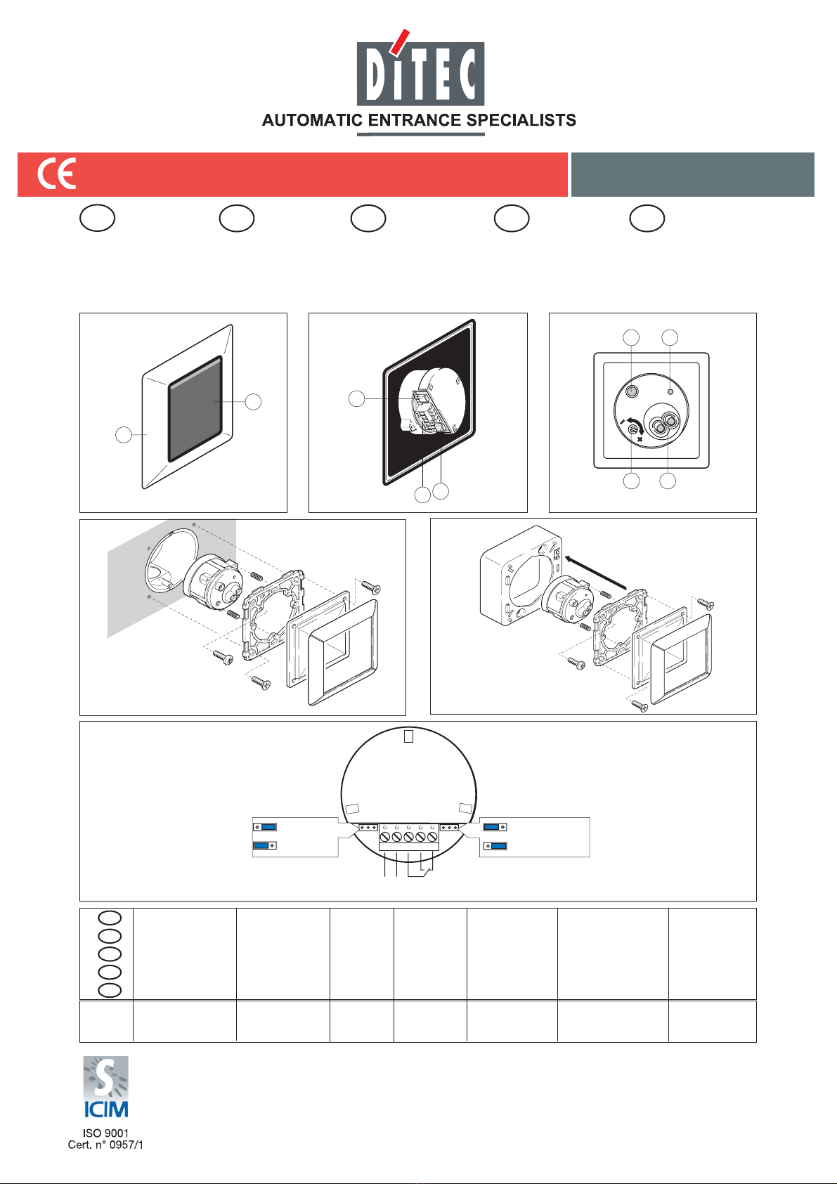
1. Riferimenti (Fig. 1-2-3)
[1] Mascherina [6] Regolatore sensibilità
[2] Lente [7] Trasmettitore
[3] Jumper selezione portata [8] Ricevitore
[4] Morsettiera [9] Ledsegnalazionefunzionamento
[5] Jumper modalità rilevamento
2. Installazione
(Fig. 4) Montaggio in scatola da incasso a muro.
(Fig. 5) Montaggio con scatola da esterno.
Importante: all’accensione, evitare di collocare oggetti nell’area di
rilevamento.
3. Collegamenti elettrici
Effettuare i collegamenti indicati in fig. 6.
4. Regolazioni (fig. 6)
Con il jumper EN regolare la portata (50-200 mm / 50-600 mm).
Con il jumper TS impostare lo stato del contatto (impulsivo/passo-
passo).
Con il trimmer [6] regolare la sensibilità di rilevazione.
Attenzione: dopo aver effettuato i collegamenti elettrici e
le regolazioni necessarie, chiudere il PID e togliere
alimentazione per ca. 5 s quindi riaccendere il sensore.
GENERALSAFETY PRECAUTIONS
This installation manual is intended for professionally competent
personnel only. Read the instructions carefully before beginning to
install the product. Incorrect installation may be a source of danger.
Packaging materials (plastic, polystyrene, etc.) must not be allowed to litter
the environment and must be kept out of the reach of children for whom they
may be a source of danger. For repairs or replacements of product only
original spare parts must be used.
1. Reference (Fig. 1-2-3)
[1] Cover frame [6] Sensitivity adjuster
[2] Lens [7] Transmitter
[3] Range selection jumper [8] Receiver
[4] Connection terminal [9] Function selection LED
[5] Detection area mode jumper
2. Installation
(Fig. 4) Flush mounted connector box
(Fig. 5) External connector box
Important: When you connect the device, no objects may be in
the detection area.
3. Electrical connection
Connect as show in fig. 6.
4. Adjustment (fig. 6)
With jumper EN adjust the range (50-200 mm / 50-600 mm).
With jumper TS adjust the output mode (impulsive/switch ON-OFF).
With trimmer [6] adjust the sensitivity.
Attention: after the electrical connection and the neces-
sary adjustments, close PID and switch OFF power supply
for about 5 s then switch ON the sensor.
CONSIGNES GENERALES DE SECURITE
Cette notice d’installation est destinée exclusivement aux profes-
sionnels qualifiés. Lire attentivement les instructions avant de pro-
céder à l’installation du produit. Une installation erronée peut être source de
danger. Les materiaux d’emballage (plastique, polystyréne, etc ne doivent
pas être abandonnés dand la nature et ne doivent pas être laissés à la portée
des enfants, car ils sont une source potentielle de danger.En cas de répara-
tion ou de remplacement des produits, les piéces de rechange originales
doivént impérativement être utilisées.
1. Eléments
[1] Support [6] Régulateur de sensibilité
[2] Lentille [7] Emetteur
[3] Cavalier portées de détection [8] Récepteur
[4] Borne de connexion [9] Led indicateur de fonction
[5] Cavalier mode de détection
2. Installation
(Fig. 4) Assemblage en boîte de dérivation encastrable
(Fig. 5) Assemblage en boîte de dérivation externe
Important: aucun objet ne doit se trouver dans le champ de
détection au moment de connecter le radar.
3. Raccordements électriques
Effectuer les raccordements indiqués dans la fig 6.
4. Réglage (fig. 6)
Avec cavalier EN regler la portée (50-200 mm / 50-600 mm).
Avec le jumper (cavalier) TS programmer l’état du contact (par
impulsions/pas à pas).
Avec trimmer [6] regler la sensibilité de détection.
Attention: Aprés raccordements électriques et le réglage
nécessaire, enfermer le PID et couper l’alimentation pen-
dant ca. 5 s donc rallumer le radar.
ALLGEMEINE SICHERHEITSHINWEISE
Das vorliegende Installationshandbuch ist ausschliesslich für Fach-
personal bestimmt.
Vor Einbaubeginn sind die Anweisungen sorgfältig durchzulesen. Falscher
Einbau kann Gefahr mit sich bringen.
Das Verpackunsmaterial (Kunststoff, Polystyrol, usw.) ist vorschriftsmäßig
zu entsorgen. Es ist von Kindern fernzuhalten, da es eine Gefahr für sie
bedeutet. Vor Beginn der Montage ist der einwandfreie Zustand des Produkts
zu überprüfen. Bei Reparatur und Austausch sind ausschliesslich Originaler-
satzteile zu verwenden.
1. Verweise (Abb. 1-2-3)
[1] Frontrahmen [6] Empfindlichkeits-einstellung
[2] Linse [7] Sender
[3] Jumper Reichweiteneinstellung [8] Empfänger
[4] Anschlußklemmen [9] LED Funktionsanzeige
[5] Jumper für Erfassungsfunktion
2. Montage
(Abb. 4) Montage in Unterputz-Abzweigdose
(Abb. 5) Montage in externe Abzweigdose
Wichtig: BeimAnschliessen des Gerätes an die Betriebsspannung,
darf kein Objekt im Detektionsbereich sein.
3. Elektrische Anschlüsse
Anschlüsse gemäß Abb. 6 durchführen.
4. Einstellungen (Abb. 6)
Mit Jumper EN stellen Sie die Reichtweite ein (50-200 mm / 50-600
mm).
Mit dem TS Jumper die Einstellung des Kontakts (Steuerimpuls/
Schrittbetrieb) vornehmen.
Mit Trimmer [6] stellen Sie die Empfindlichkeit ein.
Achtung: Nach erfolgtem elektrischen Anschluß und
Einstellung, PID schließen und die Betriebsspannung für
ca. 5 s ausschalten und dann wieder einschalten.
ADVERTENCIASGENERALESDE SEGURIDAD
El presente manual de instalaciòn està destinado exclusivamente a
professionalescalificados.Leeratentamentelasinstruccionesantes
de comenzar la instalaciòn del producto. El material de embalaje (plàstico,
poliestirol, etc.) debe desecharse sin causar daño al medio ambiente y
mantenerse fuera del alcance de los niños, porque es una potencial fuente de
peligro. Antes de comenzar la instalaciòn verificar que el producto esté
integro. Para cualquier reparaciòn o sustituciòn del producto, utilizar
exclusivamente repuestos originales.
1. Elementos (Fig. 1-2-3)
[1] Marco frontal [6] Trimmerregulaciònsensibilidad
[2] Lente [7] Transmisor
[3] Puente seleciòn alcance [8] Receptor
[4] Borne de conexiòn [9] Ledindicadordefuncionamiento
[5] Puente modo de detecciòn
2. Instalaciòn
(Fig. 4) Montaje en caja de derivación empotrable.
(Fig. 5) Montaje en caja de derivación externa.
Importante: all’encendido, ningùn objeto debe encontrarse en el
àrea de detecciòn.
3. Conexiones eléctricas
Efectuar las conexiones indicadas en la fig. 6.
4. Regulación (fig. 6)
Con puente EN ajustar el alcance (50-200 mm / 50-600 mm).
Con el jumper TS configurar el estado del contacto (Impulsivo/
paso-paso).
Con trimmer [6] ajustar la sensibilidad de detecciòn.
Atenciòn: después de los conexiones eléctricas y los
regulaciònes, cerrar el PID y desconectar la corriente aprox.
5 seg. y vuelva a conectarla de nuevo.
I
GB
F
D
E