DKS 1600 Series User manual

Supplemental Instructions for Series 1600, 6000, 9000
Vehicular Gate Operators with Battery Backup
DoorKing, Inc.
120 Glasgow Avenue
Inglewood, California 90301
U.S.A.
Phone: 310-645-0023
Fax: 310-641-1586
www.doorking.com
Owner’s Manual
P/N 2340-065 REV F, 4/04
Copyright 2001 DoorKing, Inc. All rights reserved.

Page 2

Page 3
Use this manual as a supplement to and with the
manuals included in the following models
1601, 1602 Barrier Gate Operators, 6100, 6300 Swing Gate Operators, 9150, 9300, 9310 Slide
Gate Operators.
DoorKing, Inc. reserves the right to make changes in the products described in this manual
without notice and without obligation of DoorKing, Inc. to notify any persons of any such revisions
or changes. Additionally, DoorKing, Inc. makes no representations or warranties with respect to
this manual. This manual is copyrighted, all rights reserved. No portion of this manual may be
copied, reproduced, translated, or reduced to any electronic medium without prior written consent
from DoorKing, Inc.

IMPORTANT NOTICES
This manual is used as a supplement to the installation instructions that are provided with the
vehicular gate operator. This manual references only the battery backup system and its connections
to the vehicular gate operator. Refer to the operator installation manual for all other instructions.
The optional battery backup system installed in your vehicular gate operator is designed as a
convenience enhancement only. It is not designed or intended to provide continuous gate operation
during a power outage. Its sole purpose is to provide a method to open the vehicular gate to allow
unimpeded traffic flow when the gate and access control system is without power.
If your access control system requires 100% power backup and continuous operation when primary
(AC) power has failed, a power inverter / backup system, such as DoorKing’s Model 2000, is
required.
•The battery backup system cannot provide continuous gate operation during a power outage.
•Operation of this system is limited to cycling the gate to the open (up) position one time only.
•The battery backup system requires testing on a monthly basis to insure the batteries are
fully charged and that the system is operational.
•The battery backup system uses two 12-volt, 3.0 amp-hour gel-cell batteries. These batteries
should be replaced every two years on average, or sooner if required.
•Batteries are affected by temperature. Cold temperatures will reduce the effectiveness of the
batteries and the backup system. High temperatures will result in a shortened battery life.
•Batteries are not covered under warranty.
Page 4

1.1 OPERATING MODES
This battery backup system consist of a control board (2340-010), motor and power supply (batteries)
providing a completely redundant drive system to open the gate should a power outage occur. This
backup system is not designed to maintain continuous gate operation; rather it provides a convenient
method to open a gate during adverse conditions. If continuous gate and access control system
operation is required, refer to the DoorKing Model 2000 Inverter / Backup Power System.
When installed in slide or swing gate operators, the backup system can be set to operate in either a
manual (for residential applications) or automatic (for apartment complexes, gated communities, etc.)
mode of operation. The system will only operate in automatic mode when installed in a barrier gate
operator.
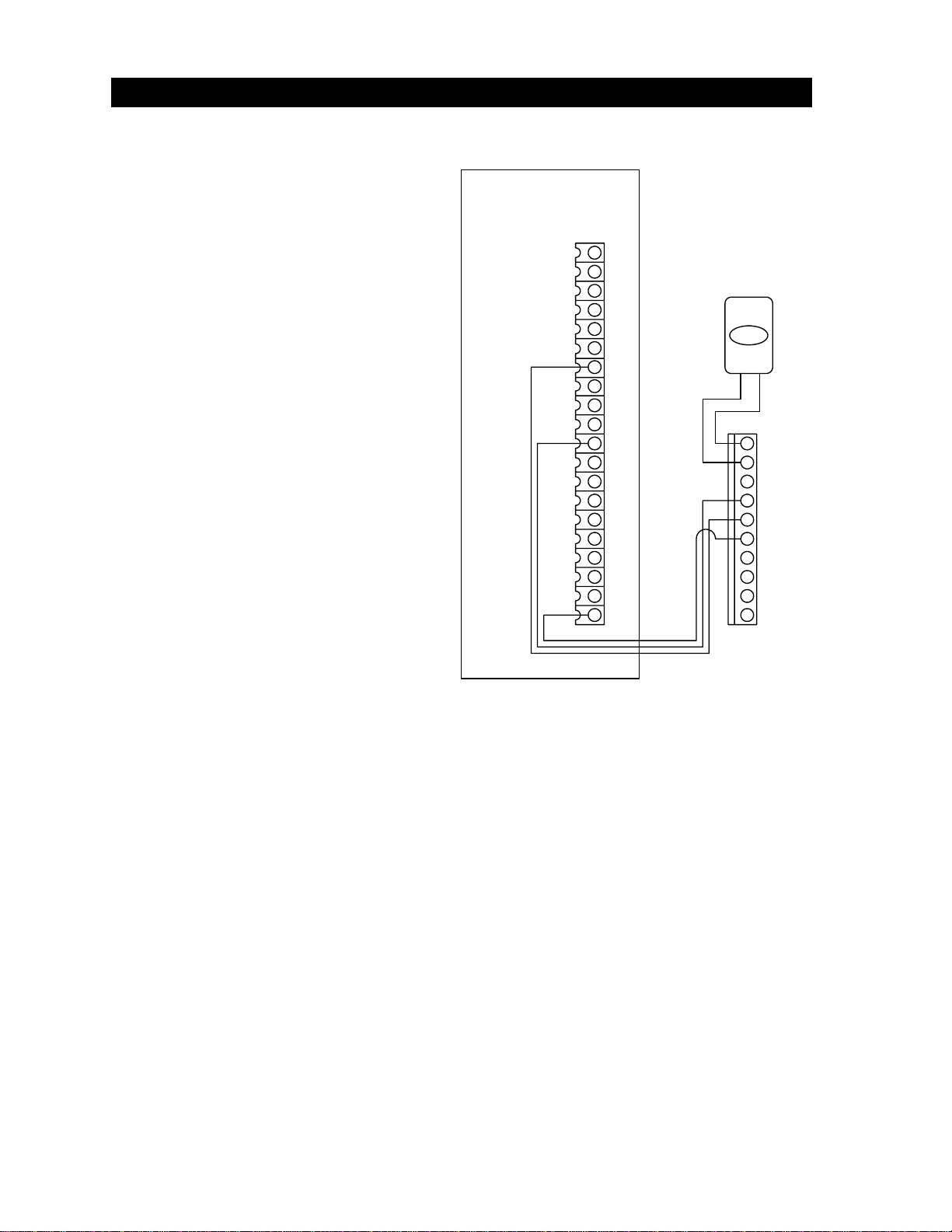
Manual Open (slide, swing gates only) – Residential Only
Manual mode is designed for residential applications only. In manual mode (switch 1 OFF), the
battery backup system will not open the gate if a power failure occurs until a manual input, either from
a wired push button or RF transmitter, is received. This allows the gate to remain closed upon a loss
of AC power, but provides a method to open the gate when desired. In manual mode of operation,
the RF receiver is connected directly to the battery backup control board and is powered by this board
(see page 18). During normal operation, when the relay in the radio receiver closes (a valid
transmitter code has been received), this “signal” is passed through the backup system control board
through terminal 4 and is feed directly to the gate operator main control board open input. If a power
failure occurs, the radio receiver is powered from the batteries maintaining its operation. When a
valid RF transmitter code is received under these conditions, the backup control board signals the DC
motor to start and the motor will run for the set run time. A switch closure (push button) across
terminals 1 and 2 on the backup control board will have the same result.
NOTE: The RF transmitter will open the gate provided that a stand-alone type receiver is in use. If
the gate system uses a receiver that outputs the transmitter code in weigand format to an access
controller (such as DoorKing models 1833, 1835, 1837 or 1838), then opening the gate from the RF
transmitter under power outage conditions will not be possible with this system.
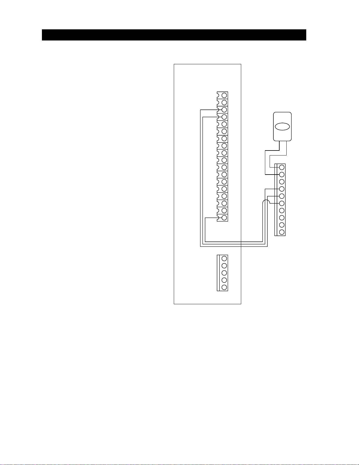
Automatic Open – Apartment Complexes, Gated Communities, Etc.
In automatic mode (switch 1 ON), the battery backup system will automatically open the gate or raise
the barrier arm approximately 2-3 seconds after a loss of AC power. Automatic mode is always used
for gates in general access applications such as gated communities, apartment complexes, etc.
Automatic mode must be used when the system is installed in barrier gate operators.
Automatic Restart
Once AC power is restored, the battery backup board can be set to automatically “re-key” the gate
operator (switch 3 ON) to establish normal operation, or can be set to require an input (switch 3 OFF)
before the gate operator resumes normal operation.
Page 5

1.2 ADJUSTMENTS
The DIP-switch located on the battery backup circuit board is used to setup the backup system for the
type of operator it is installed in, and to program how the backup system will respond when a power
outage occurs.
SWITCH FUNCTION SETTING DESCRIPTION
1 Operation OFF
ON
Residential applications. Gate will remain closed when a power
outage occurs. A radio receiver input or switch closure across
terminals 1 and 2 will cause the gate to run to the open position.
Apartment complexes, gated communities, etc. Gate will
automatically open when a power outage occurs. Switch must be
ON for 1601, 1602 barrier gate operators.
2 Direction OFF
ON Set so that the gate runs to the open (up) direction upon loss of AC
power.
3 Automatic
Power-up
Activation
OFF
ON
When AC power is restored, an input (push button, loop, radio
receiver, etc.) is required to return the gate to normal operation.
When AC power is restored, a 1-second pulse is sent to the gate
operator input to automatically restore normal operation.
4 Operator
Type OFF
ON
Slide and swing gate operators only.
1601, 1602 and 9310 operators only.
5 NOT USED OFF
6 NOT USED OFF
7 NOT USED OFF
8 NOT USED OFF
1 2 3 4 5 6 7 8
1
2
10
9
8
7
6
5
4
3
1 2 3 4 5 6 7 8
RUN TIMER
The run timer (see next page) sets the amount of time that the DC motor will run after it is activated
from the backup system circuit board. Adjust the run timer so that the gate opens to approximately
six inches of the full open position and then shuts off. Do not allow the DC motor to run long
enough to slip the operator clutch or stall the DC motor. Damage to the circuit board may
result from this condition. Clockwise increases the run time, counter-clockwise decreases the run
time.
NOTE: The run timer is not used when the backup system is installed in the 1601 or 1602
barrier gate operators.
Page 6

1.3 TERMINAL DESCRIPTION
1. COMMON
Common terminal for open input and radio receiver connected to the backup board.
Note: Radio receiver cannot be connected when the system is installed in a
1601 or 1602 barrier gate operator.
2. OPEN INPUT
Input from push button or radio receiver (slide and swing operators only) will activate
the gate operator.
3. RADIO POWER
24 -Volt power for radio receiver (slide and swing gate operators only).
4. ACTIVATION OUTPUT
Radio relay activation or switch closure across terminals 1 and 2 will send an
activation signal out of this terminal to the gate operator single-button activation input.
5. 24 VAC INPUT
6. 24 VAC COMMON
7. BATTERY POSITIVE INPUT
8. BATTERY NEGATIVE INPUT
9. DC MOTOR POSITIVE OUTPUT
10. DC MOTOR NEGATIVE OUTPUT
1 2 3 4 5 6 7 8
1
2
10
9
8
7
6
5
4
3
CHARGE
Led
MOTOR
RUN INCREASE
FACTORY
ADJUSTMENT ONLY!
FACTORY
ADJUSTMENT ONLY!
2340-010
Page 7

2.1 SWING GATE OPERATORS
2.1.1 SINGLE OPERATOR
•For general access applications, be
sure that the auto-open feature is
turned on. Set switch 1 to the ON
position.
1
2
3
4
5
6
7
8
9
10
11
12
13
14
15
16
17
18
19
20
1
2
3
4
5
6
7
8
9
10
MASTER - 4502 BOARD
OPEN
RED
GREEN
WHITE
2340 BACKUP CONTROL BOARD
•Connect a normally open push-button
to terminals 1-2 on the battery backup
control board. This allows another
method to open the gate when a
power outage occurs if the auto-open
feature is not used.
•Do not power any other devices from
the battery backup control board. All
other gate activating devices (card
readers, keypads, telephone entry,
etc.) should be connected to the gate
operator terminal strip as indicated in
the operator installation manual.
•Emergency vehicle access device
outputs should be connected to
terminals 1-2 on the battery backup
control board. This will enable
emergency vehicle access provided
that the emergency access device has
its own backup power supply and is
operational.
Figure 1
Page 8

2.1.2 MASTER / SLAVE OPERATORS
1
2
3
4
5
6
7
8
9
10
11
12
13
14
15
16
17
18
19
20
1
2
3
4
5
6
7
8
9
10
MASTER - 4502 BOARD
1
2
3
4
5
6
7
8
9
10
11
12
13
14
15
16
17
18
19
20
1
2
3
4
5
6
7
8
9
10
SWING GATE SLAVE
SLAVE MTR
OPEN
MASTER / SLAVE CONDUIT
RED
BLUE
WHITE
VIOLET
YELLOW
BROWN
ORANGE
GRAY
WHITE
VIOLET
YELLOW
BROWN
ORANGE
GRAY
RED
BLUE
2340 BACKUP CONTROL BOARD
Figure 2
•Wire swing gate master / slave operators as shown in Figure 2. Color code shown assumes
the use of DoorKing master / slave cable. Order part number 2600-755 (30 ft.), 2600-756 (40
ft.), 2600-757 (50 ft.).
•Place a jumper wire from terminal 19 to terminal 20 in the slave operator only.
•The gray wire that connects battery backup terminals 2 to each other is not required if the
auto-open feature is turned on.
•See swing gate operator installation manual for connection of secondary entrapment
protection devices.
Page 9

2.2 MODEL 9150 SLIDE GATE OPERATORS
2.2.1 SINGLE OPERATORS
•For general access applications, be
sure that the auto-open feature is
turned on. Set switch 1 to the ON
position.
1
2
3
4
5
6
7
8
9
10
11
12
13
14
15
16
17
18
1
2
3
4
5
6
7
8
9
10
SLIDE GATE MASTER
4602 BOARD
OPEN
RED
GREEN
WHITE
2340 BACKUP CONTROL BOARD
•Connect a normally open push-button
to terminals 1-2 on the battery backup
control board. This allows another
method to open the gate when a
power outage occurs if the auto-open
feature is not used.
•Do not power any other devices from
the battery backup control board. All
other gate activating devices (card
readers, keypads, telephone entry,
etc.) should be connected to the gate
operator terminal strip as indicated in
the operator installation manual.
•Emergency vehicle access device
outputs should be connected to
terminals 1-2 on the battery backup
control board. This will enable
emergency vehicle access provided
that the emergency access device has
its own backup power supply and is
operational.
Figure 3
Page 10

2.2.2 MASTER / SLAVE OPERATORS
1
2
3
4
5
6
7
8
9
10
11
12
13
14
15
16
17
18
1
2
3
4
5
6
7
8
9
10
SLIDE GATE MASTER
4602 BOARD
1
2
3
4
5
6
7
8
9
10
11
12
13
14
15
16
17
18
1
2
3
4
5
6
7
8
9
10
SLIDE GATE MASTER
4602 BOARD
OPEN
MASTER / SLAVE CONDUIT
VIOLET
YELLOW
BROWN
ORANGE
GRAY
VIOLET
YELLOW
BROWN
ORANGE
GRAY
1
2
3
4
5
RED
BLUE
WHITE WHITE
RED
BLUE
2340 BACKUP CONTROL BOARD
NOTE NOTE
Figure 4
•Slide gate systems use two master operators rather than a master-slave combination to
create bi-parting slide gates. Wire slide gate master / master operators as shown in Figure 4.
Color code shown assumes the use of DoorKing master / slave cable. Order part number
2600-755 (30 ft.), 2600-756 (40 ft.), 2600-757 (50 ft.).
•Be sure to connect the auxiliary terminals on the 4602 board as shown (gray, white, blue, red
wires). This assures that activation of a secondary entrapment device will stop or reverse
both gates.
•See slide gate operator installation manual for connection of secondary entrapment
protection devices.
•NOTE: If the battery backup system auto-open feature is not used, an additional wire
will need to be run in the master-slave conduit. With this wire, connect terminal 2 on
the battery backup circuit boards to each other.
Page 11

2.3 MODEL 9300 SLIDE GATE OPERATORS
2.3.1 SINGLE OPERATORS
•For general access applications, be
sure that the auto-open feature is
turned on. Set switch 1 to the ON
position
1
2
3
4
5
6
7
8
9
10
11
12
13
14
15
16
17
18
19
20
1
2
3
4
5
6
7
8
9
10
SLIDE GATE MASTER
4402 BOARD
OPEN
2340 BACKUP CONTROL BOARD
1
2
3
4
5
6
•Connect a normally open push-button
to terminals 1-2 on the battery backup
control board. This allows another
method to open the gate when a
power outage occurs if the auto-open
feature is not used.
•Do not power any other devices from
the battery backup control board. All
other gate activating devices (card
readers, keypads, telephone entry,
etc.) should be connected to the gate
operator terminal strip as indicated in
the operator installation manual.
•Emergency vehicle access device
outputs should be connected to
terminals 1-2 on the battery backup
control board. This will enable
emergency vehicle access provided
that the emergency access device has
its own backup power supply and is
operational.
Figure 5
Page 12

2.3.2 MASTER / SLAVE OPERATORS
1
2
3
4
5
6
7
8
9
10
11
12
13
14
15
16
17
18
19
20
1
2
3
4
5
6
7
8
9
10
SLIDE GATE MASTER
4402 BOARD
1
2
3
4
5
6
7
8
9
10
11
12
13
14
15
16
17
18
19
20
1
2
3
4
5
6
7
8
9
10
SLIDE GATE MASTER
4402 BOARD
OPEN
MASTER / SLAVE CONDUIT
1
2
3
4
5
6
2340 BACKUP CONTROL BOARD
1
2
3
4
5
6
Figure 6
•Slide gate systems use two master operators rather than a master-slave combination to
create bi-parting slide gates. Wire slide gate master / master operators as shown in Figure 6.
Color code shown assumes the use of DoorKing master / slave cable. Order part number
2600-755 (30 ft.), 2600-756 (40 ft.), 2600-757 (50 ft.).
•Be sure to connect the auxiliary terminal (CLS PHOTO) on the 4402 board as shown). This
assures that activation of a secondary entrapment device will stop or reverse both gates.
•See slide gate operator installation manual for connection of secondary entrapment
protection devices.
•NOTE: If the battery backup system auto-open feature is not used, an additional wire
will need to be run in the master-slave conduit. With this wire, connect terminal 2 on
the battery backup circuit boards to each other.
Page 13

2.4 MODEL 9310 SLIDE GATE OPERATORS
2.4.1 SINGLE OPERATORS SLIDE GATE MASTER
4403 BOARD
OPEN
2340 Backup Control Board
White
Green
Red
1
3
4
2
6
5
Main Terminal Strip
Aux Terminal Strip
Wire Assembly P/N 7082-305
Connects to “open” limit. Terminal
is dependent on mounting position
(left/right) of the operator.
1
4
3
2
6
7
5
8
9
10
Limit
Limit
Mid-Limit
Common
Common
12
13
11
15
16
14
19
20
17
18
1
2
4
3
7
6
5
10
9
8
•For general access applications, be sure
that the auto-open feature is turned on.
Set switch 1 and 4 to the ON position.
•Connect a normally open push-button to
terminals 1-2 on the battery backup
control board. This allows another method
to open the gate when a power outage
occurs if the auto-open feature is not
used.
•Do not power any other devices from the
battery backup control board. All other
gate activating devices (card readers,
keypads, telephone entry, etc.) should be
connected to the gate operator terminal
strip as indicated in the operator
installation manual.
•Emergency vehicle access device outputs
should be connected to terminals 1-2 on
the battery backup control board. This will
enable emergency vehicle access
provided that the emergency access
device has its own backup power supply
and is operational.
Figure 7
Page 14

2.4.2 MASTER / SLAVE OPERATORS
SLIDE GATE MASTER
4403 BOARD SLIDE GATE MASTER
4403 BOARD
OPEN
MASTER / SLAVE CONDUIT
2340 Backup Control Board
Yellow
Brown
Orange
Gray Gray
Yellow
Brown
Orange
1
3
4
2
6
5
1
4
3
2
6
7
5
8
9
10
Limit
Limit
Mid-Limit
Common
Common
12
13
11
15
16
14
19
20
17
18
1
2
4
3
7
6
5
10
9
8
1
2
3
4
6
5
1
2
3
4
6
5
8
7
9
10
16
17
19
20
18
10
11
13
14
12
15
5
6
7
8
9
1
3
4
2
Limit
Limit
Mid-Limit
Common
Common
Figure 8
•Slide gate systems use two master operators rather than a master-slave combination to
create bi-parting slide gates. Wire slide gate master / master operators as shown in Figure 6.
Color code shown assumes the use of DoorKing master / slave cable. Order part number
2600-755 (30 ft.), 2600-756 (40 ft.), 2600-757 (50 ft.).
•Be sure to connect the auxiliary terminal (CLS PHOTO) on the 4403 board as shown). This
assures that activation of a secondary entrapment device will stop or reverse both gates.
•See slide gate operator installation manual for connection of secondary entrapment
protection devices.
•NOTE: If the battery backup system auto-open feature is not used, an additional wire
will need to be run in the master-slave conduit. With this wire, connect terminal 2 on
the battery backup circuit boards to each other.
Page 15

2.5 BARRIER GATE OPERATORS
2.5.1 SINGLE OPERATORS
•The auto-open feature must be turned on
when the battery backup system is used in
the 1601 or 1602 barrier gate operators.
Be sure switch 1 is in the ON position.
1
2
3
4
5
6
7
8
9
10
11
12
13
14
1
2
3
4
5
6
7
8
9
10
BARRIER GATE MASTER
1601 BOARD
RED
GREEN
WHITE
2340 BACKUP CONTROL BOARD
•Switch 4 must be in the ON position.
This causes the battery backup circuit
board to look for the up magnetic limit
switch installed in the operator.
•When a power outage occurs, the barrier
arm will automatically raise to the up
position.
Figure 9
Page 16

2.5.2 MASTER / SLAVE OPERATORS
1
2
3
4
5
6
7
8
9
10
11
12
13
14
1
2
3
4
5
6
7
8
9
10
BARRIER GATE MASTER
1601 BOARD
2340 BACKUP CONTROL BOARD
1
2
3
4
5
6
7
8
9
10
11
12
13
14
BARRIER GATE MASTER
1601 BOARD
2340 BACKUP CONTROL BOARD
1
2
3
4
5
6
7
8
9
10
MASTER / SLAVE CONDUIT
YELLOW YELLOW
BROWN BROWN
ORANGE ORANGE
GRAY GRAY
Figure 10
•Barrier gate systems use two master operators rather than a master-slave combination to
create bi-parting barrier gates. Wire barrier gate master / master operators as shown in
Figure 8. Color code shown assumes the use of DoorKing master / slave cable. Order part
number 2600-755 (30 ft.), 2600-756 (40 ft.), 2600-757 (50 ft.).
Page 17

2.6 RESIDENTIAL APPLICATIONS
Battery backup systems used in residential applications may use an RF receiver to open the gate
upon a power outage rather than the auto-open feature that is used in general access applications.
This allows the residential gate to remain closed until it receives a command to open from the radio
receiver. To disable the auto-open feature, set switch 1 to the OFF position.
•If RF transmitters are used to open the access gate, connect the radio receiver to terminals
1-2-3 on the battery backup control board as shown in Figure 9. Terminal-1 is RADIO
RECEIVER COMMON, Terminal-2 is the RELAY CONTACT, terminal-3 is RADIO
RECEIVER POWER.
•Connecting the radio receiver in this manner allows the receiver to be powered from the
battery backup system during power outages. This will permit a transmitter to open the gate
during a power outage if the auto-open feature is not used.
•If your gate access system uses an RF receiver that outputs the received transmitter data in
weigand format to an external weigand controller, then the transmitter will not open the gate
unless the weigand controller has its own backup power system to provide it with backup
power when primary (AC) power fails.
1 2 3 4 5 6 7 8
1
2
10
9
8
7
6
5
4
3
COMMON
RELAY
POWER
RF REC’VR
Figure 11
Page 18

3.1 WIRING DIAGRAM
1
2
3
4
5
6
7
8
9
10
--++
RED
BLACK
BROWN
WHITE/BLACK
COMMON
24 VAC MONITOR
ACTIVATION OUTPUT
GREEN
RED
WHITE
2340-010 BATTERY BACKUP
CONTROL BOARD
ON / OFF
DC MOTOR
1601, 1602 Operators Only
REED SWITCH
MAGNET
N.O.
OPEN LIMIT SWITCH
9310 Operators Only 7082-305 Wire Assembly
BROWN
BLACK
Figure 12
Part Number Qty Description
2340-010 1 Control Board
1801-009 2 Battery, 12 Volt, 3.0 Amp Hour
1601-041 1 Toggle Switch
2600-196 1 DC Motor Assembly
1601-253 1 Reed Switch, Barrier Operators Only
2600-817 1 Magnet, Barrier Operators Only
7082-305 1 Wire Assembly – 9310 Operators Only
2600-688 1 V-Belt (Not Shown)
Page 19
This manual suits for next models
2
Table of contents
Other DKS Gate Opener manuals
Popular Gate Opener manuals by other brands

Casit
Casit MR33/CR63 quick start guide

Genius
Genius DIABLO GUIDE FOR THE INSTALLER

Automatic Technology
Automatic Technology CB-19 installation instructions

Cardin Elettronica
Cardin Elettronica SL Series manual

Proteco
Proteco BARRY installation manual

Aprimatic
Aprimatic APRIBOX 600 Installation, use and maintenance instructions