DKS 6400 User manual

DKS, DoorKing
6400 underground swing gate operator - installation guide


1
2
3
4
5
general information
safety instructions .....................................................04
entrapment protection ...............................................06
glossary ....................................................................07
specifications ................................................................. 08
underground operator installation
enclosure ...................................................................... 09
gate mount..................................................................... 11
electrical installation
control box mounting ..................................................... 13
actuator wiring ............................................................... 14
main terminal wiring....................................................... 15
entrapment protection wiring ......................................... 16
exit/reverse loop detector wiring.................................... 17
shadow loop detector wiring .......................................... 18
settings
control board adjustment ............................................... 19
switch descriptions & functions...................................... 20
limit switch adjustment................................................... 21
reverse sensitivity adjustment ....................................... 22
soft/hard shutdown ........................................................ 23
technical information
maintenance schedule................................................... 24
troubleshooting .............................................................. 25
accessories.................................................................... 26
save this installation guide for reference
6400 Underground Swing Gate Operator,
Installation Guide
DKS DoorKing, Inc.
120 Glasgow, Avenue
Inglewood, Ca. 90301
310.645.0023
310.641.1586 fax
www.doorking.com
Copyright © 2006 DoorKing, Inc. All rights
reserved.
Notice of Rights
The content in this manual is protected
under copyright law and no portion of
this manual may be copied, reproduced,
translated, or converted to any electronic
medium without prior written consent.
Notice of Liability
DoorKing, Inc. reserves the right to make
changes in the products described in this
manual without notice and/or obligation
to notify any persons of any revisions
or changes. DoorKing, Inc. makes no
representations or warranties with respect
to this manual.
publication number
6400-065-E-05-07

6400-065-E-05-07
4 6400 installation guide
general information / safety information
1
Important Notice
Vehicular gate operator products provide convenience and
security. However, gate operators must use high levels of
force to move gates and most people underestimate the
power of these systems and do not realize the potential
hazards associated with an incorrectly designed or installed
system. These hazards may include:
Pinch points
Entrapment areas
Reach through hazards
Absence of entrapment protection devices
Improperly located access controls
Absence of vehicle protection devices
Absence of controlled pedestrian access
In addition to these potential hazards, automated vehicular
gate systems must be installed in accordance with the UL-325
Safety Standard and the ASTM F2200 Construction Standard.
Most people are unaware of, or are not familiar with, these
standards. If an automated vehicular gate system is not
properly designed, installed, used and maintained, serious
injuries or death can result.
Be sure that the installer has instructed you on the proper
operation of the gate and gate operator system. Be sure
that the installer has trained you about the basic functions
of the required reversing systems associated with your
gate operating system and how to test them. These include
reversing loops, inherent reversing system, electric edges,
photoelectric cells, or other external devices.
This Owner’s Manual is your property. Keep it in a safe place
for future reference.
Be sure that all access control devices are
installed a minimum distance of 10 feet away
from the gate and gate operator, or in such a
way that a person cannot touch the gate or
gate operator while using the device. If access
control devices are installed in violation of
these restrictions, immediately remove the
gate operator from service and contact your
installing dealer.
Loops and loop detectors, photo-cells or other
equivalent devices must be installed to prevent
the gate from closing on vehicular traffic.
The speed limit for vehicular traffic through the
gate area is 5 MPH. Install speed bumps and
signs to keep vehicular traffic from speeding
through the gate area. Failure to adhere to
posted speed limits can result in damage to the
gate, gate operator, and to the vehicle.
Be sure that all persons who use the gate
system are familiar with the proper use of the
gate and gate operator and are familiar with
the possible hazards associated with the gate
system.
Be sure that warning signs are permanently
installed on both sides of the gate in an area
where they are fully visible to traffic.
It is your responsibility to periodically check all
entrapment protection devices. If any of these
devices are observed to function improperly,
remove the operator from service immediately
and contact your installing or servicing dealer.
Follow the recommended maintenance
schedule. Do not allow children to play in the
area of the operator or to play with any gate-
operating device
To remove the gate operator from service,
operate the gate to the full open position and
then shut off power to the operator at the
service panel.
Important Safety Instructions
WARNING - To reduce the risk of injury or death read and
follow all instructions:
1. Never let children operate or play with gate
controls. Keep the remote control away from
children.
2. Always keep people and objects away from
gate. NO ONE SHOULD CROSS THE PATH OF
THE MOVING GATE.
3. Test the operator monthly. The gate MUST
reverse on contact (contact sensors must be
installed) with a rigid object or stop or reverse
when an object activates the non-contact
sensors. After adjusting the force or the limit of
travel, retest the gate operator. Failure to
adjust and retest the gate operator properly
can increase the risk of injury or death.
4. Use the emergency release only when the gate
is not moving.
5. KEEP GATES PROPERLY MAINTAINED. Read
the owner’s manual. Have a qualified service
person make repairs to gate hardware.
6. The entrance is for vehicles only. Pedestrians
must use separate entrance.
7. Save these Instruction for future reference

6400-065-E-05-07 6400 installation guide 5
1
general information / safety information
Gate Construction
Instructions for Intended Installation
Vehicular gates should be constructed and installed in
accordance with ASTM F2200; Standard Specification
for Automated Vehicular Gate Construction. For a copy
of this standard, contact ASTM directly at 610-832-9585;
Controls intended for user activation must be located
at least ten feet (10’) away from any moving part of the
gate and where the user is prevented from reaching
over, under, around or through the gate to operate the
controls. Outdoor or easily accessible controls should
have a security feature to prevent unauthorized use.
The Stop and/or Reset button must be located in the
line-of-sight of the gate. Activation of the reset control
shall not cause the operator to start.
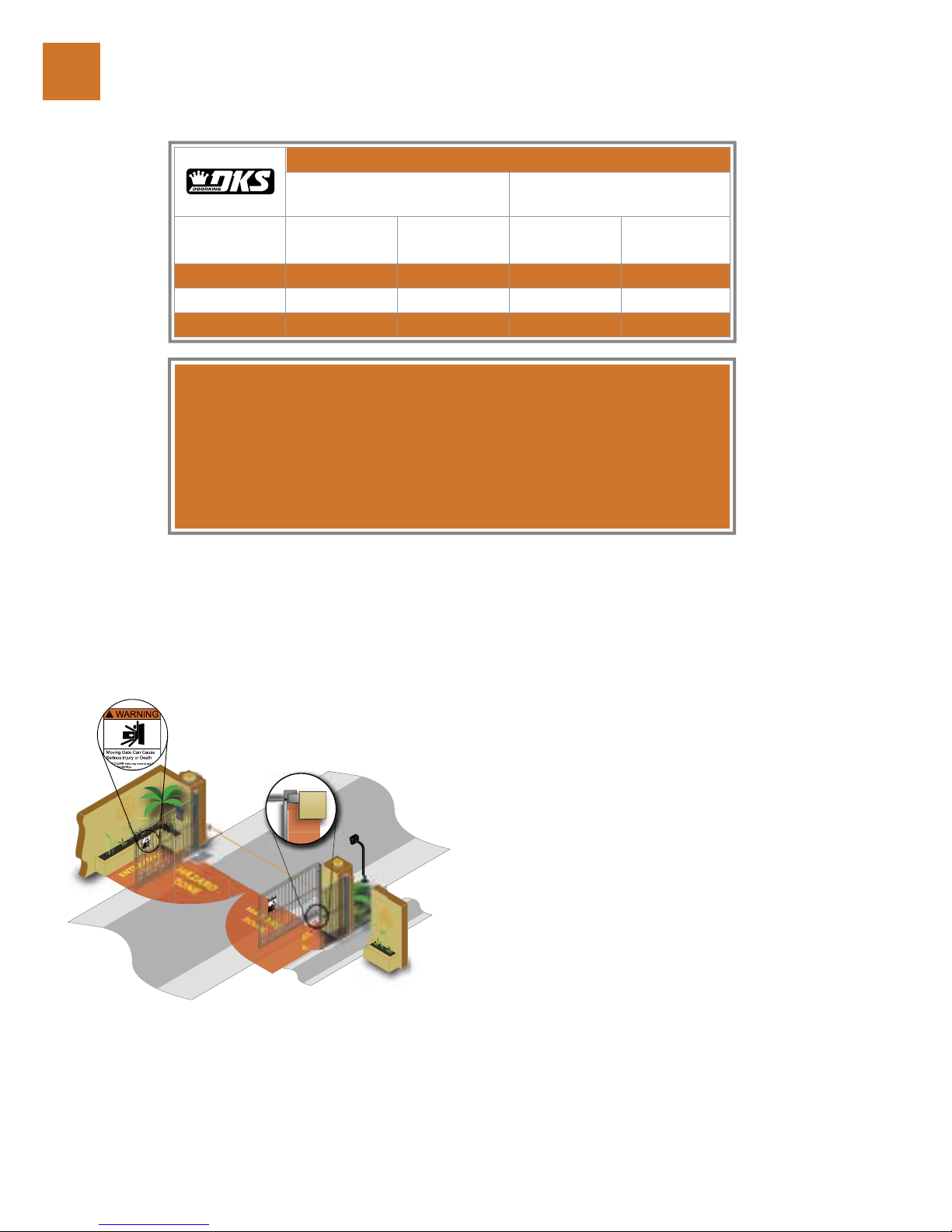
A minimum of two (2)WARNING SIGNS shall be installed,
one on each side of the gate where easily visible.
For gate operators utilizing a non-contact sensor:
1. See the instructions on the placement
of non-contact sensors for each type
of application.
2. Care shall be exercised to reduce the risk of
nuisance tripping, such as when a vehicle
trips the sensor while the gate is still moving
in the opening direction.
3. One or more non-contact sensors shall
be located where the risk of entrapment or
obstruction exist, such as the perimeter
reachable by a moving gate or barrier.
For gate operators utilizing contact sensors:
1. One or more contact sensors shall be
located where the risk of entrapment or
obstruction exist, such as at the leading
edge, trailing edge, and post mounted both
inside and outside of a vehicular horizontal
slide gate.
2. One or more contact sensors shall be
located at the bottom edge of a vehicular
vertical lift gate.
3. One or more contact sensors shall
be located at the pinch point of a
vehicular vertical pivot gate.
4. A hardwired contact sensor shall be
located and its wiring arranged so that the
communication between the sensor and the
gate operator is not subjected to mechanical
damage.
5. A wireless contact sensor such as one that
transmits radio frequency (RF) signals to
the gate operator for entrapment protection
functions shall be located where the
transmission of the signals are not obstructed
or impeded by building structures, natural
landscaping or similar obstructions. A
wireless contact sensor shall function under
the intended end-use conditions.
6. One or more contact sensors shall be located
at the bottom edge of a vertical barrier (arm).
Install the gate operator only if:
1. The operator is appropriate for the construction
of the gate and the usage class of the gate.
2. All openings of a horizontal slide gate are
guarded or screened from the bottom
of the gate to a minimum of 4 feet (1.22 m)
above the ground to prevent a 2 ¼ inch
(57.2 mm) diameter sphere from passing
through the openings anywhere in the gate,
and in that portion of the adjacent fence that
the gate covers in the open position.
3. All exposed pinch points are eliminated or
guarded.
4. Guarding is supplied for exposed rollers.
The operator is intended for installation only on gates
used for vehicles. Pedestrians must be supplied with a
separate access opening. The pedestrian access opening
shall be designed to promote pedestrian usage. Locate
the gate such that persons will not come in contact with
the vehicular gate during the entire path of travel of the
vehicular gate.
The gate must be installed in a location so that enough
clearance is supplied between the gate and adjacent
structures when opening and closing to reduce the risk of
entrapment. Swinging gates should not open into public
access areas.
The gate must be properly installed and work freely in both
directions prior to the installation of the gate operator.
Do not over-tighten the operator clutch, pressure relief
valve or reduce reversing sensitivity to compensate for a
damaged gate.
For gate operators utilizing Type D protection:
1. The gate operator controls must be placed so
that the user has full view of the gate area when
the gate is moving.
2. A warning placard shall be placed adjacent to
the controls.
3. An automatic closing device (such as a timer,
loop sensor, or similar device) shall not be used.
4. No other activation device shall be connected.

6400-065-E-05-07
6 6400 installation guide
general information / entrapment protection
1
This vehicular gate operator is equipped with an inherent adjustable
current sensing system (Type A). This system will sense an obstruction in
both the opening and closing cycles causing the gate to reverse direction
should an obstruction be encountered. If the system detects a second
obstruction before reaching the full open or close limit after the initial
reversal, an alarm will activate and the operator will need to be reset
before resuming normal operation (see pages 21-23).
Test the gate operator monthly, the gate MUST reverse or stop on contact
when an object activates the inherent sensing system. After adjusting the
force or the limit of travel, retest the gate operator. Failure to adjust and
retest the gate operator properly can increase the risk of injury or death.
If any of these functions operate improperly, remove the operator from
service immediately and contact your service dealer.
Loops and loop detectors, photo-cells and other devices must be installed
with this gate operator to prevent the gate from closing on vehicular
traffic.
traffic.
Sufficient clearance should be available between the gate and adjacent
structures when opening and closing to reduce the risk of entrapment.
Gates should not swing into pedestrian access zones.
If entrapment zone is greater than 4” inches, secondary entrapment
protection is required.
If entrapment zone is less than 16” inches, secondary entrapment
protection is required.
If clearance between the gate and adjacent structure is less than 16”
inches, entrapment protection is required, if clearance is more than 16”
inches, entrapment protection is not required.
%.42!0-%.4
COLUMM /
PILASTER
%.42!0-%.4
:/.%
(!:!2$
:/.%
ENTRAPMENT PROTECTION
Horizontal Slide, Vertical
Lift,Vertical Pivot
Swing and Vertical Barrier
(arm)
USAGE
CLASS Primary Secondary Primary Secondary
Vehicular I & II A B1, B2 or D A or C A, B1,B2, C or D
Vehicular III A, B1 or B2 A, B1, B2, D or E A, B1, B2 or C A,B1,B2,C,D or E
Vehicular IV A, B1, B2 or D A, B1, B2, D or E A, B1, B2, C or D A,B1,B2,C,D orE
TYPE A: Inherent entrapment protection system.
TYPE B1: Provision for connection of, or supplied with, a non-contact sensor (photoelectric sensor or
the equivalent). When used as the PRIMARY device, must be monitored.
TYPE B2: Provision for connection of, or supplied with, a contact sensor (edge device or the
equivalent). When used as the PRIMARY device, must be monitored.
TYPE C: Inherent adjustable clutch or pressure relief device.
TYPE D: Provision for connection of, or supplied with, an actuating device requiring continuous
pressure to maintain opening or closing motion of the gate.
TYPE E: An inherent audio alarm.

6400-065-E-05-07 6400 installation guide 7
1
general information / glossary
GATE – A moving barrier such as a swinging, sliding, raising, lowering, or the like, barrier, that is a
stand-alone passage barrier or is that portion of a wall or fence system that controls entrance and/or
egress by persons or vehicles and completes the perimeter of a defined area.
RESIDENTIAL VEHICULAR OPERATOR-CLASS – A vehicular gate operator (or system)
intended for use in a home of one-to four single family dwelling, or garage or parking area associated
therewith.
COMMERCIAL / GENERAL ACCESS VEHICULAR OPERATOR-CLASS II – A vehicular
gate operator (or system) intended for use in a commercial location or building such as a multi-family
housing unit (five or more single family units), hotels, garages, retail store, or other building servicing
the general public.
INDUSTRIAL / LIMITED ACCESS VEHICULAR OPERATOR-CLASS III – A vehicular
gate operator (or system) intended for use in an industrial location or building such as a factory or
loading dock area or other locations not intended to service the general public.
RESTRICTED ACCESS VEHICULAR OPERATOR-CLASS IV – A vehicular gate operator
(or system) intended for use in a guarded industrial location or building such as an airport security area
or other restricted access locations not servicing the general public, in which unauthorized access is
prevented via supervision by security personnel.
VEHICULAR BARRIER (ARM) OPERATOR (OR SYSTEM) – An operator (or system) that
controls a cantilever type device (or system), consisting of a mechanical arm or barrier that moves in a
vertical arc, intended for vehicular traffic flow at entrances or exits to areas such as parking garages, lots
or toll areas.
VEHICULAR HORIZONTAL SLIDE-GATE OPERATOR (OR SYSTEM) – A vehicular gate
operator (or system) that controls a gate which slides in a horizontal direction that is intended for use for
vehicular entrance and exit to a drive, parking lot, or the like.
VEHICULAR SWING-GATE OPERATOR (OR SYSTEM) – A vehicular gate operator (or
system) that controls a gate which moves in an arc in a horizontal plane that is intended for use for
vehicular entrance and exit to a drive, parking lot, or the like.
SYSTEM – In the context of these requirements, a system refers to a group of interacting devices
intended to perform a common function.
WIRED CONTROL – A control implemented in a form of fixed physical interconnections between
the control, the associated devices, and an operator to perform predetermined functions in response to
input signals.
WIRELESS CONTROL – A control implemented in means other than fixed physical interconnections
(such as radio waves or infrared beams) between the control, the associated devices, and an operator to
perform predetermined functions in response to input signals.
INHERENT ENTRAPMENT SENSOR SYSTEM – An automatic sensor system that senses
entrapment of a solid object and is incorporated as a permanent and integral part of the operator.
EXTERNAL ENTRAPMENT PROTECTION DEVICE – A device, examples being an edge
sensor, a photoelectric sensor, or similar entrapment protection device, which provides protection
against entrapment when activated and is not incorporated as a permanent part of an operator.
ENTRAPMENT – The condition when an object is caught or held in a position that increases the risk
of injury.

6400-065-E-05-07
8 6400 installation guide
Class of Operation:
Class I, Underground Residential Swing Gate
Actuator
Type of Gate:
Residential Swing Gates Only
Max Torque:
300Nm
Input Voltage / Operator Voltage:
24 VAC Single Phase Power Input
(transformer provided)
24 VDC
Current:
3 amps
Max Gate Length:
10 Ft.
Max Gate Weight:
300 lb.
Cycles / Hr:
20/Hr with AC Power Transformer Connected
Speed:
90° in approximately 20 seconds
Entrapment Protection:
Primary - Inherent adjustable current sensor
(Type A)
Secondary - Provision for connection of non-
contact (Type B1) sensors.
Operator
Cover Plate
Gate Support Bracket
Cover Plate Hinges
general information / specifications
1
Foundation Box
Pinion
Release Arm
Limit Switch Plate
Crank Connecting Assembly
Locking Bracket
Conduit Hole
Drain Pipe Hole
Lubrication Slot

6400-065-E-05-07 6400 installation guide 9
2
underground operator installation / enclosure
BEFORE INSTALLING THE GATE OPERATOR
Review the operator specifications on page 7.
Review the operator installation dimensions.
Operator and gate should be installed in conjunction to ensure proper alignment
when opening.
Gate should be mounted on heavy-duty ball bearing hinges.
Gate MUST swing freely without binding.
Never attempt to manually operate any gate until the power has been shut-off
unless otherwise specified.
17.6
6.25
12.6
1
2
Dig a hole for the enclosure box
using the gate hinge as a center line,
see illustration for dimensions.
Remove components from
the foundation box before
setting in to place.
NOTE: Dimensions
may differ slightly
when fitting in the
enclosure.
Gate Hinge
NOTE: Depending on soil
conditions a concrete base
may need to be applied to
avoid run-off.

6400-065-E-05-07
10 6400 installation guide
2
3
Install electrical and drainage PVC conduits:
Run ectrical conduit from the foundation box to the
control/junction box.
Run drainage conduit from the foundation box to the
nearest drain.
underground operator installation / enclosure
Place the enclosure box inside the
hole ensuring it is leveled and the gate
hinge is centered with the operator
pivot.
4
Pour concrete around the
enclosure box to set in place:
Cover exposed holes
avoiding any concrete to
seep inside the enclosure
box.
Confirm the operator pivot
and door hinge are centered
and conduits are in position.
5
Gate Hinge
Centered With
Operator Pivot.
Operator Pivot
Drainage Conduit
Electrical Conduit
Pour Concrete
Around the
Edge of the
Foundation
Box.
NOTE: Concrete base
should be fully cured
before setting the
foundation box.
NOTE: Improper drainage will
result in stagnant water leading to
component failure.
NOTE: Concrete should
be fully cured before
installing motor.

6400-065-E-05-07 6400 installation guide 11
2
underground operator installation / gate mount
Reinstall the motor assembly.
1
Pivot and
Bearing
Weld the gate U-Channel
onto the gate support
bracket.
Weld on both sides.
Cover the components
avoiding weld scale
damage.
2
Install the crank
connecting assembly.
Gate MUST be
closed or at the
90 degree position
when installing the
crank connecting
assembly.
3
Install the gate on to the hinge and the
U-Channel, gate should swing freely
90 degrees.
4
Crank Connecting
Assembly
Grease the pivot,
and bearing and set
components in place
(see illustration for
assembly installation).
5
Operator configuration
for biparting double door
installation.
The output shaft of the operator MUST be oriented on the outside of the gate, the motor/
gearbox and limit assembly may have to change.
Remove the four nuts holding the limit bracket, loosen the magnetic limit switches
and slide them 90°
Remove the four nuts holding the motor/gearbox, rotate the unit 180° and reinstall in the
mounting box with the limit assembly.
The LEFT HAND motor wires connect to the PRIMARY terminals. The RIGHT HAND
motor wires connect to the SECONDARY terminals. IMPORTANT: The left motor wires
BROWN and BLUE are interchanged on the right side motor to BLUE and BROWN.
1
3
4
1
2
3
2
NOTE: Locking bracket
and gate support should
be in place at 90 degrees.
DoorKing does
not provide the
U-CHANNEL, it
must be fabricated
according to existing
gate dimensions.

6400-065-E-05-07
12 6400 installation guide
X0REDRILLED
-OUNTING(OLES
CONTROLBOX
WHEN INSTALLING THE CONTROL BOX
Be sure the circuit breaker in the electrical panel is in the OFF
position.
Permanent wiring must be installed to the operator as required by local
electrical codes. It is recommended that a licensed electrical contractor
perform this work. Check local building codes prior to installing any
permanent wiring to ensure all wiring and connections comply with local
electrical code requirements.
Control Panel must be properly grounded.
Be sure the control box is properly supported to avoid injury and damage
to the control box.
It may be necessary to temporarily remove the control box components to
avoid any damage when installing.
Depending on installation it may be necessary to drill additional mounting
holes in the control box.
Temporarily cover the terminal strip with tape to avoid damage.
1Place the control box in the desired
mounting position, mark and create
the mounting holes.
electrical installation / control box mounting
3
2Mount and secure the control box
using appropriate hardware. Install
the control box so that the primary
actuator cable can be easily routed
into the control box.
1
1

6400-065-E-05-07 6400 installation guide 13
3,/$7.
,)-)4
-/4/2
-/4/2
#/--/.
#/--/.
,)-)4
3,/$7.
#OMMON
#LOSE%DGE
#OMMON
3%#/.$!29
BROWN (2)
RED (4)
YELLOW (5)
GREEN (6)
GRN/WHT (YEL)
BLUE (1)
ORANGE (3)
3,/$7.
,)-)4
-/4/2
-/4/2
#/--/.
#/--/.
,)-)4
3,/$7.
02)-!29
+%9
37)4#(
BLUE (2)
RED (4)
YELLOW (5)
GREEN (6)
GRN/WHT (YEL)
BROWN (1)
ORANGE (3)
3,/$7.
,)-)4
-/4/2
-/4/2
#/--/.
#/--/.
,)-)4
3,/$7.
#OMMON
#OMMON
3,/$7.
,)-)4
-/4/2
-/4/2
#/--/.
,)-)4
3,/$7.
3%#/.$!29
+%9
Primary Motor
Interface Cable.
1Connect the PRIMARY
actuator cable to the control
panel as shown.
2Connect the SECONDARY
actuator cable to the control
panel as shown.
electrical installation / actuator wiring 3
Secondary Motor Interface Cable.
Secondary Junction Box.
Previous actuators came with numbered wires. The number
on the right of the wire color indicates this wiring scheme. If the
cable includes a white wire, do not use or connect it.
When installing electrical equipment make certain all wiring
complies with local code requirements.
Proceed to step 2 if installing a secondary actuator .
Components not included, each must be purchased separately.
1
1
2
2
2
1

6400-065-E-05-07
14 6400 installation guide
24V COMMON
RADIO RELAY / OPEN INPUT
24V DC RADIO PWR
OPEN INPUT / EXIT LOOP LOGIC OUTPUT
24V COMMON
OPEN INPUT
24V COMMON
REVERSE / SHADOW INPUT
24V COMMON
RELAY
RELAY
24 VDC LOCK OUTPUT
24 VDC LOCK OUTPUT
NOT USED
12V BATT +
NOT USED
ALARM RESET
24V COMMON
24 VAC INPUT
24 VAC INPUT
RED 12 AWG
BLACK
WHITE
GREEN
1
2
3
4
5
6
7
8
9
10
11
12
13
14
15
16
17
18
19
20
Tele
p
hone 115 VAC
PushButton
ToCall
3-Wire
WHITE
BLACK
Function dependant on SW1, switch 3
Transformer enclosure
located in control box.
Wire nut 115 VAC input
power to Black and White
transformer wires.
Function dependant on SW1, switch 5
Function dependant on SW2, switch 1, 2
Controls must be far enough from the
gate so that the user is prevented from
coming in contact with the gate while
operating the controls. Outdoor or
easily accessible controls should have a
security feature to prevent unauthorized use.
When installing electrical equipment make
certain all wiring complies with local code
requirements.
Do not power any devices from the circuit
board other than a low voltage radio
receiver.
Reversing input (Terminal 8) only
functions while the gate is at the
full open position or during the closing
cycle should not be used as an input for a
secondary entrapment protection device
during the opening gate cycle. Refer to the
Secondary Entrapment Protection Device
Wiring section.
Connect optional control devices to
the main terminal strip. Use 18 AWG
wire for all low voltage wiring, maximum
distance 3000 feet. Use a low voltage surge
suppressor, (DoorKing P/N 1878-010) if low
voltage wire runs exceed 1000 feet. All inputs
to the terminal strip must be NORMALLY
OPEN.
electrical installation / main terminal wiring
3
1
2
1
2

6400-065-E-05-07 6400 installation guide 15
electrical installation / main terminal wiring 3
TERMINAL DESCRIPTION
1. 24V COMMON
2. RADIO RELAY - SINGLE BUTTON ACTIVATION INPUT
• When gate is closed, input will open gate.
• When gate is open and auto close timer is turned on, input will re-set the hold timer.
• When gate is open and auto close timer is turned off, input will close gate.
• When gate is closing, input will reverse gate.
3. 24V DC RADIO POWER
4. SINGLE BUTTON ACTIVATION INPUT / EXIT LOOP LOGIC OUTPUT
• If SW 1, switch 3 is ON, this input is identical to Single Button Activation Input (Terminal 2).
• If SW 1, switch 3 is OFF, this terminal becomes the logic output of the EXIT loop detector.
5. 24V COMMON
6. OPEN INPUT
7. 24V COMMON
8. REVERSE INPUT / SHADOW INPUT
• When gate is closed, this input has no affect on the gate operator.
• When gate is open and auto close timer is turned ON, input will re-set and hold timer.
• When gate is open and auto close timer is turned OFF, input will prevent gate from closing.
• During CLOSING cycle of gate:
SW 1, Switch 5 OFF = Term 8 is Reversing Input.
SW 1, Switch 5 On = Term 8 is Shadow Input. Disabled During CLOSING CYCLE.
9. 24V COMMON
10. DRY RELAY CONTACT
• Operation of relay is dependent on setting of SW 2, switches 1 and 2. Relay contacts
can be set for Normally Open (NO) or Normally Closed (NC) operation. Contact
rating is 1 amp maximum at 24 Volts.
• Switch 1 OFF, Switch 2 OFF: Relay activates when gate is OPEN.
• Switch 1 OFF, Switch 2 ON: Relay activates when gate is OPEN, OPENING or CLOSING.
• Switch 1 ON, Switch 2 OFF: Relay activates when gate is OPEN or OPENING.
• Switch 1 ON, Switch 2 ON: Relay activates when gate is OPENING or CLOSING.
11. DRY RELAY CONTACT
12. SW2 - 3 ON MAG LOCK 1 SECOND DELAY AT START
13. SW2 - 3 OFF SOLENOID LOCK 4-5 SECOND DELAY AT START
14. Not Used
15. 12 VOLT BATTERY +
16. Not Used
17. ALARM RESET
18. 24V COMMON
19. 24 VAC INPUT
20. 24 VAC INPUT
*NOTE: DC power is not present on the board until the first initial cycle.

6400-065-E-05-07
16 6400 installation guide
8 9
0HOTO#LOSE
0HOTO/PEN
/PEN%DGE
#OMMON
#LOSE%DGE
#OMMON
3electrical installation / entrapment protection wiring
The swing gate operator uses
an inherent entrapment sensing
system (Type A) and comes
equipped ready to connect a secondary
entrapment protection device. Entrapment
protection devices are required to reduce
the risk of injury. Install sensors where the
risk of entrapment or obstruction exists
while gate/barrier is moving.
UL INPUTS
1 PHOTO OPEN
If the open photo-beam is activated during the opening cycle, the
gate will stop. The gate will remain stopped until the photo-beam
input is cleared, at which time the gate will resume the open cycle.
2 PHOTO CLOSE
If the close photo-beam input is activated during the closing cycle,
the gate will stop. The gate will remain stopped until the photo-
beam input is cleared, at which time the gate will resume the close
cycle.
3 OPEN EDGE
4 CLOSE EDGE
5 COMMON: terminal for the secondary entrapment protection
device inputs.
6 COMMON
3Route and connect the PHOTO
OPEN cable to the UL INPUTS
as shown.
2Route and connect the STAN-
DARD REVERSE cable to the
main terminal strip as shown.
1Disconnect power to the gate
operator before installing the
sensors.
3
2
2
3

6400-065-E-05-07 6400 installation guide 17
REVERSE
LOOP
EXIT LOOP
CTOR
-010
PREVERSE
LOOP
LOOP DETECTOR
P/N 9406-010
TB 1
LOOP DETECTOR
P/N 9406-010
EXIT
LOOP
LOOP
P/N
TB 1
TB 1
electrical installation / exit/reverse loop detector wiring 3
3Route and connect the
REVERSE LOOP DETECTOR
cable as shown.
2Route and connect the EXIT
LOOP DETECTOR cable as
shown.
1Disconnect power to the gate
operator before installing the
loop detector wiring.
To protect the gated area from accidentally closing on vehicles a
series of Loop Detectors must be installed. Loops are laid underneath,
cut into asphalt or concrete driveways or buried beneath gravel and
earth driveways. A Loop Detection system will sense a vehicle like a
metal detector and send a signal to the gate operator preventing the gate from
automatically closing on a vehicle when exiting.
EXIT LOOP
An exiting vehicle will activate the Exit Loop and automatically open the gate
when exiting the property without having to use a transmitter or keypad.
The Exit Loop can be placed 20-100 feet before the gate so that the gate is
open or partially open as you drive up to it.
REVERSE LOOP
Will stop or reverse the close cycle of an automatic gate preventing the gate
from closing while a vehicle is exiting or stopped in the gate area.
Refer to the separate Loop and Loop Detectors Information Manual (Loop
Info G-3-02) when installing loops.
3
2

6400-065-E-05-07
18 6400 installation guide
SHADOW
LOOP
3,/$7.
,)-)4
-/4/2
-/4/2
#/--/.
#/--/.
,)-)4
3,/$7.
02)-!29
+%9
37)4#(
1 2 3 4 5 6 7 8 9 1011121314151617181920
3,/$7.
,)-)4
-/4/2
-/4/2
#/--/.
#/--/.
,)-)4
3,/$7.
0HOTO#LOSE
0HOTO/PEN
/PEN%DGE
#OMMON
#LOSE%DGE
#OMMON
37
2%$
#(!2'%$
#(!2').'
4)-%
'2%%.
2%3%4 #/092)'(4
$//2+).'
2%6%23%,//0%8)4,//0
3%#/.$!29
8 9 10 11
SHADOW
LOOP
LOOP DETECTOR
P/N 9405-010
TB 1
TB 2
C
NC
NO
SHADOW LOOP
electrical installation / shadow loop detector wiring
3
2Route and connect the
SHADOW LOOP DETECTOR
cable as shown.
1Disconnect power to the gate
operator before installing the
loop detector wiring.
A Shadow Loop is placed inside the swing gate area to prevent the gate from
closing on a vehicle that is in the path of the gate after the open time has
expired or the Exit Loop is too far back from the Reverse Loop. The Shadow
Loop is only active when the gate is in the full open position and will not allow the swing
gate to close. Once the close cycle begins the Shadow loop will not reverse the gate.
For correct SHADOW LOOP operation, jumper wire must be placed from terminal
9 to terminal 10. SW1 switch 5 must be OFF, SW2 switch 1 must be ON and SW2
switch 2 must be OFF.
Output of Shadow Loop Detector may be connected directly to terminals 8 and 9
(dotted line - no jumper required between 9 and 10) if SW 1, switch 5 is ON. However,
with this switch ON, terminal 8 becomes a shadow input (active only when the gate is
FULL OPEN) and all reversing devices connected to terminal 8 will operate as shadow
devices. If this is not desirable, wire the shadow loop detector as instructed above.
Refer to the separate Loop and Loop Detectors Information Manual (Loop Info G-3-02)
when installing loops.
1
1

6400-065-E-05-07 6400 installation guide 19
PRIMARY
MIN MAX
SECONDARY
REVERSE SENSOR
MIN MAX
0 - 23 Seconds
SW1, Switch 4 ON
SW1 SW2
1
2
3
4
5
6
7
8
1
2
3
4
ON
3,/$7.
,)-)4
-/4/2
-/4/2
#/--/.
#/--/.
,)-)4
3,/$7.
0HOTO#LOSE
0HOTO/PEN
/PEN%DGE
#OMMON
#LOSE%DGE
#OMMON
37
3,/$7.
,)-)4
-/4/2
-/4/2
#/--/.
#/--/.
,)-)4
3,/$7.
2%$
#(!2'%$
#(!2').'
2%3%4 #/092)'(4
$//2+).'
2%6%23%,//0%8)4,//0
3%#/.$!29
02)-!29
+%9
37)4#(
1234567891011121314151617181920
3
7
%
%3
3,
-34
#
4)-%
$%,!9
NC
NO
Relay Contact Setting
NO - Relay Normally Open (factory)
NC - Relay Normally Closed
settings / control board adjustment 4
Function Switches
The switch settings and adjustments in this section should be made after the
installation and wiring to the operator(s) is complete (see illustration).
The two DIP-switches on the circuit board are used to program the actuators to
operate in various modes and to turn on or off various operating features. Check
ALL switch settings before applying power to the control panel (refer to switch
settings).
Whenever any programming or switch setting on the circuit board is changed, batteries
must be disconnected and main power must be shut-off. Once completed turn main
power on and re-connect the batteries. The new programming and settings will not take
effect unless this procedure is followed.
Close Timer
Reverse Sensors
Relay Jumper
1
1
3
4
2
1
2
3
4

6400-065-E-05-07
20 6400 installation guide
SW1 Switch 1: Sets direction of the Primary actuator so that it cycles open upon initial power up and open command. If the actuator begins
to cycle close upon initial power up and open command, turn power off and change the setting on this switch.
SW1 Switch 2: Sets direction of the Secondary actuator so that it cycles open upon initial power up and open command. If the actuator begins
to cycle close upon initial power up and open command, turn power off and change the setting on this switch.
SW1 Switch 3: Determines if the output of the loop detector (DoorKing loop detectors only) plugged into the EXIT port will be sent directly to
the microprocessor to open the gate, or if the output is directed to terminal 4 where it can then be connected to other input
terminals.
SW1 Switch 4: Turns the auto close timer on or off. Maximum time that the close timer can be set for is 23 seconds.
SW1 Switch 5: Sets the input to terminal 8 to act as a standard reverse input (OFF) or to act as a shadow input (ON). If shadow setting is
used, input to terminal 8 will only hold the gate in the full open position. Once the gate begins to close, the input will not reverse
the gate.
SW1 Switch 6: Turns the overlap feature on or off. When turned ON, the Secondary actuator begins its cycle 1-2 seconds prior to the Primary
actuator, allowing the Primary gate to reach its full closed position 1-2 seconds before the Secondary gate. This feature is
useful when a magnetic lock is used to secure the gates.
SW1 Switch 7: Sets up the circuit board for single or dual (Primary / Secondary) gate operation.
SW1 Switch 8: Spare switch. Leave in the OFF position.
SW2 Switches 1-2: Work in conjunction with each other and determine when the relay on the board will be activated. This relay can be used as a
switch for various functions such as illuminating a warning light when the gate is moving, or turning on a green light when the
gate is full open. This relay is not available for these uses if it is being used for the shadow loop function.
Switches 3-4: Spare switches. Leave these in the OFF position.
settings / switch descriptions & functions
4
Switch Function Setting Description
1Direction
Primary
Set this switch so that the Primary actuator runs OPEN after
initial power up and activation.
2Direction
Secondary
Set this switch so that the Secondary actuator runs OPEN
after initial power up and activation.
3Exit Loop
Logic Output
OFF
ON (normal)
Output of loop detector in EXIT port is switched to terminal 4.
Output of loop detector in EXIT port feeds directly to processor.
4Auto Close
Timer
OFF
ON
Auto-close timer is OFF. Manual input required to close gate.
Auto-close timer is ON. Adjustable from 1-23 seconds.
5Reverse
Shadow
OFF (normal)
ON
Terminal 8 is STANDARD reverse input.
Terminal 8 is SHADOW reverse input.
6Overlap OFF
ON
Both actuators start at same time.
Secondary actuator starts 1-2 seconds prior to the Primary actuator.
7Single
Dual
OFF
ON
Switch is OFF for a single actuator.
Switch is ON for two actuators (Primary / Secondary).
8 Not Used OFF Leave in OFF position.
Switch Function Setting Description
1 and 2 Relay
Operation
1-OFF 2-OFF
1-OFF 2-ON
1-ON 2-OFF
1-ON 2-ON
Relay activated only when gate is FULLY OPEN
Relay activated whenever gate is NOT CLOSED
Relay activated when gate is OPENING or OPEN
Relay activated when gate is OPENING or CLOSING
3Mag-Lock
Solenoid
ON
OFF
1 Second Delay
4-5 Second Delay
4 Not Used OFF LEAVE in OFF position
SW2 (bottom switch) SW1 (top switch)
Table of contents
Other DKS Gate Opener manuals

DKS
DKS 9100 Operating instructions

DKS
DKS 6002 User manual

DKS
DKS 6003 User manual

DKS
DKS Series 6050 User manual

DKS
DKS 9200 "Full Open" User manual

DKS
DKS 9100 User manual

DKS
DKS 9310 User manual

DKS
DKS Series 6550 Operating instructions

DKS
DKS 9000-080 Operating instructions

DKS
DKS Series 6050 Operating instructions