FIG. 4B TOP
SLAT
(9000
Awnings)
INSTALLATION
COVEREDBYPATENT4,524,791;5,351,736;5,566,918;
5,383,346; D353,473, others pending
Application
TheA&Eawningwith"UniversalHardware"isdesignedand
intended for use on motorhomes, mini-motorhomes, 5th
wheels and travel trailers with straight or curved sides. For
curved sides, please see the separate Hardware List in the
DealerServiceManualfortheappropriatemodel.
IMPORTANT: Read and understand ALL of the follow-
ing steps before beginning installation.
TheDometicCorporationreservestherighttomodifyappear-
ances and specifications without notice.
InstallationofA&EAwningswillbrieflyrequirethreepeople.
Use the following procedure to assure a properly installed,
andproperlyfunctioningawning.
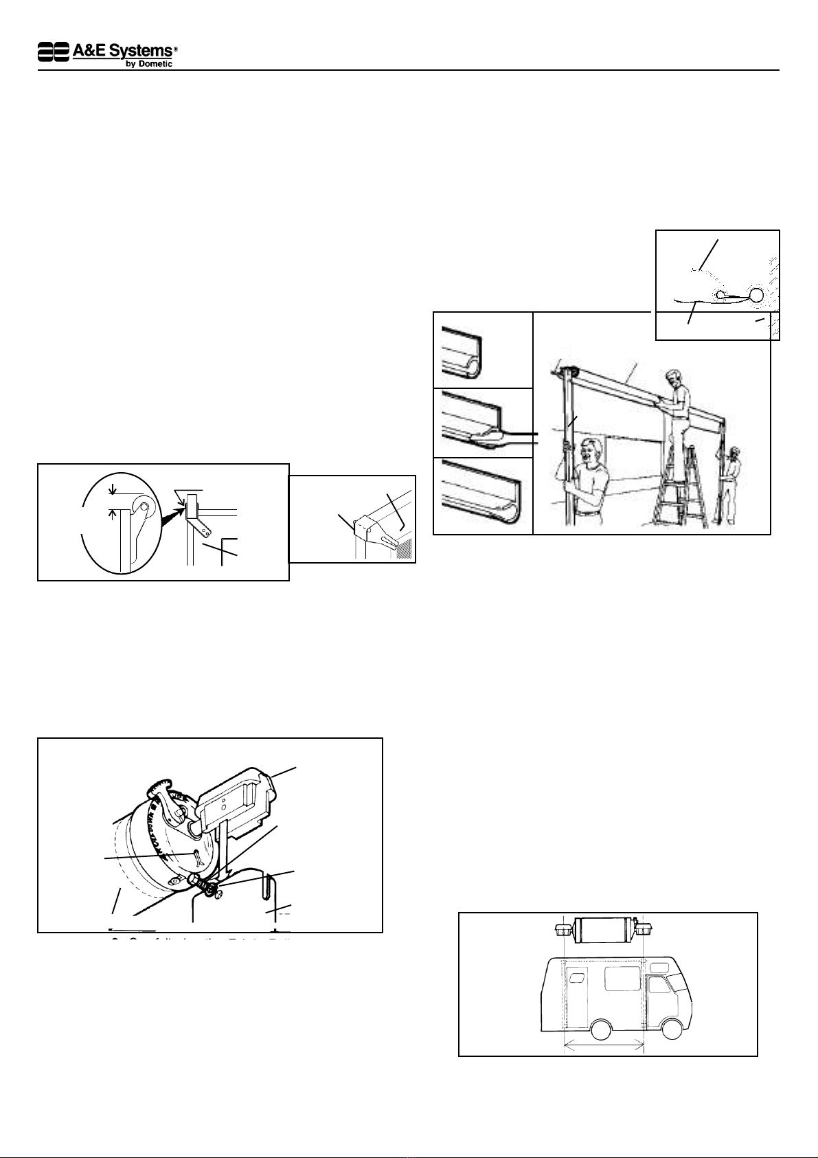
1. Wherethe awning is mounted above the entry door, the
door roller must be installed on the outside of the door
intheextremeupper cornerabove thedoor handle.
(FIG.1A)
A door screen edge guard must be installed on the
outside of the screen door in the extreme upper corner
oppositethedoor hinges.(FIG. 1B)
When the entry or screen door is opened while the
awning fabric is extended low, the door roller or edge-
guard (instead of the sharp door corner) contacts the
undersideofthefabric.
2. Carefully lay the fabric roller tube assembly on "V"
troughsorotherwellprotectedsurfacetopreventfabric
damage. Secure arm assemblies totherespective top
castings using 1/4–20 x 1/2" hex. hd. machine screws
and 1/4" lock washers. (FIG. 2)
CAUTION: DO NOT REMOVE the cotter pins at this
time and DO NOT attempt to rotate the Safe-T-LockTM
Lever until installation is complete. (Lever is pre-set
in the roll-up position.) (FIG. 2)
FIG. 4A
AWNING
RAIL FABRIC ROLLER
TUBEASSEMBLY
ARM
ASSEMBLY
3. Prepare the awning rail to accept the awning roller
cover. Select the end from which the awning shall be
fed,thenwidenthatendoftherailwithaflatscrewdriver
andfileoff anysharpedges. (FIG.3)
4. Withonepersongraspingeachsupportarm,carefully
lift the entire assembly upright. Keep the two arm
assemblies Parallel to each other to avoid damage
due to twisting Carry the awning to the prepared
awning rail end. (FIG. 4A & B)
Feedtherollercoverintotheawningrailwhilestanding
onastepladder,(thirdperson)whiletwocarrytheawning
assembly to the desiredposition.
5. Install TopBrackets
Afterthecompleteawningassemblyhasbeenthreaded
into the awning rail, check to be sure that its position
allows for solid mounting of the top and bottom
brackets and thatsupport arms are indesired location
(not restricting use of doors, access doors, egress
windows, etc.). (FIG.5A)
Dometic
1/4–20 X 1/2"
HEX HD.
MACH. SCREW
LOCK
WASHER
ARM
DONOT
REMOVE
C O T T E R
PIN AT
THISTIME
FIG. 2
DONOTROTATE
SAFE-T-LOCK TM
LEVER
FIG. 1B SCREEN
DOOR
DOOREDGE
Wheel Above
Door 1/4" –3/8"
Position Wheel
Directly over edge
of Door