Dorma ED 200 User guide

ED 200
194 605-01-6-50
DORMA
ED 200
Montageanleitung
Mounting instruction

DORMA
Drucktechnisch bedingte leere Seite Blank page on account of printing technology

ED 200
194 605-01-6-50
DORMA
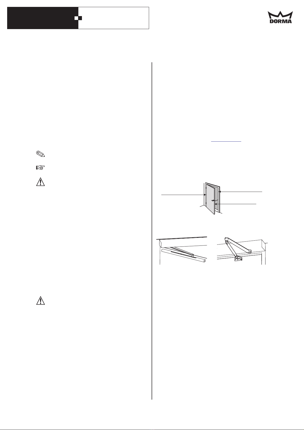
Nebenschließkante Gegenschließkante
Hauptschließkante
Diese Dokumentation enthält wichtige Anweisungen für die
Montage und den sicheren Betrieb. Lesen Sie diese
Anweisungen, bevor Sie den verwenden.
Eine falsche Montage kann zu schwerwiegenden
Verletzungen führen.
Die Verwendung von Steuerelementen, Einstellungen oder
Verfahren, die in dieser Dokumentation nicht beschrieben
sind, können elektrische Schläge, Gefahren durch
elektrische Spannungen/Ströme und/oder Gefahren durch
mechanische Vorgänge verursachen.
Die Unterlagen sind aufzubewahren und bei einer
eventuellen Weitergabe der Anlage mit zu übergeben.
Eine Anmerkung macht auf wichtige
Informationen aufmerksam, die Ihnen
die Arbeit erleichtern.
Ein Hinweis warnt vor möglichen
Beschädigungen des Gerätes und
erläutert, wie diese verhindert werden
können.
Weist auf Gefahren hin, die zu
Sachschäden, Personenschäden oder
zum Tod führen können.
Der ist ein elektromechanischer/
elektrohydraulischer Antrieb und dient ausschließlich zum
Öffnen und Schließen von Drehtüren im Innenbereich mit
einem zulässigen Türflügelgewicht bis 250 kg. In
Verbindung mit Fluchtwegsicherungssysteme ist der
zur Verwendung an gesicherte Flucht und Rettungswegtüren
einsetzbar. D uch an Brandschutztüren
(Feuer-/Rauchschutztüren) Verwendung.
Die maximale Kabellänge externer Komponenten darf 30 m
nicht übersteigen.
Die Anbindung an den Türflügel erfolgt über: Gleitschiene
und Hebel oder Standardgestänge.
Der darf nur gemäß seiner bestimmungsgemäßen
Verwendung eingesetzt werden. Eigenmächtige Änderungen
am schließen jede Haftung durch die
für daraus resultierende Schäden
aus. Für die Verwendung von Zubehör, das von
nicht freigegeben ist wird keine Haftung übernommen.
Kinder nicht mit dem der seine Regel- und
Steuereinrichtungen spielen lassen.
Führen Sie niemals Metallgegenstände in die
Öffnungen des ein. Andernfalls besteht die
Gefahr eines elektrischen Schlages
Wird der auf ein metallisches Türblatt
montiert, muss das Türblatt ordnungsgemäß geerdet
werden.
Für Glastürflügel muss Sicherheitsglas verwendet
werden.
Gewicht des 18 kg
Spannungsversorgung 230V DC +-10%
Leistungsaufnahme 150W
Betriebsgeräusch < 70 dB(A)
ED 200
Für Ihre Sicherheit ist es wichtig, allen beiliegenden
Anweisungen Folge zu leisten.
In dieser Anleitung benutzte Symbole
ANMERKUNG
HINWEIS
ACHTUNG
Bestimmungsgemäßer Gebrauch
ED 200
Haftungsbeschränkung
ED 200
ED 200
DORMA GmbH + Co. KG
DORMA
Sicherheitshinweise
Arbeiten an Elektroanlagen dürfen nur von geschulten
Fachkräften (Elektriker) ausgeführt werden.
ED 200
ED 200
ED 200
Wichtige technische Daten
ED 200
•
•
•
•
•
•
•
•
ED 200
ED 200er findet a
Normen, Gesetze, Richtlinien und Vorschriften
Hinweise/Vorschriften bei der Verwendung des ED 200 an
Feuer- und Rauchschutztüren:
DIN 18650
PRODUKTE www.dorma.de
Gefahren an Schließkanten
An automatischen Türen können an den verschiedenen
Schließkanten Quetsch-, Scher-, Stoß- und
Einzugsgefahren bestehen.
Gefahren durch Gleitschienenhebel und Gestänge
An Gleitschienenhebel und Gestänge bestehen
Quetsch- und Schergefahren.
Restrisiko
•
•
•
Der neueste Stand der allgemein gültigen und länder-
spezifischen Normen, Gesetze, Richtlinien und
Vorschriften ist einzuhalten.
Merkblatt über die Verwendung von Feststellanlagen
benutzen.
Richtlinien für Feststellanlagen des Instituts für
Bautechnik, Berlin benutzen.
Der Hersteller (die Person, die den Einbau vornimmt) und
der Auftraggeber/Betreiber müssen bei der Planung der
Anlage gemeinsam eine individuelle Risikobeurteilung
durchführen.
Wir verweisen hierzu auf das zur Unterstützung der
Durchführung zur Verfügung stehende Formular
"Risikobewertung", Sie erhalten es unter dem Register
auf unserer Internetseite .
Je nach baulicher Gegebenheit, Türvariante und
Absicherungsmöglichkeit können Restgefahren (z. B.
Quetschen, kraftbegrenztes Anstossen) nicht
ausgeschlossen werden.
Die an jeder (auch manuell betriebenen) Drehflügeltür
bestehende Gefahrenstelle an der Nebenschließkante ist
allen Nutzern einer Tür allgemein bekannt. Sie ist durch
den Antriebshersteller nicht beeinflussbar, und ihre
Absicherung ist konstruktiv und funktionell technisch oft
nicht möglich.
Ein hierzu etwaiger geeigneter Klemmschutz (z.B. Gummi-
oder Textilabdeckung) ist im Fachhandel erhältlich und
nicht Gegenstand des Lieferumfanges.
1. Zu Ihrer Sicherheit
3

DORMA ED 200
194 605-01-6-50
Wartung
ED 200
DORMA
Pflege
ED 200
ED 200
ED 200
Wartungsarbeiten dürfen nur im spannungsfreien Zustand
durchgeführt werden. Netzstecker ziehen oder bei
Festanschluss Sicherung ausschalten.
Weitere Hinweise und Vorschriften zur Verwendung des
an Feuer- und Rauchschutztüren finden Sie im
Merkblatt über die Verwendung von Feststellanlagen.
Es empfiehlt sich mit einen Wartungsvertrag
abzuschließen.
Reinigungsarbeiten dürfen nur im spannungsfreien Zustand
durchgeführt werden. Netzstecker ziehen oder bei
Festanschluss Sicherung ausschalten.
Der kann mit einem feuchten Tuch und
handelsüblichen Reinigern gereinigt werden.
Scheuermittel sollten nicht verwendet werden, da sie die
Oberfläche beschädigen könnten.
Lassen Sie kein Wasser oder andere Flüssigkeiten auf oder
in den gelangen.
Führen Sie niemals Metallgegenstände in die Öffnungen am
ein. Andernfalls besteht die Gefahr eines
elektrischen Schlages.
Das Gleitstück
Verschleiß ist ein Verschleißteil und muss in
regelmäßigen Abständen (einmal jährlich) geprüft und ggf.
ausgetauscht werden.
Es dürfen nur Originalersatzteile eingesetzt werden.
Recycling und Entsorgung
ED 200
ED 200
Sicherheit bei der Montage
ED 200
ED 200
ED 200
ED 200
ED 200
Sicherheit bei der Inbetriebnahme
Überprüfung und Abnahme
ED 200
DORMA
Es empfiehlt sich mit DORMA einen Wartungsvertrag
abzuschließen.
Einweisung:
Sowohl der als auch die Verpackung
bestehen zum überwiegenden Teil aus
recyclefähigen Rohstoffen.
Der wie auch das Zubehör gehören
nicht in den Hausmüll.
Sorgen Sie dafür, dass das Altgerät und ggf.
vorhandenes Zubehör einer ordnungsgemäßen
Entsorgung zugeführt werden.
Beachten Sie dabei die geltenden nationalen gesetzlichen
Vorschriften.
Der Arbeitsplatz ist gegen unbefugtes Betreten zu
sichern. Herunterfallende Teile oder Werkzeuge
können zu Verletzungen führen.
Der muss vor Wasser und anderen
Flüssigkeiten geschützt werden.
Befestigungsart und Befestigungsmittel, wie z.B.
Schrauben und Dübel, müssen auf jeden Fall den
baulichen Gegebenheiten angepasst werden
(Stahlkonstruktion, Holz, Beton usw.).
Vor dem Einbau des den Türflügel auf
einwandfreien mechanischen Zustand und
Leichtgängigkeit prüfen.
Die hier beschriebene Montage des ist ein
Beispiel. Bauliche oder örtliche Gegebenheiten,
vorhandene Hilfsmittel oder andere Umstände können
eine andere Vorgehensweise sinnvoll machen.
Im Anschluss an die Montage sind die Einstellungen
und die Funktionsweise des und der
Schutzeinrichtungen auf einwandfreien mechanischen
Zustand zu überprüfen.
Nur qualifizierte Fachleute dürfen das
Netzanschlussgehäuse öffnen.
Vor Abnahme der Schutzhaube den
spannungsfrei schalten. Netzstecker ziehen oder, bei
Festanschluss, Sicherung ausschalten.
Fassen Sie das Netzkabel nur am Stecker und niemals
am Kabel an, um es aus der Steckdose zu ziehen.
Der Schutzleiter muss angeschlossen sein.
Die Sicherheitssensorik soll angeschlossen sein
(siehe Inbetriebnahmeanleitung).
Die separat gelieferten Teile wie Programmschalter,
NOT-AUS Schalter und Impulsgeber, (Radarmelder,
NACHT/BANK-Schlüsseltaster) müssen montiert und
angeschlossen sein.
Türflügel müssen leichtgängig sein.
Antriebseinheit und Türflügel müssen korrekt
miteinander verbunden sein.
Der ist vor der ersten Inbetriebnahme und nach
Bedarf, jedoch mindestens einmal jährlich, von einem
Sachkundigen zu prüfen und ggf. zu warten.
Die Überprüfung und Abnahme müssen anhand des
Prüfbuchs von einer durch ausgebildete Person
durchgeführt werden.
Die Ergebnisse sind gemäß DIN 18650-2 zu dokumentieren
und für mindestens 1 Jahr durch den Betreiber
aufzubewahren.
Nach erfolgreicher Einstellung, Inbetriebnahme und
Funktionsprüfung der Türanlage, ist die Bedienungs-
anleitung dem Betreiber auszuhändigen und eine
Einweisung durchzuführen.
•
•
•
•
•
•
•
•
•
•
•
•
•
•
•
4

ED 200
194 605-01-6-50
DORMA
This documentation contains important information
regarding the mounting and the safe operation of the door
system.
Please read these instructions carefully before using the
.
An incorrectly performed installation might cause serious
injuries.
Using control elements, making adjustments or performing
procedures that are not described in this documentation
might cause electric shocks, danger caused by electric
voltage/current and/or danger due to mechanical incidents.
Please keep these documents for further reference and hand
them over to the person in charge in case the system is
transferred to another party.
This symbol underlines important
information that may facilitate your
work.
This symbol warns you of possible
system damage and explains how to
avoid this damage.
This symbol indicates dangers that
might cause personal or material
damage or even kill people.
As electromechanical/electrohydraulic operator, the
is only designed to open and close interior swing doors with
an admissible door-leaf weight up to 250 kg. It can also be
installed in emergency exits and escape routes and is
suitable for fire and smoke doors.
The maximum cable length for external components must
not exceed 30 m.
The system is connected to the door leaf via: slide channel
or standard arm.
The may only be used according to its specified
intended application. Eigenmächtige The
will not accept any liability for damage resulting
from unauthorised modifications of the .
Furthermore components/accessories that have not been
approved by DORMA are exempted from liability.
Do not allow children to play with the or its
adjustment and control devices.
Keep remote controls out of reach of children.
Never stick metal objects into the openings of the
otherwise you might sustain an electric shock.
If the is mounted onto a metal door leaf, you
have to earth (ground) the door leaf properly.
Glass door leaves have to be made of safety glass.
Weight of 18 kg
Power supply 230V DC +
-10%
150W
ED 200
It is important for your personal safety to abide by all
enclosed instructions.
Explanation of symbols
NOTE
REMARK
WARNING
Intended application
ED 200
Limitation of liability
DORMA GmnH +
Co. KG
Safety instructions
Work on electrical equipment may only be performed
by properly qualified staff (electricians).
Important technical data
Power consumption
Operating noise < 70 dB(A)
ED 200
ED 200
ED 200
ED
200;
ED 200
ED 200
•
•
•
•
•
•
•
•
•
1. For your safety
Standards, laws, codes and regulations
Information/provisions regarding the application of the
ED 200 at fire and smoke doors:
DIN 18650 (German Industrial Standard)
PRODUCT
Dangers at closing edges
Automatic doors might cause hazards by crushing,
shearing, hitting and drawing-in at the different
closing edges.
Dangers caused by slide channel and arm
The slide channel and the arm might cause hazards by
crushing and shearing.
Residual risk
•
•
•
The latest versions of the common and country-
specific standards, laws, codes and regulations have to
be observed.
Please consider the technical bulletin for the
application of hold-open devices.
Richtlinien für Feststellanlagen des Instituts für
Bautechnik, Berlin benutzen.
During the planning of the door system, the manufacturer
(the person installing the system) and the
commissioner/facility operator have to perform an individual
risk assessment (together).
Please refer to our homepage and consider
the provided “risk assessment form” under for
further assistance when performing your individual risk
assessment.
Depending on the structural conditions, the prevailing door
version and the available safety equipment, residual risks
such as crushing and hitting (with a limited force) cannot be
excluded.
All people using a door are generally aware of the danger
spot at the secondary closing edge of every swing door (also
at manually operated doors).
This danger spot cannot be influenced by the manufacturer
of the operator and a protection of this closing edge often
cannot be realised due to its construction and technical
function.
A suitable clamping protection (like a rubber or textile
cover) is available in the specialised trade and not part of
the scope of delivery.
www.dorma.com
Secondary closing edge Opposing closing edge
Main closing edge
5

DORMA ED 200
194 605-01-6-50
Recycling and disposal
Safety during mounting
Both the and its packing mainly consist
of recyclable raw material.
The and the respective accessories
must not be disposed of as domestic waste.
Please ensure that the old appliance and the
respective accessories (if available) are properly
disposed of.
Please abide by the prevailing national statutory provisions.
The working area has to be secured against
unauthorised access from other people. Falling items
or tools might cause injuries.
The has to be secured against water and other
liquids.
In any case, the way of mounting and the mounting
equipment, like for example screws and wall plugs,
have to be adequate with regard to the structural
conditions (steel structure, wood, concrete etc.).
Before installing the the door leaf has to be
checked with respect to proper mechanical condition
and smooth running.
The mounting of the described herein is only
an example. Structural or local conditions, available
tools or other conditions might suggest a different
approach.
Following the successful installation of the system, the
settings and the proper function of the and
the safety equipment have to be checked.
ED 200
ED 200
ED 200
ED 200
ED 200
ED 200
ED 200
Safety during commissioning
Inspection and system approval
ED 200
We would recommend taking out a maintenance agreement
with DORMA.
Briefing:
•
•
•
•
•
•
•
•
•
•
•
•
•
•
Only specially qualified staff may open the power
supply housing.
Disconnect the from power supply (de-
energise the system) before removing the cover of the
power supply housing. Remove mains plug or switch
off fuse (with permanent power supply).
Always pull at the plug and never at the cable when
unplugging the power supply.
The protective earth conductor has to be connected.
The safety sensors are to be connected (see
commissioning instructions)..
Separately supplied components such as the program
switch, the EMERGENCY OFF pushbutton and
activators (radar motion detectors, NIGHT-/BANK key
switches) have to be mounted and connected.
Ensure that the door leaves run smoothly
The operator and the door leaf must be properly
linked.
Before the first commissioning and depending on
requirements, however, at least once a year, the has
to be inspected by a properly qualified technician and
serviced if required.
A person trained by DORMA has to perform the inspection
and approve the system with the aid of the inspection book.
The respective results have to be documented in accordance
with DIN 18650-2 and the facility operator has to keep
these documents for at least one year.
Following the adjustment, commissioning and functional
testing of the door system, the operating instructions have
to be handed over to the facility operator and a briefing has
to be made.
Maintenance
ED 200
DORMA.
Care
ED 200
ED 200.
ED 200
Wear
The system has to be de-energised (disconnected from
power supply) before performing any kind of maintenance
work. Remove the power plug or switch off the fuse (with
permanent power supply).
Please consider the leaflet regarding the application of hold-
open devices for further information and instructions
regarding the application of the at fire and smoke
doors.
We would recommend taking out a maintenance agreement
with
The system has to be de-energised (disconnected from
power supply) before cleaning the system. Remove the
power plug or switch off the fuse (with permanent power
supply).
You may clean the with a damp cloth and standard
commercial detergents.
You should not use scouring agents for cleaning purposes as
they might damage the surface finish.
Ensure that no water or other liquids drop on or into the
Never stick metal objects into the openings of the
otherwise you might sustain an electric shock.
The slide piece has to be inspected at regular intervals
(every year) and replaced if required.
Only use original spare parts.
6

ED 200
194 605-01-6-50
DORMA
Cette documentation contient des instructions importantes
pour un montage sûr et un fonctionnement sûr. Lisez ces
instructions avant d'utiliser le
Un montage incorrect risque d'entraîner de graves blessures.
L'utilisation d'éléments de commande, de réglages ou de
procédés qui ne sont pas décrits
dans cette documentation peut provoquer des chocs
électriques, des dangers dus aux
tensions/courants électriques et/ou des dangers dus aux
opérations mécaniques.
Les documents doivent être conservés ; en cas de cession
du système, ils doivent être remis avec celui-ci.
Une remarque attire votre attention sur
des informations importantes pouvant
faciliter votre travail.
Une note met en garde contre des
dommages possibles de l'appareil et
indique comment les éviter.
Met en garde contre les dangers
pouvant entraîner des dommages
matériels ou corporels ou la mort.
Le est un opérateur électromécanique /
électrohydraulique et est uniquement destiné à assurer
l'ouverture et la fermeture de portes battantes intérieures
ayant un poids de vantail admis de 250 kg maxi. Le
peut être mis en oeuvre sur des portes d‘issues de secours
en combiniason avec des systèmes de destion d‘issues de
secours. Le est également approprié pour des
portes coupe-feu et pare-fumée.
La longueur de câblage maximale des équipements externes
ne doit pas excéder 30 m.
Le raccordement au vantail se fait par
Le ne doit être utilisé que pour l'usage pour lequel
il a été conçu. En cas de modification du sans
concertation préalable, décline toute responsabilité pour
tout dommage en résultant. décline toute
responsabilité en cas d'utilisation d'accessoires non agréés
par ses soins.
Ne pas laisser les enfants jouer avec le .
Tenir les télécommandes hors de portée des enfants.
N'introduisez jamais d'objets métalliques dans les
ouvertures du Sinon, vous risquez un choc
électrique.
Si le est monté sur un vantail métallique, le
vantail doit être relié à la terre en bonne et due forme.
Dans le cas de vantaux en verre, il faut utiliser du
verre de sécurité.
Poids du 18 kg
Tension d‘alimentation 230 V
Consommation d‘énergie 250 W maxi.
Niveau sonore en service < 70 dB(A)
ED 200.
Pour votre sécurité, il est important de suivre toutes
les instructions ci-jointes.
Symboles utilisés dans cette notice
REMARQUE
NOTE
ATTENTION
Usage conforme à la destination
ED 200
ED 200
ED 200
Limitation de la responsabilité
DORMA GmbH + Co. KG
DORMA
Consignes de sécurité
Seuls des techniciens qualifiés (électriciens) sont
autorisés à intervenir sur les installations électriques.
Wichtige technische Daten
ni
avec ses dispositifs de réglage et de commande
ED 200
ED 200
ED 200
ED 200.
ED 200
ED 200
•
•
•
•
•
•
•
•
•
bras à glissière ou à
compas.
Normes, lois, directives et réglementations
Consignes / réglementations en cas de mise en œuvre du
ED 200 sur portes coupe-feu et pare-fumée:
DIN 18650
www.dorma.com PRODUITS
.
Risques induits par le bras à glissière ou à compas
Tous les bras à glissière et à compas présentent des
risques d'écrasement et de cisaillement.
Risque résiduel
•
•
•
Les normes, lois, directives et réglementations
actuellement en vigueur et spécifiques du pays doivent
être respectées.
Utiliser la notice sur l'utilisation de dispositifs
d'asservissement.
Utiliser les directives pour dispositifs d'asservissement
de l'Institut allemand pour la technique de bâtiment
de Berlin.
Le fabricant (la personne qui effectue le montage) et
l'exploitant doivent procéder conjointement à une évaluation
individuelle des risques lors de la planification du système.
À ce propos, nous renvoyons au formulaire « Évaluation des
risques » qui est à votre disposition pour vous aider – vous
pouvez vous le procurer sur notre site Internet
à la rubrique .
Des risques résiduels (par ex. le risque d'écrasement ou de
choc par une force limitée), ne peuvent être exclus, selon la
construction, la variante de porte et la possibilité de
sécuriser la porte.
La zone de danger qui se trouve au niveau de l'arête de
fermeture secondaire de toute porte battante (y compris
pour une porte manuelle) est généralement connue de tous
les utilisateurs d'une porte. Elle ne peut être influencée par
le fabricant de l'opérateur et il n'est souvent pas possible de
la sécuriser en raison de sa construction et de son
fonctionnement.
Une éventuelle protection anti-pincement adéquate (par ex.
un recouvrement en caoutchouc ou en matière textile) est
disponible dans le commerce spécialisé et n'est pas compris
dans la fourniture.
Zones de risques aux arêtes de fermeture
Sur toute porte automatique il peut y avoir des risques
d'écrasement, de cisaillement, de chocs ou
d‘entrainement
1. Concernant votre sécurité
Arête de fermeture
secondaire
Arête de fermeture
du dormant
Arête de fermeture
principale
7

DORMA ED 200
194 605-01-6-50
Recyclage et mise au rebut
Sécurité lors du montage
Tant le que l'emballage sont composés
pour l'essentiel de matières recyclables.
Le ainsi que les accessoires ne peuvent
être jetés avec les ordures ménagères.
Veillez à ce que l'appareil usagé et, le cas
échéant, les accessoires soient mis au rebut
dans les règles.
Observez également la législation nationale en vigueur.
L'accès au poste de travail doit être interdit à toute
personne non autorisée. Des chutes de pièces ou
d'outils peuvent causer des blessures.
Avant d'installer le , s'assurer du parfait état
mécanique et de la souplesse de manœuvre du vantail
Le doit être protégé de tout contact avec l'eau
ou tout autre liquide.
Le type de fixation et les éléments de fixation tels que
vis et chevilles doivent dans tous les cas être adaptés
à la construction donnée (construction en acier, bois,
béton, etc.).
Avant d'installer le s'assurer du parfait état
mécanique et de la souplesse de manœuvre du vantail.
Le montage décrit ci-après pour le n'est donné
qu'à titre d'exemple. Les conditions de construction ou
conditions locales existantes, les moyens auxiliaires
disponibles ou d'autres circonstances peuvent justifier
une autre procédure.
ED 200
ED 200
ED 200
ED 200
ED 200
ED 200
•
•
•
•
•
•
•
•
•
•
•
•
•
•
•
A l'issue du montage, vérifier les réglages et le
fonctionnement du et des dispositifs de
sécurité et s'assurer de leur parfait état mécanique.
Seuls des experts qualifiés ont le droit d'ouvrir le
boîtier de raccordement au secteur.
Avant d'ôter le capot de protection, mettre le
hors tension. Débrancher la fiche secteur ou, en cas
de raccordement fixe, débrancher le fusible.
Saisissez le câble d'alimentation uniquement au
niveau de la fiche, et non au niveau du câble, lorsque
vous le débranchez de la prise.
Le conducteur de protection doit être raccordé.
Les capteurs de sécurité doivent être raccordés (voir
notice de mise en service).
Les pièces fournies à part telles que programmateurs,
boutons d'arrêt d'urgence et générateurs d'impulsions
(détecteurs radar, interrupteurs à clé NUIT / BANQUE)
doivent être installés et raccordés.
Les vantaux doivent pouvoir être manœuvrés
facilement.
L'opérateur et le vantail doivent être correctement
reliés entre eux.
Le doit être contrôlé et, le cas échéant, entretenu
par un technicien qualifié avant la mise en service initiale et
selon les besoins, toutefois au moins une fois par an. La
vérification et la réception doivent être effectuées à l'aide
du cahier de contrôle par une personne formée par .
Les résultats doivent être consignés conformément à la
norme et conservés pendant au moins 1 an
par l'exploitant.
Après avoir réalisé avec succès le réglage, la mise en service
et le test fonctionnel du système de porte, remettre le mode
d'emploi à l'exploitant et donner les instructions
nécessaires.
ED 200
ED 200
Sécurité lors de la mise en service
Vérification et réception
ED 200
DORMA
DIN 18650-2
Il est recommandé de conclure un contrat d'entretien avec
DORMA.
Instructions :
Maintenance
ED 200
DORMA
Entretien
ED 200
ED 200.
ED 200.
Usure
Les travaux de maintenance doivent uniquement être
effectués hors tension. Débrancher la fiche secteur ou, en
cas de raccordement fixe, débrancher le fusible.
Des consignes et réglementations complémentaires
concernant l'utilisation du sur portes coupe-feu et
pare-fumée figurent dans la notice relative à l'utilisation de
dispositifs d'asservissement.
Il est recommandé de conclure un contrat d'entretien avec
.
Les travaux de nettoyage doivent uniquement être effectués
hors tension. Débrancher la fiche secteur ou, en cas de
raccordement fixe, débrancher le fusible.
Le peut être nettoyé avec un chiffon humide et des
détergents du commerce.
N'utilisez pas de produits abrasifs car ils pourraient
endommager la surface.
Ne laissez pas d'eau ou d'autres liquides pénétrer sur ou
dans le
N'introduisez jamais d'objets métalliques dans les
ouvertures du Sinon, vous risquez un choc
électrique.
Les pièces suivantes sont des pièces d'usure et doivent être
contrôlées et, le cas échéant, remplacées à intervalles
réguliers (toutes les ?? années).
N'utilisez que des pièces de rechange d'origine.
8

9

10

ED 200-D
Entlüftung der Hydraulik
Bleed the hydraulic
DORMA
WN 057843 45532
05/09
WN 057XXX 45532
05/09
!
1.
2.
3.
6
1.
2.
1
2
3
4
01
3
4
1.
3
3 x 360°
4
2 x 360°
2. 3.
Entlüftung der Hydraulik bei montiertem Antrieb
Bleeding the hydraulic when the operator is mounted
Tür 2x von Hand aufziehen.
Open the door twice by hand.
Kabel vom Endschalter abziehen.
Remove the cable of the limit switch.
1. Ventile 3 und 4 ganz schließen.
2. Ventil 4 zwei Umdrehungen öffnen.
3. Ventil 3 drei Umdrehungen öffnen.
1. Close valves 3 and 4 completely.
2. Turn valve 4 two revolutions in opening direction.
3. Turn valve 3 three revolutions in opening
direction.
Hebel abschrauben.
Remove axle.

ED 200-D
Entlüftung der Hydraulik
Bleed the hydraulic
DORMA
WN 057843 45532
05/09
WN 057XXX 45532
05/09
1.
2.
3x
3
4
6
2.
1.
02
5
6
7
8
Den Antri b auf und zu fahren lassen.
Der Antrieb ist entlüftet.
Activate opening and closing cycles respectively.
The operator is now bled of air.
3x
3
e
Alle notwendigen Einstellungen vornehmen.
Perform all required adjustments.
Hebel anschrauben.
Screw down axle.
Nur eine neue selbstsichernde Schraube
verwenden.
Only use a new self-locking screw.
Kabel am Endschalter aufstecken.
Reconnect the limit switch cable.

ED 200-D
Entlüftung der Hydraulik
Bleed the hydraulic
DORMA
WN 057843 45532
05/09
WN 057XXX 45532
05/09
3
4
2
1
1.
2.
2x
3
4
4
2 x 360°
3
3 x 360°
1.
3. 4.
2.
2
1
3
4
2
1
1.
2.
2x > 100°
1.
2.
3
4
2
1
3
4
2
1
03
1
2
3
4
Entlüftung der Hydraulik bei unmontiertem Antrieb
Bleeding the hydraulic when the operator is not
mounted
1. Ventile 3 und 4 ganz schließen.
2. Ventile 1 und 2 ganz öffnen
3. Ventil 4 zwei Umdrehungen öffnen.
4. Ventil 3 drei Umdrehungen öffnen.
1. Close valves 3 and 4 completely.
2. Open valves 1 and 2 completely.
3. Turn valve 4 two revolutions in opening direction.
4. Turn valve 3 three revolutions in opening
direction.
Antrieb hochkant stellen (Motor unten) und auffahren
lassen.
Put the operator in an upright position (motor at
bottom) and activate an opening cycle.
Hebel aufsetzen und 2x von Hand über 100° öffnen
und wieder schließen.
Fix the axle and move it manually by more than 100°
in opening direction and close it. Repeat this
procedure.
Netzverbindung herstellen und Antrieb 2x auf und zu
fahren lassen.
Connect system to power supply and activate two
opening and closing cycles respectively.

ED 200-D
Entlüftung der Hydraulik
Bleed the hydraulic
DORMA
WN 057843 45532
05/09
WN 057XXX 45532
05/09
3
4
2
1
3
4
2
1
1.
2.
3
4
2
1
1.
3
4
2
1
2.
3
4
2
1
3
4
2
1
1.
2.
04
Änderungen vorbehalten
Subject to change without notice
DORMA GmbH + Co.KG
Automatic Division
DORMA Platz 1 D-58256 Ennepetal • Tel. +49 (0) 23 33 / 793-0 • www.dorma.com
Postfach 40 09 D-58247 Ennepetal • Fax +49 (0) 23 33 / 79 34 95
5
6
7
Wenn der Antrieb in "offen" Position ist, wieder
hinlegen und zu fahren lassen.
Vorgang wiederholen ( und )
As soon as it has reached "open" position, put the
operator down and activate a closing cycle.
Repeat this procedure (steps and ).
Ventil 1 öffnen und den Antrieb zufahren lassen.
Der Antrieb ist entlüftet.
Open valve 1 and activate a closing cycle.
The operator is now bled of air.
Ventil 1 schließen und den Antrieb auffahren lassen.
Close valve 1 and activate an opening cycle.
4 5
4 5

WN 055191 45532
05/05
01
ED 200DORMA
3
4
2
1
abc
1
11

WN 055191 45532
05/05
ED 200DORMA
XVar. 01, 02, 03
01
02
03
Var.
-40 - 120mm
80 - 240mm
240 - 360mm
X
133
106
H2
32,5 H1+17
82
25,5 25,5
19 19
315
315 50
H1 H1
50
176
54
54
176
100 100
69 69
299,5
299,5
384,5
530
384,5
584
584
530
58 46,5
46,5 24
24
21 70,5
30 79,5
48 97,5
73 122,5
95 144,5
H1 H2
69 69
2a
02
12

WN 055191 45532
05/05
ED 200DORMA
30
21
77
68
48
95
73
95
142
120
H1 H2
18,5
20
35
54
54
530
530
H1 H1
133
106
82
H2
2b
25,5
19 100
25,5
176
176
299,5
299,5
384,5
384,5
584
584
46,5
46,5 24
24
175
598
175 598
100
69
69
69
69
03
13

WN 055191 45532
05/05
ED 200DORMA
H1 H1
13
21
112 129
120 137
30 129 146
48 147 164
H1 H2/
23
H2/
40
199,5
54
54
199,5
284,5
284,5
408
408
530
584
584
250
250 598
598
20,5
20,5
46,5
46,5 24
24
18,5
max. 28
H2
max.15
133
106
82
20
23 (40)
100 100
525
530
525
69 69
2c
04
14

WN 055191 45532
05/05
55
2.
5
1.
584
6
6
45
3
ED 200DORMA
05
15

WN 055191 45532
05/05
ED 200DORMA
2.
9
7c
8
7b
7a
1.
5
06
16
Table of contents
Other Dorma Door Opening System manuals

Dorma
Dorma ES 200 T Easy Manual

Dorma
Dorma ED800 J User manual

Dorma
Dorma UNIVERSAL Motion User manual

Dorma
Dorma TS 68 User manual

Dorma
Dorma 8900 PT User manual

Dorma
Dorma EM User manual

Dorma
Dorma TS93 Series User manual

Dorma
Dorma MUNDUS PREMIUM PT 20 User manual

Dorma
Dorma GK 41 User guide

Dorma
Dorma 8616 AFMJ User manual
Popular Door Opening System manuals by other brands

LCN
LCN 4410ME Series manual

Dormakaba
Dormakaba MUNDUS PREMIUM GK 40 Mounting instruction

Yale
Yale 6116 Series installation instructions

Roger Technology
Roger Technology SMARTY Series INSTRUCTIONS AND RECOMMENDATIONS FOR THE INSTALLER

drive mobil
drive mobil Doormatic Operating instructions and safety guide

Eco
Eco SR-EF BG TS-41 G Assembly instruction